Call Us
+86 136 6007 9809
Call Us
+86 136 6007 9809

In sheet-metal fabrication, equipment enclosure design, automotive assemblies, electrical cabinets, HVAC equipment and industrial machinery,
the interface between a clip-on nut and the supporting panel is one of the most important parts of fastener selection.
A common engineering and procurement mistake is to focus on thread size while treating sheet thickness as a secondary detail.
Product Specification
In sheet-metal fabrication, equipment enclosure design, automotive assemblies, electrical cabinets, HVAC equipment and industrial machinery,
the interface between a clip-on nut and the supporting panel is one of the most important parts of fastener selection.
A common engineering and procurement mistake is to focus on thread size while treating sheet thickness as a secondary detail.
For edge-mounted fasteners, that approach can create problems.
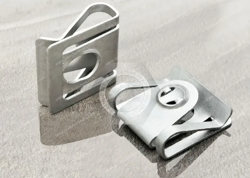
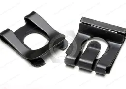
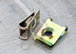
Clip-on nut panel thickness selection directly affects how a U-nut, J-nut, spring nut or other edge-mounted fastener installs, seats and remains positioned before screw tightening.
The correct selection process should therefore begin with the actual panel condition:
Finished Panel Thickness → Panel Edge Geometry → Clip Opening → Throat/Reach → Hole Setback → Thread Position → Installation Envelope
rather than:
Thread Size → Find Similar-Looking Clip
For OEM sourcing, JUXIN FASTENERS recommends specifying the complete panel interface instead of nominal sheet gauge alone.
A clip-on nut must physically pass over and fit the sheet-metal edge.
Depending on its geometry, part of the fastener may deflect during installation.
The amount of deflection is influenced by:
panel thickness;
clip opening;
spring-leg geometry;
material condition;
local bends;
panel coating;
edge configuration;
installation path.
If the production panel differs substantially from the condition for which the clip was designed, the fastener may no longer install or function as intended.
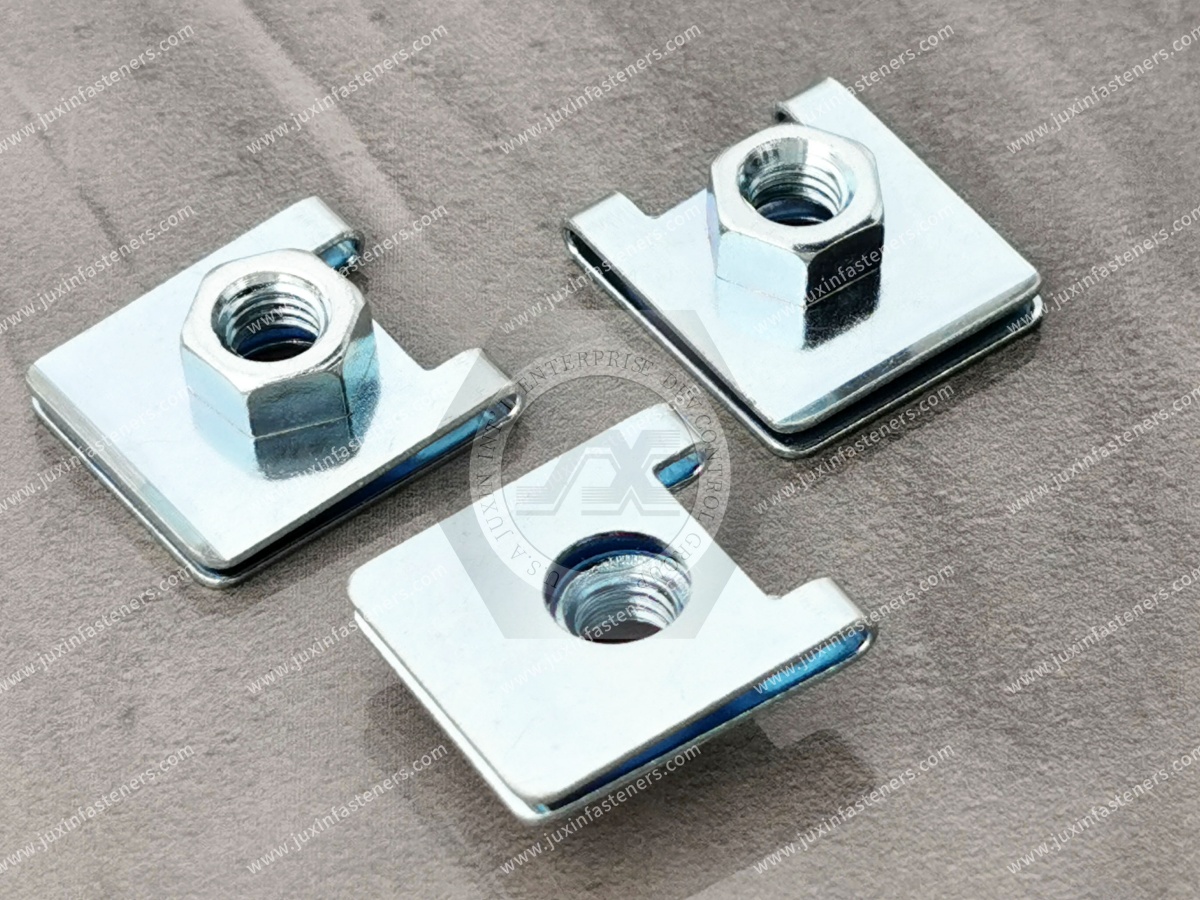
The term grip range is commonly used to describe the panel-thickness interval for which a particular clip-on fastener is intended.
However, grip range should not be treated as one universal value for all clip-on nuts.
Different fasteners can have different:
clip openings;
spring-leg geometries;
strip thicknesses;
material conditions;
throat dimensions;
edge configurations.
Therefore:
Every product requires its own confirmed panel-thickness range.
JUXIN FASTENERS should not publish one generic range and apply it to all U-nuts, J-nuts and spring fasteners.
Generic catalogs sometimes show example ranges for particular fasteners.
Those values should not be copied into an engineering guide as if they apply universally.
A clip-on nut designed for a thin panel may behave very differently from another product intended for a thicker panel.
The correct range must come from:
confirmed product data;
customer drawing;
existing sample;
engineering evaluation;
prototype fit validation.
This avoids turning an illustrative number into an unintended product guarantee.
A drawing may specify a nominal panel thickness such as:
1.0 mm
or:
0.040 in
But the actual production panel encountered by the fastener may not be exactly that dimension.
Variation can come from:
sheet material tolerance;
coating;
paint;
powder coating;
plating;
adhesive layers;
overlapping panels;
folded sheet;
local forming.
Therefore, clip-on nut selection should consider the actual production condition rather than the nominal sheet number alone.
A more useful engineering concept is the Finished Panel Thickness Window.
Instead of asking:
What is the nominal sheet thickness?
ask:
What is the minimum and maximum finished thickness the clip will actually encounter at the installation location?
Conceptually:
Finished Panel Thickness Window = Base Sheet Thickness Variation + Applied Surface Layers + Additional Sheet Layers Where Present
This is not intended as a universal mathematical formula for every sheet-metal assembly.
It is a design framework for identifying the real interface that the clip must accommodate.
The minimum condition helps determine whether the selected clip can interact with the thinnest expected production panel as intended.
The maximum condition helps determine whether installation requires excessive opening or interference.
Therefore, an RFQ containing:
Panel thickness: 1.0 mm
is less informative than:
Base material + nominal thickness + tolerance + finished coating condition
where those variables are known.
Many clip-on nut designs rely on controlled elastic deflection during installation.
As the clip moves over the panel edge, part of the fastener can deflect.
Within an appropriate component operating range, the geometry can recover sufficiently to provide the intended installed condition.
However, elastic behavior depends on the complete component:
Material Condition + Clip Geometry + Deflection + Panel Thickness
It cannot be predicted from material name alone.
If a spring component is deflected beyond the range appropriate to its material condition and geometry, some permanent deformation may occur.
This is commonly called permanent set.
For a clip-on nut, excessive installation deflection can potentially alter:
clip opening;
panel contact;
fastener position;
thread alignment;
installation/removal behavior.
But it is not correct to say that every panel slightly above a catalog limit will automatically cross the material yield point.
The actual response depends on the specific fastener.
If the actual panel condition is too thick for the selected clip geometry, possible symptoms can include:
high installation force;
difficult clip entry;
incomplete seating;
excessive clip opening;
permanent deformation;
coating damage;
thread-position shift;
interference with folded geometry.
The exact failure mode depends on the component.
A thicker panel does not always produce the same result.
A panel thinner than the intended fit condition can also create problems.
Depending on clip design, possible symptoms can include:
reduced pre-assembly retention;
clip movement during handling;
positional instability;
altered thread-to-hole alignment;
inconsistent assembly behavior.
However, it should not be stated universally that every undersized panel will make the clip rattle, slide or fall off.
That behavior must be evaluated for the specific fastener.
This distinction is essential.
Clip retention concerns how the fastener remains positioned on the panel before and during screw installation.
Joint strength concerns the completed screw-fastener-panel assembly after tightening.
Final joint performance can depend on:
screw specification;
thread engagement;
panel material;
panel thickness;
fastener geometry;
tightening process;
bearing area;
clamp load;
tensile loading;
shear loading;
vibration;
corrosion.
Correct panel fit is important, but it does not by itself establish joint strength.
A spring clip may apply local contact to the panel before the screw is installed.
That pre-assembly interaction should not be confused with the clamp load created by the tightened screw.
The two functions occur at different stages:
Before Screw Installation → Clip Positioning / Retention
After Tightening → Completed Joint Clamping
This distinction helps engineers avoid specifying a spring clip as though its edge grip were the primary structural clamp for the final joint.
Gemini's original draft suggested that correct gauge matching ensures perfect hole-center alignment.
That is too broad.
Hole alignment depends on several geometric variables:
hole location;
hole setback;
throat depth;
clip geometry;
manufacturing tolerance;
installation position.
Panel thickness can influence how the clip seats, but it does not independently determine the hole-center position.
For an edge-mounted clip-on nut, the distance from the panel edge to the intended screw axis is critical.
A useful geometric chain is:
Panel Edge → Clip Entry → Throat/Reach → Thread Center → Panel Hole
If the clip reach does not match the panel-hole position, the fastener may have the correct thread and correct panel thickness but still fail to align.
Therefore:
Correct Grip Range ≠ Correct Hole Setback
Both must be specified.
Panel thickness controls how the clip fits vertically around the sheet.
Throat depth or reach controls how far the fastening feature extends inward from the edge.
These dimensions solve different problems.
An alternate clip-on nut should therefore be evaluated in at least two directions:
Across the Panel Thickness
and:
From the Panel Edge to the Screw Axis
This is especially important in supplier replacement projects.
Sheet-metal panels may receive:
paint;
powder coating;
zinc-based coatings;
other protective finishes.
These surface layers can change the effective condition at the clip interface.
For a fastener already close to the upper end of its intended fit condition, coating buildup may become relevant.
Therefore, engineering should consider:
Bare Panel Condition
versus:
Finished Production Panel Condition
Not every coating is uniform at every location.
Edges, bends and flat surfaces may have different coating behavior depending on the process.
For this reason, the finished panel should be evaluated according to the actual manufacturing condition rather than using an assumed universal coating addition.
For tight-fit applications, production samples can provide valuable confirmation.
The panel is not the only coated component.
Carbon steel clip-on nuts may also receive a surface treatment.
Coating buildup on the clip can influence:
clip opening;
contact surfaces;
thread fit;
narrow clearances.
Therefore, dimensional validation should consider:
Finished Clip + Finished Panel
not:
Bare Clip + Bare Sheet
Powder coating can create a different panel interface from bare sheet metal.
Depending on the coating system and geometry, engineers may need to consider:
finished thickness;
coating compression;
coating damage during installation;
edge buildup;
local scratching.
The goal is not simply to make the clip fit.
The assembly process should also avoid unintended damage to the required panel finish.
Galvanized sheet can also change the finished surface condition.
For clip selection, engineers should identify whether the specified panel thickness refers to:
base steel thickness;
coated sheet thickness;
another drawing-defined dimension.
The drawing and purchasing specification should make this clear.
Some clip-on nuts are installed over more than one sheet layer.
Examples can include:
overlapping panels;
bracket-to-panel edges;
folded returns;
reinforced local sections.
In these cases, the clip does not see the thickness of one sheet.
It sees the effective stack at the installation point.
Therefore:
Nominal Single-Sheet Thickness ≠ Installed Stack Thickness
This can be a major source of sourcing errors.
A folded flange or return can create:
multiple sheet layers;
bend-radius interference;
restricted installation access;
different effective thickness;
altered hole position.
A clip selected for a flat sheet edge should not automatically be used on a folded flange.
For detailed guidance, see Clip-On Nuts for Flanged Edges: Fastening Folded Sheet-Metal Panels at /solutions/clip-on-nuts-for-flanged-edges.
This is another useful engineering distinction.
A hemmed edge introduces geometry that cannot always be represented by adding two nominal sheet thicknesses.
The bend, contact condition and local shape can affect how the clip enters and seats.
For hemmed or complex folded edges, provide the cross-sectional drawing rather than only an aggregate thickness number.
For simple flat panels, thickness plus hole setback may be enough to begin selection.
For complex edges, a cross-sectional drawing can show:
sheet layers;
bends;
radii;
flange direction;
coating;
nearby interference;
installation path.
This often provides more useful information than a single “panel gauge” field in a purchasing form.
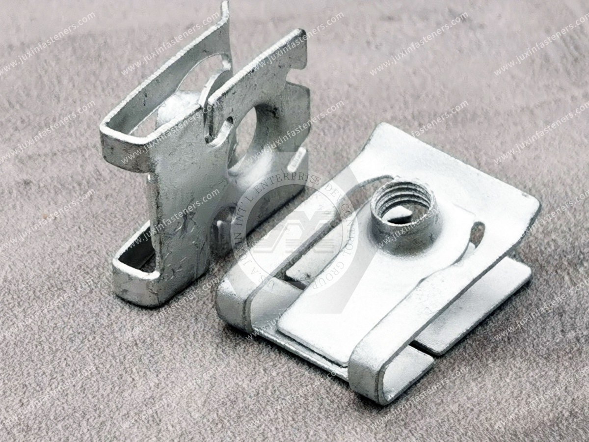
Sheet-metal gauge numbers should be used carefully in international sourcing.
A gauge number does not represent one universal thickness across every material and convention.
For example, steel, stainless steel and aluminum gauge systems can differ.
Therefore, a global OEM RFQ should preferably include:
Material + Actual Thickness + Tolerance
rather than gauge number alone.
For metric designs, specify actual panel thickness in millimeters.
Where relevant, include:
nominal thickness;
minimum;
maximum;
finished condition.
This avoids ambiguity associated with converting a local sheet-gauge convention.
For more metric specification guidance, see Metric Clip-On Nuts: Thread Size, Panel Thickness & OEM Sourcing Guide at /solutions/metric-clip-nuts-selection.
For inch-series designs, actual panel thickness in decimal inches can provide a clearer purchasing specification than gauge alone.
Where appropriate, an equivalent millimeter dimension can be added for communication, but the controlling drawing unit should remain clear.
For more information, see Inch Clip-On Nuts: UNC/UNF Threads, Panel Thickness & OEM Sourcing at /solutions/inch-clip-nuts-selection.
Clip-on nuts may use:
carbon steel;
spring steel;
stainless steel;
other project-specific materials.
Material condition influences component behavior.
However, material alone does not define panel range.
A 65Mn clip and a stainless steel clip with different geometries cannot be compared from material name alone.
Grip capability remains a finished-part characteristic.
Where 65Mn is explicitly specified, panel-fit selection should still be based on the actual finished component.
The material designation does not guarantee:
a particular grip range;
a particular retention force;
unlimited elastic recovery;
repeated installation capability.
For additional material guidance, see 65Mn Spring Steel Clip-On Nuts: Material Selection, Elastic Recovery & Panel Fit at /solutions/65mn-spring-steel-clip-nuts.
Carbon and spring steel clip-on nuts can be used in many sheet-metal assemblies.
Material, heat-treatment condition where applicable, coating and geometry all contribute to the finished component.
For broader material and surface-treatment guidance, see Carbon Steel Clip-On Nuts: Material Grades, Coatings & OEM Selection at /solutions/carbon-steel-clip-on-nuts-material-coating-guide.
Panel thickness alone does not determine whether a U-nut or J-nut is correct.
Geometry selection should also consider:
hole setback;
throat depth;
installation direction;
surrounding clearance;
edge geometry.
For a detailed comparison, see U-Nuts vs J-Nuts: Geometric Selection for Edge-Mounted Sheet Metal at /solutions/u-nuts-vs-j-nuts-geometry.
Sometimes a particular fastener is designed to accommodate a defined thickness interval.
But the existence and width of that range are product-specific.
Engineering teams should not assume that one “universal” clip nut will perform identically across every panel used in an enclosure family.
If several panel thicknesses are involved, compare:
minimum panel condition;
maximum panel condition;
required clip position;
installation force;
retention requirement;
hole alignment.
Then determine whether one validated part can cover the complete production window.
Standardizing one clip across multiple panel variants can reduce:
BOM complexity;
inventory;
line-side part variation;
procurement complexity.
But standardization should follow engineering validation.
A lower part count is valuable only if the selected fastener works correctly across the complete required panel range.
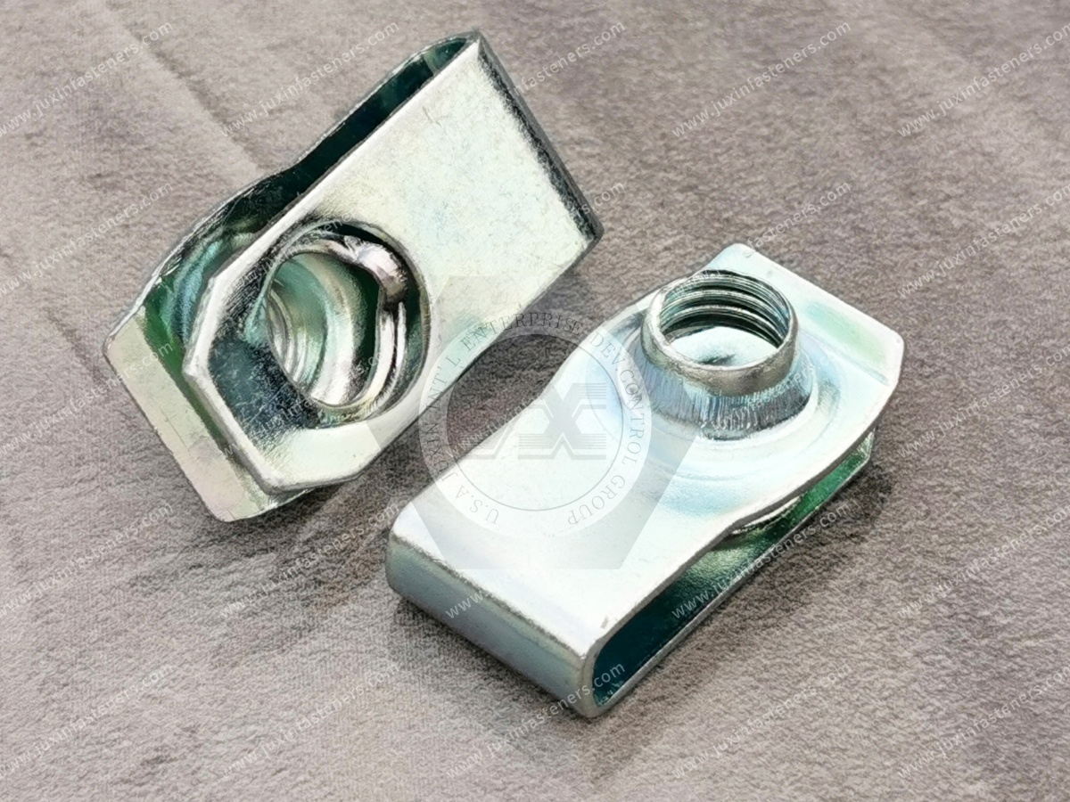
If two panels have substantially different:
thicknesses;
edge geometries;
hole setbacks;
installation envelopes;
forcing one clip-on nut to serve both may create unnecessary compromise.
In that case, separate optimized part numbers may provide better assembly control.
This is a design and procurement decision, not simply a catalog-selection decision.
Automotive sheet-metal assemblies can contain different material thicknesses and coatings across:
brackets;
service covers;
interior structures;
auxiliary equipment panels;
selected shields.
For suitable clip-on nut applications, the production panel condition should be confirmed.
Correct panel fit does not automatically establish:
vibration resistance;
fatigue performance;
crash capability;
structural suitability.
Those remain separate validation requirements.

EV platforms contain sheet-metal housings, brackets and covers outside primary structural and sealing joints.
Potential suitable applications can include:
electronics covers;
control housings;
service panels;
auxiliary brackets.
Panel thickness selection remains important, particularly where lightweight sheet structures and coatings are used.
A clip-on nut should not automatically be described as an IP-rated, battery-sealing, grounding or structural battery fastener.
Electrical cabinets can contain:
frames;
removable covers;
control panels;
internal brackets;
folded flanges.
Different cabinet sections may use different sheet thicknesses.
A clip standardized for one section should not automatically be assumed suitable for every panel in the cabinet.
HVAC housings can combine:
flat panels;
folded flanges;
coated sheet;
service covers;
control enclosures.
Panel-fit evaluation should consider the finished production geometry.
The clip itself should not be treated as an air seal, waterproofing component or vibration isolator.
Industrial machinery may use clip-on nuts on:
access panels;
equipment covers;
control housings;
brackets;
non-structural guards.
Where guards perform safety-related functions, the complete joint and applicable safety requirements should be evaluated separately.
Panel-fit compatibility alone does not establish safety-critical suitability.

Automation equipment often has compact sheet-metal housings with limited installation space.
Here, engineers may need to coordinate:
panel thickness;
clip height;
throat depth;
screw protrusion;
nearby electronics;
cable routing.
A clip can fit the sheet thickness correctly and still be unsuitable because its overall envelope interferes with another component.
This leads to an important design principle.
A clip-on nut must usually fit in several dimensions simultaneously.
Can the clip fit the finished panel thickness?
Does the clip reach the correct hole center?
Does the fastener fit between nearby bends or features?
Is there sufficient space above and below the panel?
Does the threaded feature align with the mating screw?
Therefore:
Panel Thickness Compatibility ≠ Complete Fastener Compatibility
| Variable | Engineering Question |
|---|---|
| Panel material | What sheet material is used? |
| Nominal thickness | What does the drawing specify? |
| Thickness tolerance | What are the production minimum and maximum? |
| Surface finish | Paint, powder coating, plating or other coating? |
| Number of layers | One sheet, overlap, flange or folded stack? |
| Finished thickness window | What will the clip actually encounter? |
| Edge geometry | Flat, flange, return, hem or other profile? |
| Clip opening | Is the product intended for this panel condition? |
| Hole setback | Where is the screw axis relative to the edge? |
| Throat depth | Can the clip reach that location? |
| Material | What clip material is specified? |
| Clip coating | Does coating affect final fit? |
| Installation direction | How is the fastener introduced onto the panel? |
| Envelope | Is there sufficient surrounding clearance? |
This matrix is more useful than choosing a clip from thread size and gauge alone.
The best time to select a clip-on nut is before the sheet-metal drawing is completely frozen.
Early coordination allows the engineer to align:
sheet thickness;
hole location;
edge geometry;
clip reach;
screw interface;
installation access.
If fastener selection is delayed until after tooling or punching patterns are fixed, the available replacement options may become more limited.
The problem is different when procurement needs a second source for an existing part.
In that situation, the panel is already designed.
The alternative supplier must match the existing interface.
Supplier qualification should compare:
thread;
panel range;
clip opening;
throat depth;
hole setback;
overall geometry;
material;
coating.
A visually similar part is not enough.
There is no reliable rule such as:
M6 = this panel range
or:
1/4-20 = this panel thickness.
Thread size and panel thickness solve different engineering requirements.
Two M6 clip nuts can be designed for different panel conditions.
Two 1/4-20 clip nuts can also have different openings and reaches.
Likewise:
65Mn ≠ specific panel range
304 stainless ≠ specific panel range
carbon steel ≠ specific panel range
Grip range belongs to the finished product design.
For a new OEM application, prototype evaluation should use a representative production panel whenever possible.
Evaluate:
installation;
seating;
position;
hole alignment;
screw starting;
surrounding clearance;
visible panel/coating damage.
Where the application has additional functional requirements, those should be evaluated separately.
Testing only one ideal nominal panel can miss problems that appear at production extremes.
Where appropriate, evaluation can include representative conditions near:
minimum finished thickness;
nominal finished thickness;
maximum finished thickness.
The exact validation plan should follow the application's risk and customer requirements.
For production control, inspection requirements can focus on the dimensions that actually affect assembly.
Depending on the part, these can include:
clip opening;
throat/reach;
thread position;
overall geometry;
material thickness;
relevant formed dimensions.
The inspection plan should follow the approved drawing rather than a generic website checklist.
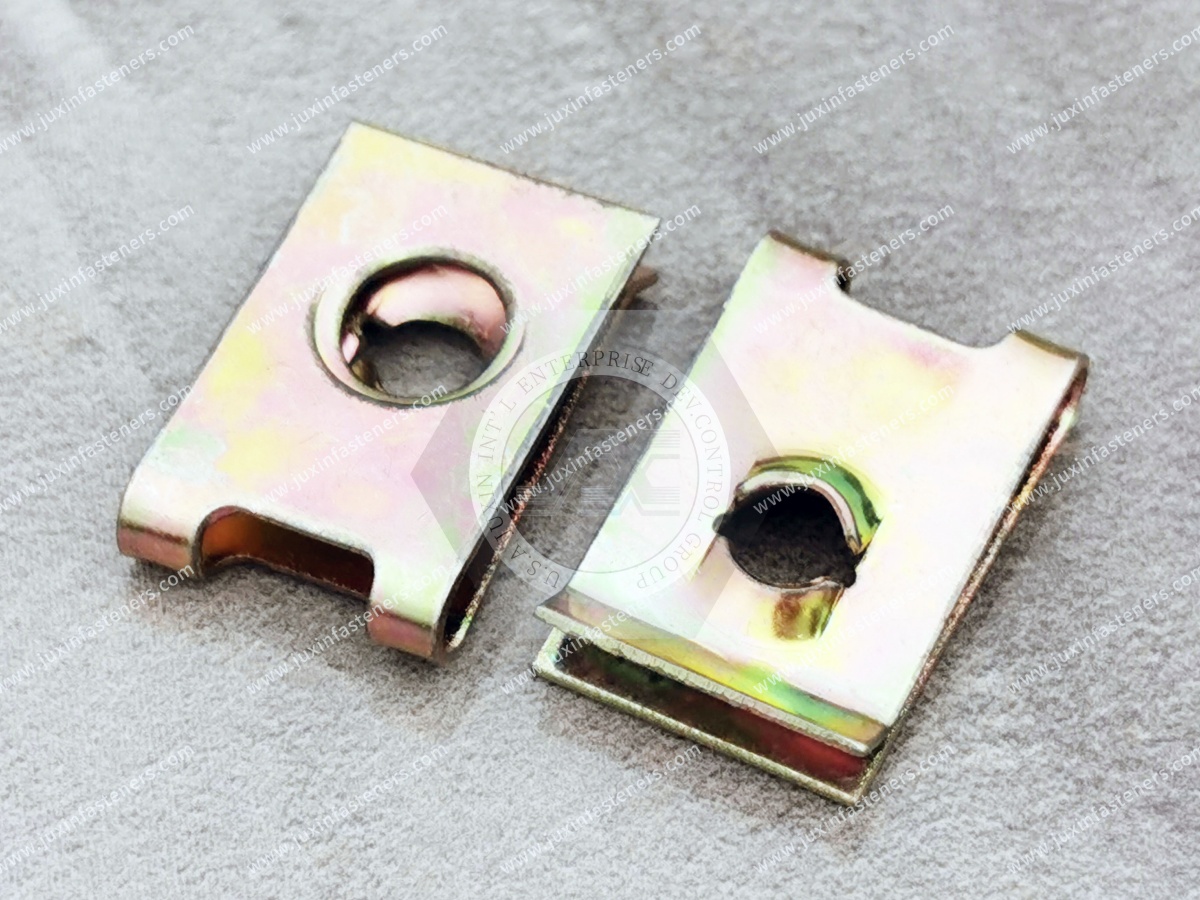
Metric threads may reference ISO standards.
Unified inch threads may reference ASME standards.
Materials and coatings may have their own applicable ASTM, SAE, EN or other specifications.
But this does not mean there is one international standard that defines the panel grip range for every proprietary U-nut, J-nut or spring clip.
In many OEM projects, the component drawing remains the primary dimensional control.
This distinction prevents standards from being cited outside their actual scope.
An engineer may search:
clip-on nut panel thickness;
U-nut grip range;
spring clip panel tolerance;
how to size a clip nut;
clip nut too tight on panel.
Procurement may search:
clip nut supplier for 1 mm sheet;
U-nut replacement supplier;
clip-on nut manufacturer;
custom spring nut supplier;
alternate clip nut source.
Both search journeys should ultimately converge on the same technical specification:
Actual Panel + Clip Geometry + Thread + Material + Finish
A robust selection process can follow:
Panel Material → Nominal Thickness → Thickness Tolerance → Coating → Finished Panel Window → Edge Geometry → Hole Setback → Clip Reach → Thread → Material → Finish → Prototype Fit → Joint Validation
This prevents thread size from dominating a problem that is fundamentally controlled by the sheet-metal interface.
When qualifying an alternative clip-on nut, compare:
customer part number;
drawing revision;
clip geometry;
thread specification;
panel thickness range;
clip opening;
throat depth;
hole setback;
overall dimensions;
material;
material condition where relevant;
surface treatment;
installation direction;
mating screw;
inspection requirements.
A supplier's stated “compatible panel gauge” should be verified against the actual production panel condition.
When submitting an RFQ to JUXIN FASTENERS at info@juxinfasteners.com, provide as much of the following information as available:
2D engineering drawing;
panel cross-section where relevant;
3D CAD model where useful;
existing physical sample;
reference photograph;
customer part number;
existing supplier/reference part number;
U-nut, J-nut or other clip geometry;
metric or inch thread system;
thread designation;
thread pitch or TPI;
mating screw;
panel material;
nominal base-sheet thickness;
minimum base-sheet thickness where relevant;
maximum base-sheet thickness where relevant;
finished panel minimum thickness where known;
finished panel maximum thickness where known;
paint or powder-coating condition;
plating or galvanized condition;
number of sheet layers;
flange, return or hem geometry;
bend radius where relevant;
hole diameter;
hole setback;
throat or reach dimension;
surrounding clearance;
installation direction;
clip material;
required material grade where applicable;
surface treatment;
trivalent chromium zinc requirement where applicable;
RoHS/REACH requirements where applicable;
corrosion requirements where applicable;
prototype/sample quantity;
production order quantity;
annual demand;
packaging requirements;
labeling requirements;
inspection requirements;
customer-specific specifications.
A generic engineering search may begin with:
“What panel thickness fits this clip-on nut?”
But a production-ready sourcing requirement should evolve into:
“This clip must fit this finished minimum-to-maximum panel condition, align with this hole setback, use this thread and mating screw, and meet this material and coating specification.”
The commercial conversion path is:
Panel Thickness Search → Finished Panel Window → Edge Geometry → Clip Opening → Hole Setback → Throat Depth →
Thread Interface → Material → Finish → Prototype Evaluation → Joint Validation → Approved Drawing → Supplier RFQ → Repeat Supply
That turns a simple thickness question into an OEM-controlled fastening specification.
For drawing-based clip-on nuts, U-nuts, J-nuts, spring nuts, metric clip nuts, inch clip nuts and custom edge-mounted sheet-metal fasteners, contact JUXIN FASTENERS at info@juxinfasteners.com.
Providing the actual panel material, finished thickness range, edge cross-section, hole setback,
thread requirement and annual demand allows JUXIN FASTENERS to evaluate the fastening requirement much more accurately than specifying sheet gauge alone.
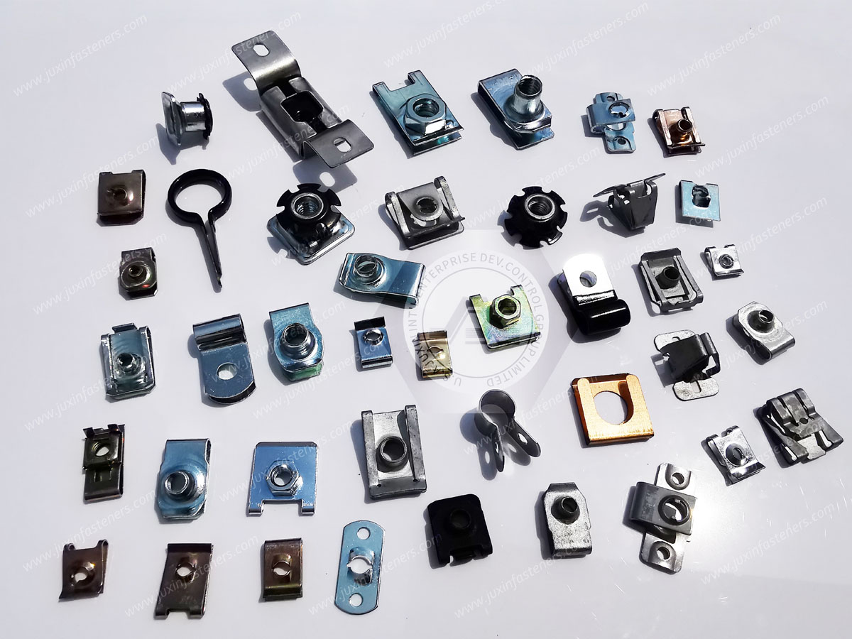
Product Packaging
Packaging Standard
At Juxin Fasteners, we apply standardized export packaging to ensure product protection, traceability, and compliance with international logistics requirements.
1. Standard Export Packaging
Unless otherwise specified, all products will be packed according to our factory standard export packaging, which includes:
Moisture-resistant inner protection
Poly bag or small box packing as required
Reinforced export cartons
Clear labeling with part number, specification, batch number, and quantity
Palletizing for sea or air shipment when necessary
Our standard packaging is designed to ensure safe transportation, efficient warehousing, and long-distance international shipping.
2. Customized Packaging Options
We also provide customized packaging solutions according to customer requirements, including but not limited to:
Private labeling
Customized barcodes
Specific carton dimensions
Retail packaging
Special pallet configuration
Customer-specific marking and identification
So that you know, customized packaging may involve additional costs and extended lead time depending on the complexity of the requirements.
3. Compliance & Quality Assurance
All packaging processes are controlled under our ISO 9001 quality management system to ensure consistency, traceability, and product integrity throughout the supply chain.
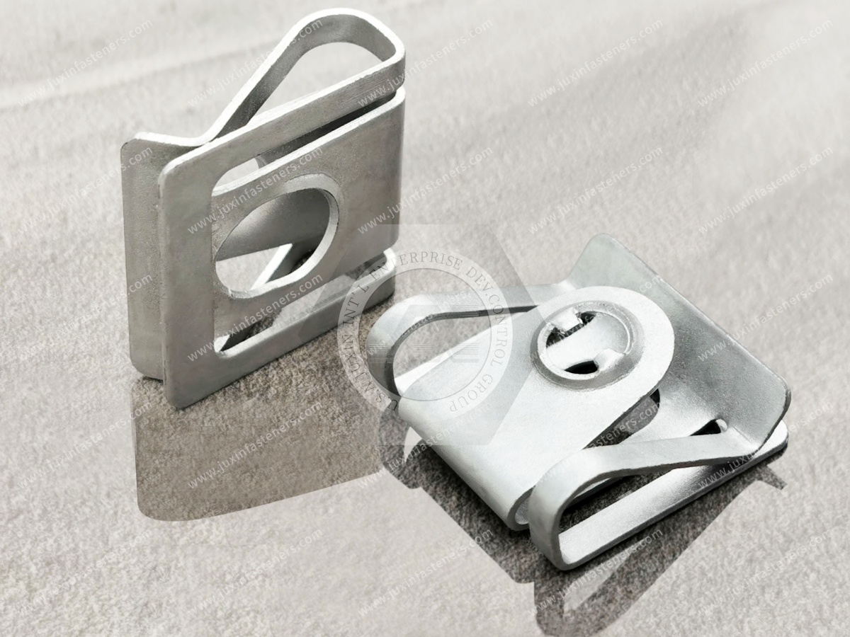
Product Pictures
Contact Us
Tel.:
+86 020 8621 0320
+86 020 3121 6067
E-mail:
Technical Support:
Navigation
SEND INQUIREY