Call Us
+86 136 6007 9809
Call Us
+86 136 6007 9809

When designing sheet-metal enclosures, industrial machinery chassis, automotive assemblies, electrical cabinets,
HVAC equipment or equipment housings, establishing reliable threaded attachment points is a fundamental engineering task.
The difficult question is not whether the assembly needs a thread.
Product Specification
When designing sheet-metal enclosures, industrial machinery chassis, automotive assemblies, electrical cabinets,
HVAC equipment or equipment housings, establishing reliable threaded attachment points is a fundamental engineering task.
The difficult question is not whether the assembly needs a thread.
It is:
What is the most appropriate way to create that thread in the sheet-metal structure?
Four common fastening architectures are:
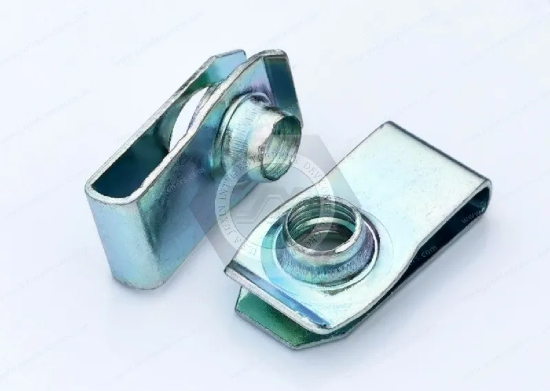
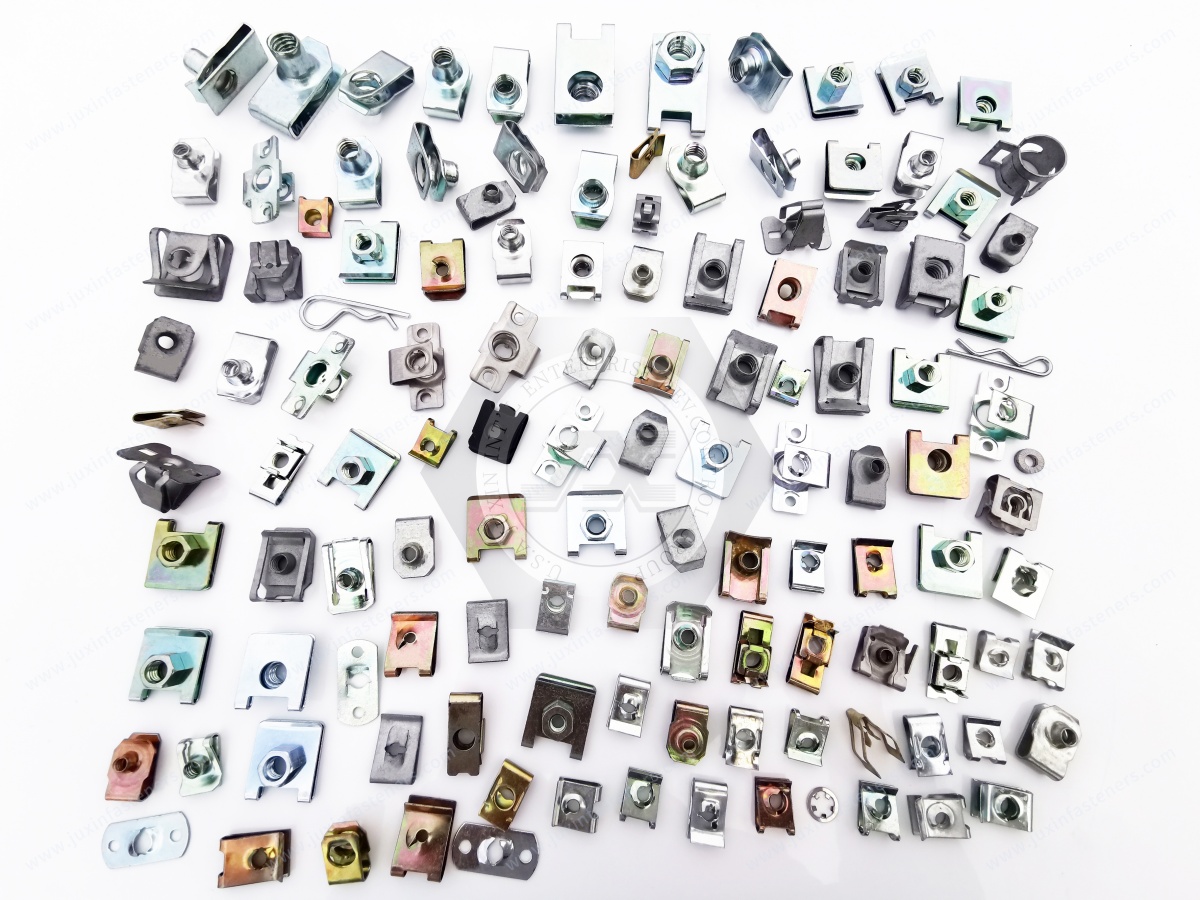
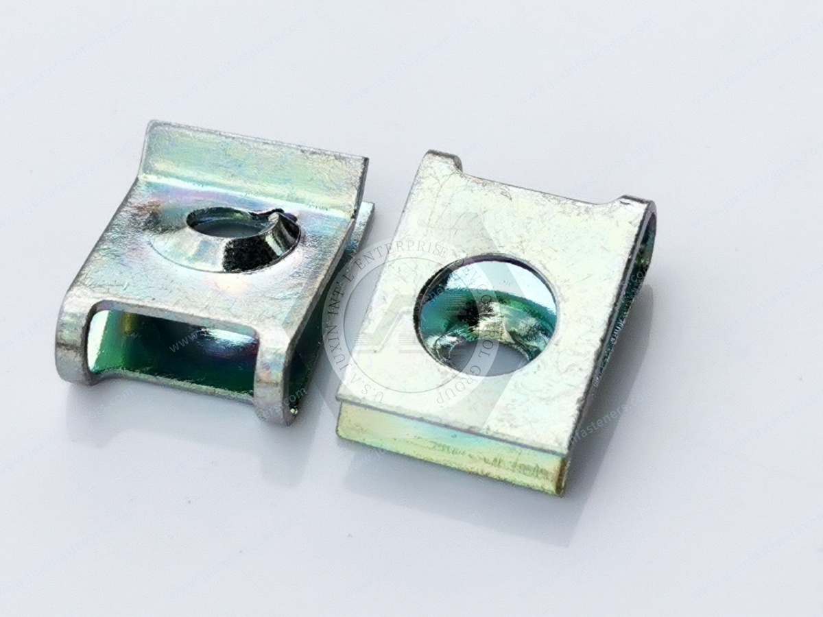
Clip-on nuts, including U-nuts, J-nuts and other edge-mounted spring nuts;
Weld nuts, including projection weld nuts and other welded threaded components;
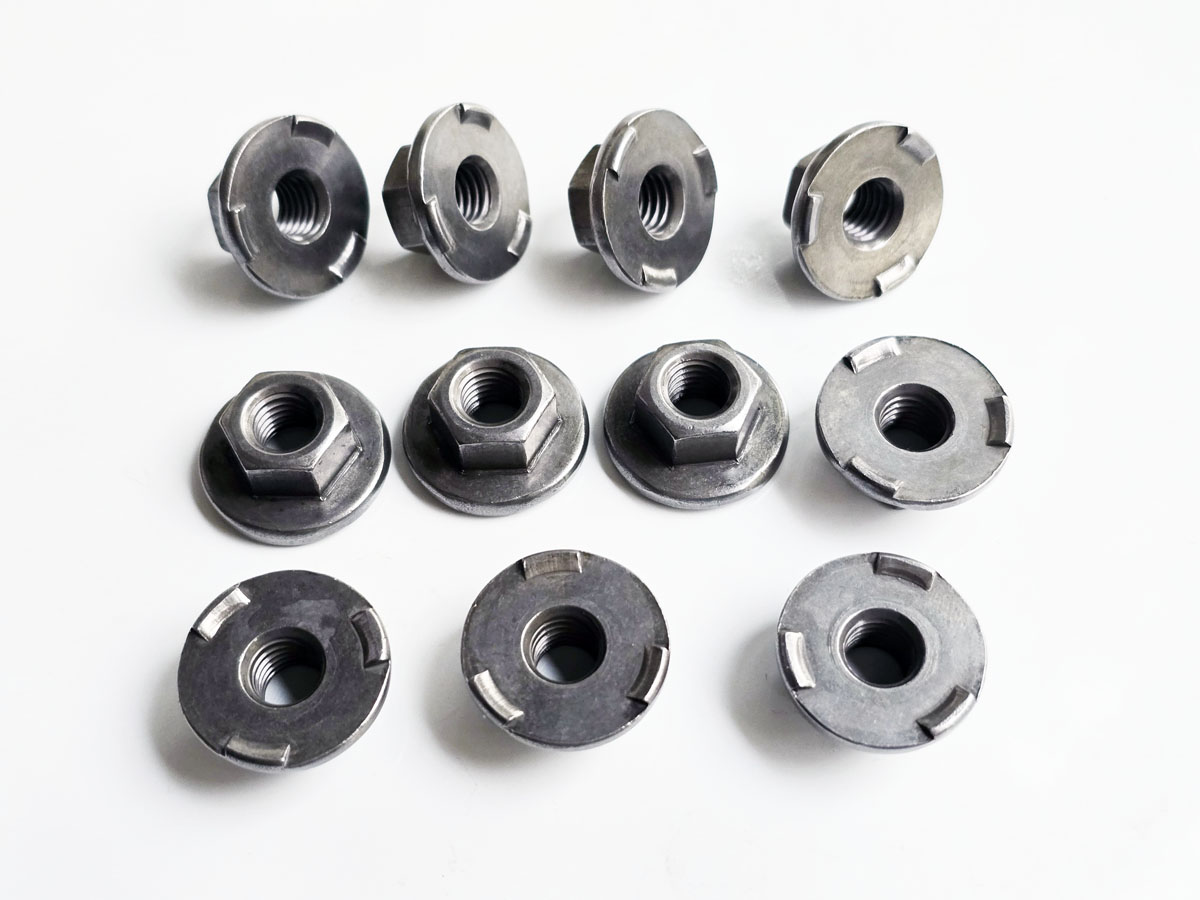
Self-clinching nuts, mechanically installed into prepared sheet-metal holes;
Blind rivet nuts, installed from one accessible side of a panel.
Each can provide a reusable internal thread for a mating screw or bolt.
But they are not interchangeable fastening technologies.
They differ in:
fastener location;
panel-edge access;
backside access;
parent material;
panel thickness;
hole preparation;
installation equipment;
production sequence;
surface finishing;
tolerance accommodation;
mechanical load path;
serviceability;
repair strategy;
automation potential;
total production cost.
For design engineers and strategic sourcing teams, effective sheet-metal fastener selection therefore requires matching the fastening architecture to
the complete manufacturing and service environment rather than selecting only by thread size.
An engineer may begin with:
“We need an M6 threaded attachment point.”
But M6 alone does not determine whether the application should use a clip-on nut, weld nut, self-clinching nut or rivet nut.
The first question should be:
Where must the thread be located relative to the sheet-metal geometry?
This immediately separates several fastening architectures.
An edge-mounted clip-on nut may be practical.
A conventional edge clip may not reach the required location.
Depending on the assembly, engineers may instead evaluate:
weld nuts;
self-clinching nuts;
blind rivet nuts;
another installed threaded insert.
This creates the first important selection rule:
Thread Location → Fastener Architecture
Although all four technologies can create a usable female thread in a sheet-metal assembly, each does so through a different mechanical principle.
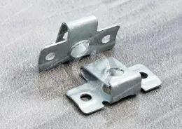
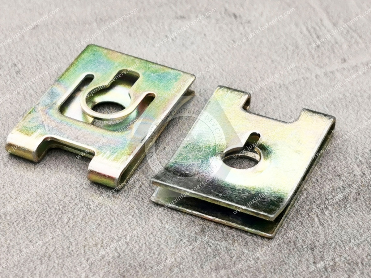
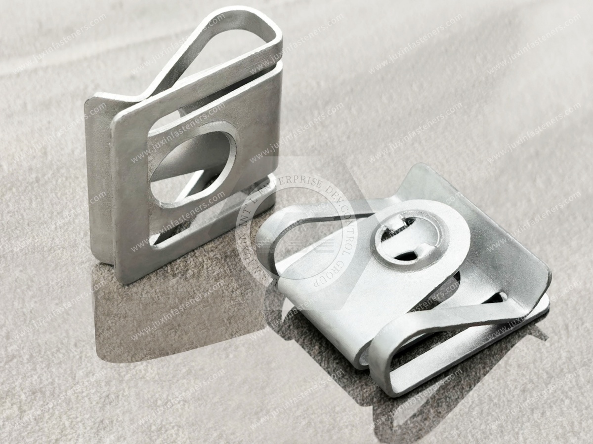
Clip-on nuts are mechanically attached to a panel edge or flange.
Common configurations include:
U-nuts;
J-nuts;
clip-on enclosed hex nuts;
spring nuts for machine screws;
spring clips for tapping screws.
Depending on the design, the threaded feature may be:
formed into the spring component;
integrated into a nut element;
configured for a tapping screw;
incorporated into another clip architecture.
Their major distinguishing characteristic is that they generally do not require welding or permanent press installation into the panel.
Clip-on nuts can provide several manufacturing advantages where the geometry is suitable:
edge installation;
no welding;
no hydraulic or mechanical clinching press at the assembly point;
potential post-finish installation;
relatively easy replacement;
efficient manual or automated assembly depending on design;
tolerance accommodation in suitable clip configurations.
However, they require compatible panel-edge geometry.
Therefore:
Clip-On Nut Advantage = Edge-Based Mechanical Attachment
not:
Clip-On Nut = Universal Replacement for Every Sheet-Metal Nut
U-nuts and J-nuts are both edge-mounted spring fasteners, but their geometry and application can differ.
For detailed comparison, see U-Nuts vs J-Nuts Geometry.
For broader product selection, see Clip-On Nuts, U-Nuts & J-Nuts Selection Guide.
Weld nuts create a threaded attachment by joining the nut to the sheet-metal structure through an appropriate welding process.
Common architectures include:
square projection weld nuts;
hex weld nuts;
flange weld nuts;
other drawing-specific welded nuts.
Projection welding is widely used for suitable weld-nut and sheet combinations.
Other welded threaded components may use different welding processes depending on product design and application.
The thread becomes physically joined to the sheet-metal component before final screw assembly.
This can make weld nuts attractive where the manufacturing route already supports:
welding;
fixture control;
process validation;
suitable parent materials;
permanent threaded attachment.
However, the welding operation becomes part of the fastener system.
The engineer must therefore consider:
projection geometry where applicable;
sheet material;
sheet thickness;
welding parameters;
electrode access;
fixture design;
weld quality;
distortion;
spatter;
thread protection;
downstream finishing.
A weld nut can provide a robust threaded attachment when the weld and joint are correctly designed and controlled.
But it is technically incorrect to assume:
Weld Nut = Automatically Highest Strength
The actual joint performance depends on:
nut geometry;
weld quality;
sheet material;
sheet thickness;
weld process;
loading direction;
screw or bolt;
complete structural design.
Fastener technology should therefore be selected from validated joint requirements rather than a generic strength hierarchy.
Self-clinching nuts are installed into properly prepared holes in suitable sheet material using controlled pressing force.
During correct installation, parent material is displaced into the fastener's retention features.
This creates mechanical resistance to:
push-out;
rotation.
The exact installation mechanism depends on the fastener design.
Self-clinching fasteners are attractive when engineers need a threaded attachment at a location that is not limited to a panel edge and where the sheet material, thickness and manufacturing process are suitable.
Important design factors include:
panel material;
panel hardness;
panel thickness;
hole diameter;
hole quality;
edge distance;
installation force;
installation tooling;
fastener orientation.
A self-clinching nut is installed by controlled pressing force, not by tightening it into the panel.
Correct installation depends on material displacement and fastener geometry.
Therefore:
More Installation Force ≠ Automatically Better Installation
The fastener supplier's requirements and validated installation process should control the operation.
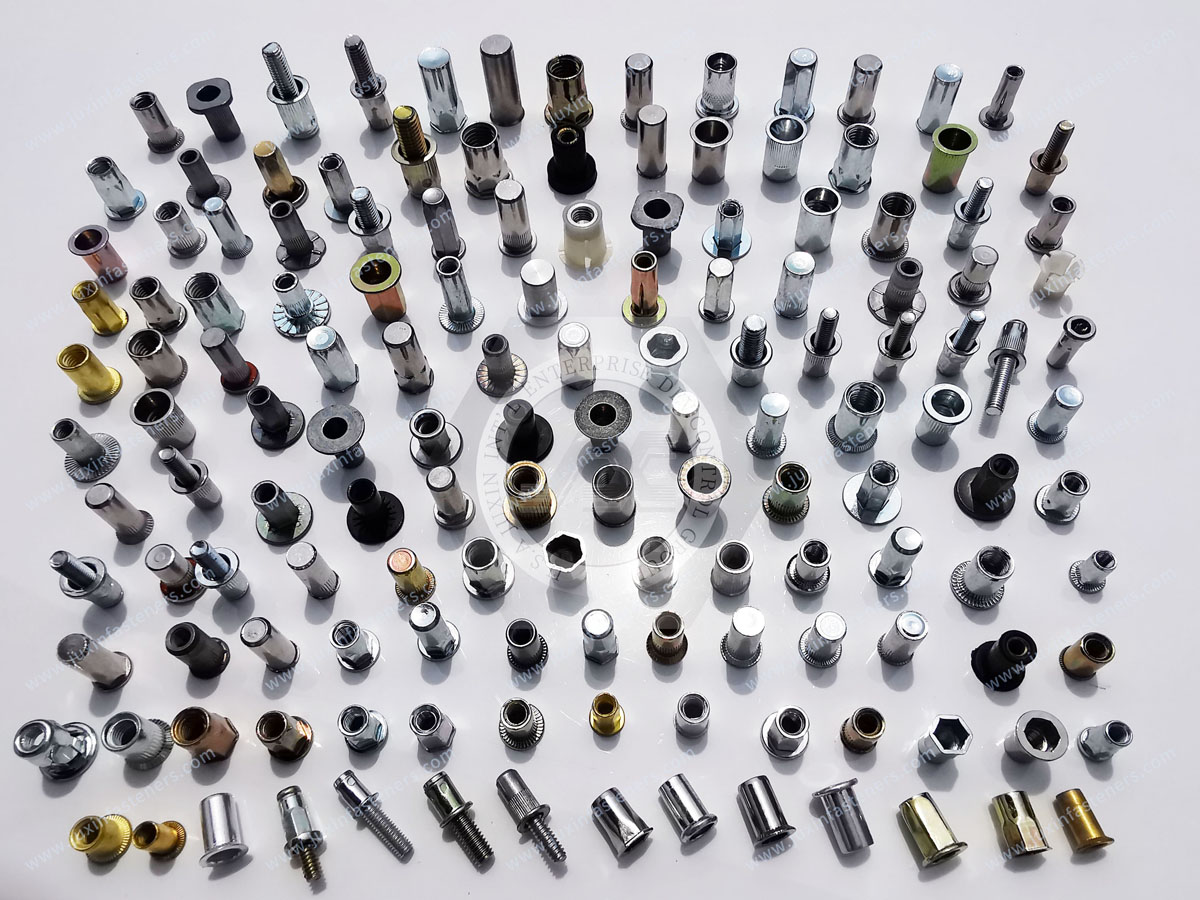
Blind rivet nuts, also called rivet nuts or threaded inserts for blind installation, are tubular threaded fasteners installed through a prepared hole from one accessible side of the workpiece.
During installation, the setting process deforms the designated portion of the rivet nut so that it mechanically captures the panel.
This makes blind rivet nuts particularly useful when the backside of the structure cannot be accessed during installation.
Their key architectural advantage is:
One-Side Installation
This is useful for:
closed sections;
tubes;
hollow profiles;
assembled enclosures;
inaccessible backside structures;
repair and retrofit applications.
Blind rivet nuts are also available in multiple body geometries, including configurations designed to address different:
panel grip ranges;
anti-rotation requirements;
flange requirements;
material systems;
installation conditions.
For a detailed engineering overview, see Blind Rivet Nuts: Comprehensive Engineering Guide.
Before comparing price or strength, compare how each fastener enters the assembly.
| Fastener Type | Primary Installation Principle | Typical Location | Backside Access During Installation | Welding Required | Dedicated Installation Process |
|---|---|---|---|---|---|
| Clip-On Nut | Spring clip over edge/flange | Edge / flange | Often not required | No | Usually simple clip installation |
| Weld Nut | Welded to sheet | Edge or mid-panel depending design | Process-dependent | Yes | Welding equipment and control |
| Self-Clinching Nut | Pressed into prepared hole | Mid-panel or suitable flange | Tooling access required for installation setup | No | Pressing operation |
| Blind Rivet Nut | Mechanically set through hole | Mid-panel / tube / enclosure | No backside access required | No | Rivet-nut setting tool |
This table immediately shows why these technologies should not be treated as direct substitutes.
If yes, clip-on nuts may offer a simple solution.
If no, evaluate a mid-panel technology such as:
weld nut;
self-clinching nut;
blind rivet nut.
This decision alone can eliminate an entire fastener family.
Backside accessibility strongly affects manufacturing options.
The design may support:
self-clinching installation;
welding processes;
other two-side tooling architectures.
A blind rivet nut becomes particularly attractive because installation can be performed from the accessible side.
An edge clip may also work if the required location is reachable from the panel edge.
These terms should not be confused.
A clip-on nut can often be installed without reaching behind the panel, but it generally requires access to an appropriate panel edge.
A blind rivet nut can create a threaded attachment in a prepared hole even when the backside is inaccessible.
Therefore:
Edge Access ≠ Blind-Hole Access
Some manufacturing environments already have controlled resistance-welding processes.
In those cases, weld nuts may integrate efficiently into the production route.
Other applications may avoid welding because of:
material combination;
distortion concerns;
downstream finishing;
low-volume manufacturing;
equipment availability;
repair requirements;
process simplification.
When welding is undesirable, engineers can evaluate:
clip-on nuts;
self-clinching nuts;
blind rivet nuts.
Self-clinching technology depends on the relationship between the fastener and parent sheet.
Engineers must verify that the sheet:
has appropriate thickness;
has suitable mechanical properties;
has a correctly prepared hole;
provides sufficient material around the installation location.
A self-clinching nut should not be selected solely because the thread and hole diameter appear compatible.
The manufacturing sequence can strongly influence fastener selection.
A typical route may include:
Blanking → Forming → Fastener Installation → Welding → Cleaning → Painting / Powder Coating → Final Assembly
or:
Blanking → Forming → Painting / Powder Coating → Clip Installation → Final Assembly
The correct sequence depends on the product and process.
One major advantage of clip-on nuts is that many designs can be installed after:
painting;
powder coating;
other finishing operations.
This can reduce the need to expose fastener threads to coating processes.
However, clip installation itself may contact the finished panel.
Engineers should consider:
coating thickness;
scratching risk;
clip grip range;
appearance requirements;
corrosion implications.
Weld nuts are generally installed as part of the fabrication process before finishing when subsequent coatings are required.
This creates additional process considerations.
Depending on the finishing system, thread protection or post-process thread inspection may be required.
The exact solution depends on:
coating type;
coating thickness;
thread requirement;
production process.
Do not assume every weld-nut thread must use the same masking method.
Self-clinching nuts may be installed at different stages depending on:
panel finish;
fastener material;
installation requirements;
cosmetic requirements;
manufacturing route.
Pressing a self-clinching fastener into a finished panel can affect the coating around the installation zone.
The process must therefore be validated rather than treated as universally pre-paint or post-paint.
Blind rivet nuts can often be useful for post-finish assembly because they are mechanically installed without welding.
However, installation can still affect:
coating around the hole;
bearing surface;
local panel deformation.
Post-finish compatibility should be validated for the actual panel and fastener.
| Question | Clip-On Nut | Weld Nut | Self-Clinching Nut | Blind Rivet Nut |
|---|---|---|---|---|
| Can avoid welding before paint? | Yes | No | Yes | Yes |
| Can potentially be installed after finishing? | Yes | Process-dependent | Process-dependent | Yes, where validated |
| Thread exposed during coating if pre-installed? | Avoidable with post-installation | Potentially | Potentially | Avoidable with post-installation |
| Can installation affect finished surface? | Yes | Not applicable if welded before finish | Yes | Yes |
This is a more useful manufacturing comparison than simply labeling one technology “better.”
Serviceability is one of the strongest differentiators between these systems.
Many clip-on nuts can be removed and replaced without permanently modifying the panel, provided the panel itself has not been damaged.
Replacement normally requires repair of the welded attachment and should follow an approved repair process.
Removal generally disturbs the installed interface and may affect the panel hole or surrounding material.
Removal generally requires destructive removal of the installed rivet nut and evaluation of the remaining hole.
This creates an important design question:
What happens if the thread is damaged after the product reaches the field?
Field-service cost is often overlooked during initial fastener selection.
For an access cover that may be removed repeatedly over many years, replacement strategy can matter significantly.
For a permanent internal structural attachment that is rarely serviced, the priorities may be different.
Therefore:
Production Installation Cost ≠ Total Lifecycle Cost
Some clip-on nut configurations can provide positional accommodation because the thread feature or clip architecture allows limited movement.
This can be useful where multiple sheet-metal parts must align during final assembly.
However:
Not Every Clip-On Nut Is a Floating Nut
Tolerance accommodation depends on the specific geometry.
Weld nuts, self-clinching nuts and rivet nuts also have their own positional tolerances based on:
hole location;
installation process;
fastener geometry;
fixture control.
Tolerance strategy should therefore be designed, not assumed.
Consider an enclosure with several screws installed through a removable cover.
If hole-position tolerance accumulates across a large panel, a completely rigid thread pattern can make assembly difficult.
Possible solutions include:
controlled hole tolerances;
larger clearance holes where appropriate;
floating fastening architectures;
appropriate clip geometry.
The correct solution depends on the complete assembly.
Do not select the fastening technology based only on statements such as:
weld nuts are strongest;
clip nuts are weakest;
rivet nuts are medium strength.
These generic rankings can be misleading.
The relevant question is:
What load must this particular joint carry, and how will that load enter the fastener and parent material?
Evaluate:
required clamp condition;
tensile loading;
shear loading;
torque resistance;
push-out or pull-out where relevant;
parent-sheet deformation;
vibration;
thermal cycling;
service frequency.
A fastener can be mechanically strong while the surrounding sheet is the limiting component.
For example:
a rivet nut may pull through weak sheet;
a clinch nut may fail at the parent-material interface;
a weld nut may fail through an inadequate weld;
a clip-on nut assembly may deform the panel edge.
Therefore:
Fastener Capacity + Parent Material + Installation + Joint Geometry = Actual Joint Performance
Evaluate:
grip range;
edge geometry;
thread architecture;
screw compatibility;
panel strength;
hole setback;
clip retention;
final joint requirements.
For failure diagnostics, see Clip-On Nut Failure Analysis.
Evaluate:
weld-nut geometry;
projection design where applicable;
sheet thickness;
material compatibility;
weld process;
torque resistance;
weld integrity;
parent-sheet behavior.
The nut alone does not define the capacity.
Evaluate:
panel thickness;
panel hardness/material;
hole preparation;
installation force;
edge distance;
push-out requirement;
torque-out requirement.
Performance depends on correct installation into an appropriate sheet.
Evaluate:
grip range;
body geometry;
flange;
panel thickness;
parent material;
anti-rotation requirement;
installation setting;
thread requirement.
For more detail, see Blind Rivet Nuts: Engineering Principles & Applications.
Production rework can materially change the economics of a fastener system.
Potentially simple where:
clip is accessible;
panel remains undamaged;
replacement component is available.
May require:
weld removal;
surface preparation;
replacement welding;
dimensional inspection;
finish repair.
May require:
destructive fastener removal;
hole inspection;
panel evaluation;
approved repair method.
May require:
drilling or other controlled removal;
hole inspection;
replacement;
potentially an alternative repair size or approved repair process.
The exact repair route should be controlled by the OEM.
A fastener with a low piece price can become expensive if it creates:
difficult rework;
line stoppages;
high inspection requirements;
coating repair;
scrap.
Likewise, a more expensive component can reduce total manufacturing cost if it simplifies the assembly process.
Therefore procurement should evaluate:
Total Installed Cost
rather than:
Piece Price Alone
Production volume can influence the preferred process.
Manufacturers may value:
flexible tooling;
lower equipment investment;
simple changeover;
easy rework.
Manufacturers may justify:
automated welding;
automated feeding;
dedicated pressing equipment;
automated rivet-nut installation;
automated clip installation.
No single fastener technology owns either volume category.
The best choice depends on the factory's existing process architecture.
May require relatively simple manual tools or automated feeding/installation systems depending on production volume.
Require appropriate:
welding equipment;
electrodes;
fixtures;
process control.
Require controlled press installation and suitable tooling.
Require compatible setting tools, which can range from manual systems to automated production equipment.
Tooling cost should be evaluated against:
volume;
cycle time;
maintenance;
quality control;
changeover.
It is tempting to state:
“Clip-on nuts are always fastest.”
or:
“Weld nuts are best for mass production.”
Neither statement is universally correct.
Cycle time depends on:
automation;
part presentation;
operator access;
fastener feeding;
fixture design;
number of attachment points;
inspection requirements.
The production cell must be evaluated as a system.
| Selection Factor | Clip-On Nut | Weld Nut | Self-Clinching Nut | Blind Rivet Nut |
|---|---|---|---|---|
| Typical location | Edge / flange | Edge or mid-panel | Prepared panel hole | Prepared panel hole |
| Requires edge access | Yes, normally | No | No | No |
| Blind-side installation | Edge-access dependent | Process-dependent | No in the same sense as rivet nuts | Yes |
| Welding | No | Yes | No | No |
| Press installation | No | No | Yes | No |
| Setting tool | Usually simple / automated clip equipment | Welding equipment | Press/tooling | Rivet-nut tool |
| Replaceability | Often relatively easy | Repair process required | Installed interface normally disturbed | Destructive removal normally required |
| Post-finish potential | High | Normally integrated before final finish | Process-dependent | High where validated |
| Mid-panel thread | Limited by clip reach/design | Yes | Yes | Yes |
| Hollow section | Edge applications only | Design/process-dependent | Limited by tooling access | Strong candidate |
| Tolerance accommodation | Design-dependent | Design-dependent | Generally fixed location | Generally fixed location |
| Parent material sensitivity | Grip/interface dependent | Weldability dependent | Clinching compatibility critical | Grip and deformation dependent |
| Rework complexity | Often relatively low | Often higher | Moderate to high | Moderate |
| Automation potential | Yes | Yes | Yes | Yes |
At accessible panel edge?
Evaluate clip-on nuts.
Mid-panel?
Continue to weld, clinch or rivet-nut evaluation.
No?
Blind rivet nut becomes a strong candidate.
Yes?
More technologies remain available.
Yes?
Evaluate weld nuts.
No?
Consider clip-on, self-clinching or rivet-nut solutions.
Check:
material;
hardness;
thickness;
hole;
edge distance;
press access.
If yes, self-clinching nuts may be appropriate.
If post-finish installation is strategically important, evaluate:
clip-on nuts;
blind rivet nuts;
other mechanically installed systems where validated.
If yes, an accessible clip-on design may provide a major lifecycle advantage.
Compare the actual installed joint, not generic product-family rankings.
Evaluate:
manual installation;
semi-automation;
full automation;
equipment investment.
Include rework cost before finalizing the architecture.
Test the actual:
Fastener + Panel + Screw/Bolt + Installation Process
before production release.
Electrical enclosures frequently require threaded attachment points for:
doors;
side panels;
access covers;
brackets;
internal mounting structures.
Clip-on nuts can be useful for removable edge-mounted panels.
Self-clinching nuts may be useful where permanent threads are required in suitable sheet.
Blind rivet nuts can provide threads where only one-side access is available.
Weld nuts may be integrated into welded enclosure structures where the manufacturing process supports them.
Electrical grounding requirements must be evaluated separately.
A fastener does not automatically create a compliant grounding path.
Machinery may use all four technologies in the same product.
For example:
Machine Frame → Weld Nut
Control Enclosure → Self-Clinching Nut
Closed Tube Bracket → Rivet Nut
Removable Guard → Clip-On Nut
This demonstrates why fastener standardization should not mean forcing one technology into every location.
Automotive structures may use:
projection weld nuts;
clip-on nuts;
rivet nuts;
self-clinching or other mechanically installed fasteners where appropriate.
The choice depends on:
body architecture;
structural requirement;
assembly sequence;
coatings;
serviceability;
automation.
Clip-on nuts are especially relevant for appropriate:
covers;
brackets;
trim-related structures;
auxiliary panels;
serviceable assemblies.
Welded threaded attachments may be used where the body manufacturing process requires them.
Safety-critical automotive applications require customer-specific validation.
Potential fastening locations include:
covers;
brackets;
cooling-system supports;
auxiliary housings;
service panels.
Do not assume one fastening technology automatically provides:
sealing;
IP protection;
electrical grounding;
vibration resistance.
Those requirements must be engineered at assembly level.

Potential applications include:
server chassis;
rack structures;
power-distribution cabinets;
liquid-cooling equipment;
fan assemblies;
service panels.
High equipment density can make:
access;
serviceability;
assembly sequence;
replaceability
important fastener-selection variables.
HVAC manufacturers may use threaded attachment systems in:
fan housings;
cabinets;
control boxes;
access panels;
brackets;
cooling equipment.
Clip-on nuts can be attractive for service panels.
Rivet nuts can be useful in closed profiles or one-side-access structures.
No threaded fastener alone should be assumed to provide an airtight or watertight seal.
Automation equipment commonly combines:
sheet-metal guarding;
frames;
cabinets;
sensor brackets;
covers.
Service access and low-volume configuration changes can make removable fastener architectures valuable.
Telecommunications enclosures and equipment frames may require:
modular panel attachment;
field service;
compact packaging;
corrosion-resistant materials.
Fastener technology should be selected according to the mechanical and environmental requirements.
Potential applications include:
housings;
covers;
brackets;
service panels.
High production volumes can make:
automated feeding;
installation cycle time;
rework rate
important sourcing considerations.
Consider two hypothetical fastening systems.
Low-cost fastener but requires:
dedicated welding;
masking;
inspection;
difficult repair.
Higher piece price but allows:
post-finish installation;
simple replacement;
reduced rework.
Without calculating the production route, procurement cannot know which system is less expensive.
This leads to an important sourcing principle:
Fastener Cost ≠ Installed Joint Cost
A better comparison includes:
Fastener Price
Hole Preparation
Installation Equipment
Installation Labor / Cycle Time
Fixture Cost
Finishing Impact
Inspection
Rework
Scrap Risk
Field Service
=
Total Installed Lifecycle Cost
This framework can materially change fastener selection.
Possibly—but not by direct part-number substitution.
First evaluate:
thread location;
edge accessibility;
panel geometry;
required loads;
tolerance strategy;
screw;
service environment;
production process.
If the threaded point is too far from the edge, a conventional clip-on nut may not be feasible.
A clip-on nut may simplify assembly if:
the thread is near an accessible edge;
serviceability is important;
panel geometry is compatible;
required joint performance can be achieved.
But a blind rivet nut remains valuable when the thread must be located away from the edge and only one side is accessible.
Potential reasons include:
thread location moved away from edge;
greater positional rigidity required;
clip migration problem cannot be resolved economically;
assembly architecture changed.
However, this changes:
hole preparation;
tooling;
rework;
serviceability.
The whole manufacturing route should be reviewed.
This may be evaluated where eliminating a welding operation provides manufacturing value.
But the engineer must revalidate:
parent material;
grip range;
anti-rotation behavior;
joint loading;
hole geometry;
installation process;
service conditions.
A rivet nut is not simply a “non-welded weld nut.”
Whenever the fastening architecture changes, do not assume the existing:
hole;
torque;
panel;
screw;
load rating
remains valid.
Changing fastener technology can change the load path.
Therefore:
Fastener Conversion = Joint Redesign / Revalidation
to the extent required by the application.
M6 does not define the fastening architecture.
Some provide tolerance accommodation; others are more positionally constrained.
Installed joint performance depends on the complete welded assembly.
Panel material, hardness, thickness and hole preparation matter.
Blind rivet nuts are specifically valuable because installation can be performed from one accessible side.
Fastener installation can affect downstream finishing and vice versa.
A permanent fastener may create substantial repair cost.
Thread replacement strategy should be considered during design.
Installed lifecycle cost can be more important.
Validate the actual joint.
Before releasing a threaded sheet-metal attachment, ask:
Where is the thread located?
Is the panel edge accessible?
Is the backside accessible?
Is welding allowed?
Is press installation available?
Can the parent sheet support clinching?
Can a rivet-nut setting tool reach the location?
When does painting or powder coating occur?
Must the thread be replaceable?
What mechanical loads apply?
What vibration or thermal conditions apply?
What corrosion environment applies?
What production volume applies?
How will failed fasteners be reworked?
These questions provide a stronger basis for selection than thread size alone.
Procurement should request engineering information before comparing suppliers.
For each fastening point, document:
product/application;
fastener location;
panel drawing;
panel material;
panel thickness;
finished panel thickness;
hole diameter;
edge distance;
backside access;
assembly sequence;
finishing sequence;
thread size;
mating screw/bolt;
required mechanical performance;
service environment;
installation equipment;
automation requirements;
rework strategy;
annual volume.
This converts a generic fastener RFQ into a controlled sourcing project.
When requesting engineering support from JUXIN FASTENERS, provide where available:
2D drawing;
3D model;
assembly photographs;
required thread size;
metric or inch system;
panel material;
panel thickness;
coating/finish;
finished panel thickness;
hole dimensions;
edge distance;
fastener location;
backside accessibility;
panel-edge accessibility;
assembly sequence;
painting/powder-coating sequence;
required clamp condition;
axial/tensile load where relevant;
shear load where relevant;
torque requirement where relevant;
vibration conditions;
operating temperature;
corrosion environment;
installation method;
current fastener type;
reason for fastener conversion if applicable;
current failure/rework issue;
sample quantity;
prototype quantity;
production quantity;
estimated annual demand;
packaging requirements;
documentation requirements.
A clip-on nut generally attaches to an accessible panel edge or flange. A blind rivet nut is installed through a prepared hole and can create a threaded point where the backside is inaccessible.
A clip-on nut grips an edge or flange through its spring geometry. A self-clinching nut is pressed into a prepared hole in suitable sheet material and mechanically locks into the panel.
A weld nut is joined to the sheet through welding. A rivet nut is mechanically installed through a prepared hole and does not require welding.
Clip-on nuts and blind rivet nuts are often strong candidates for post-finish installation. Other technologies may also be installed at different production stages depending on the validated process.
Accessible clip-on nuts are generally among the easiest of these four architectures to replace because they can often be removed without destructive panel repair.
Blind rivet nuts are specifically designed for one-side installation.
Edge-mounted clips can also be installed without backside access when the required fastening point is reachable from the panel edge.
There is no universal answer. Strength depends on the specific fastener, parent material, thickness, installation quality, load direction and joint design.
Yes, depending on the application. Clip-on fasteners can be manually, semi-automatically or automatically installed.
They are welded to the sheet and are generally treated as installed components requiring a repair process if replacement becomes necessary.
They can be destructively removed, but removal can alter the panel interface. They should not be treated like easily replaceable clip-on fasteners.
They are mechanically installed into the panel. Replacement generally requires controlled removal of the existing insert and inspection of the hole.
Sometimes, if the fastening point is accessible from the panel edge and the resulting joint satisfies the application requirements.
It should be treated as an engineering conversion rather than a direct substitution.
JUXIN FASTENERS can review the available panel drawing, thread requirement, assembly access, manufacturing route,
finishing sequence and production requirements to help identify suitable fastener options for evaluation.
A purchasing request may begin with:
“We need an M6 threaded fastener for 1.5 mm sheet.”
That is not enough information to select the fastening technology.
The engineering process should become:
Thread Location → Panel Geometry → Edge Access → Backside Access → Parent Material → Installation Process
→ Finishing Sequence → Mechanical Requirement → Serviceability → Production Volume → Validation
The commercial process then becomes:
Application Review → Fastener Architecture → Candidate Product → Samples → Installation Validation → Approved Specification → Production RFQ
This prevents procurement teams from comparing components that solve fundamentally different manufacturing problems.
JUXIN FASTENERS supports OEM and industrial sourcing for multiple sheet-metal fastening architectures, including:
clip-on nuts;
U-nuts;
J-nuts;
spring nuts;
enclosed hex clip-on nuts;
weld nuts;
square projection weld nuts;
hex weld nuts;
self-clinching nuts;
self-clinching studs and standoffs;
blind rivet nuts;
round rivet nuts;
knurled rivet nuts;
half-hex rivet nuts;
full-hex rivet nuts;
open-end rivet nuts;
closed-end rivet nuts;
drawing-based sheet-metal fasteners.
For related engineering guidance, see:
Clip-On Nuts, U-Nuts & J-Nuts Selection Guide
Panel Thickness Selection Guide
Blind Rivet Nuts: Comprehensive Engineering Guide
Blind Rivet Nuts: Engineering Principles & Applications
Strong-Grip Clip-On Enclosed Hex Nuts
Strong-Grip Clip-On Nuts for Tapping Screws
For a new sheet-metal fastening project or an evaluation of an existing fastening architecture, send your panel drawing, assembly drawing, thread requirement,
panel material and thickness, finishing sequence, access conditions, current fastener, installation process, required mechanical performance and estimated annual demand to:
The best sheet-metal threaded fastener is not necessarily the one with the lowest unit price, the highest catalogue load value or the most permanent installation.
It is the fastening architecture that best matches:
the panel, the access, the manufacturing process, the joint requirement, the service strategy and the total production lifecycle.
Product Packaging
Packaging Standard
At Juxin Fasteners, we apply standardized export packaging to ensure product protection, traceability, and compliance with international logistics requirements.
1. Standard Export Packaging
Unless otherwise specified, all products will be packed according to our factory standard export packaging, which includes:
Moisture-resistant inner protection
Poly bag or small box packing as required
Reinforced export cartons
Clear labeling with part number, specification, batch number, and quantity
Palletizing for sea or air shipment when necessary
Our standard packaging is designed to ensure safe transportation, efficient warehousing, and long-distance international shipping.
2. Customized Packaging Options
We also provide customized packaging solutions according to customer requirements, including but not limited to:
Private labeling
Customized barcodes
Specific carton dimensions
Retail packaging
Special pallet configuration
Customer-specific marking and identification
So that you know, customized packaging may involve additional costs and extended lead time depending on the complexity of the requirements.
3. Compliance & Quality Assurance
All packaging processes are controlled under our ISO 9001 quality management system to ensure consistency, traceability, and product integrity throughout the supply chain.
Product Pictures
Contact Us
Tel.:
+86 020 8621 0320
+86 020 3121 6067
E-mail:
Technical Support:
Navigation
SEND INQUIREY