Call Us
+86 136 6007 9809
Call Us
+86 136 6007 9809

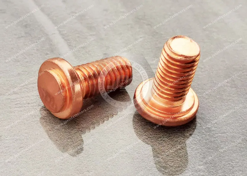
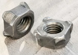
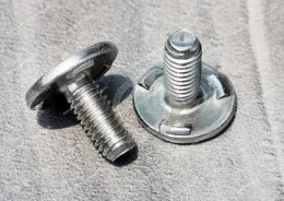
Capacitor discharge (CD) weld studs are fastening components designed for attachment to compatible metal substrates using a short-duration stud welding process powered by stored electrical energy.
They are widely considered for sheet metal assemblies where threaded mounting points must be added without drilling a through-hole or installing a separate nut.
Product Specification
Capacitor discharge (CD) weld studs are fastening components designed for attachment to compatible metal substrates using a short-duration stud welding process powered by stored electrical energy.
They are widely considered for sheet metal assemblies where threaded mounting points must be added without drilling a through-hole or installing a separate nut.
Potential applications include electrical enclosures, telecommunications cabinets, server chassis, industrial equipment housings,
HVAC components, elevator control panels, and precision fabricated sheet metal products.
For manufacturing engineers, CD stud welding offers an alternative to conventional drilling, tapping, mechanical fastening, and certain other welding methods.
The process can be particularly useful when minimizing thermal effects and maintaining the appearance of the opposite sheet surface are important design objectives.
However, successful CD stud welding depends on the interaction between the stud, base material, welding equipment, surface condition, and production parameters.
A suitable stud alone does not guarantee a satisfactory welded joint.
JUXIN FASTENERS supports international OEM sourcing inquiries for capacitor discharge weld studs and related drawing-based industrial fastening components.
This guide explains CD weld stud selection, material compatibility, welding parameters, installation considerations,
mechanical testing, production quality control, and procurement requirements for industrial applications.
A capacitor discharge weld stud is a stud designed for attachment using a capacitor-powered stud welding process.
The welding equipment stores electrical energy in capacitors and releases that energy during the welding cycle.
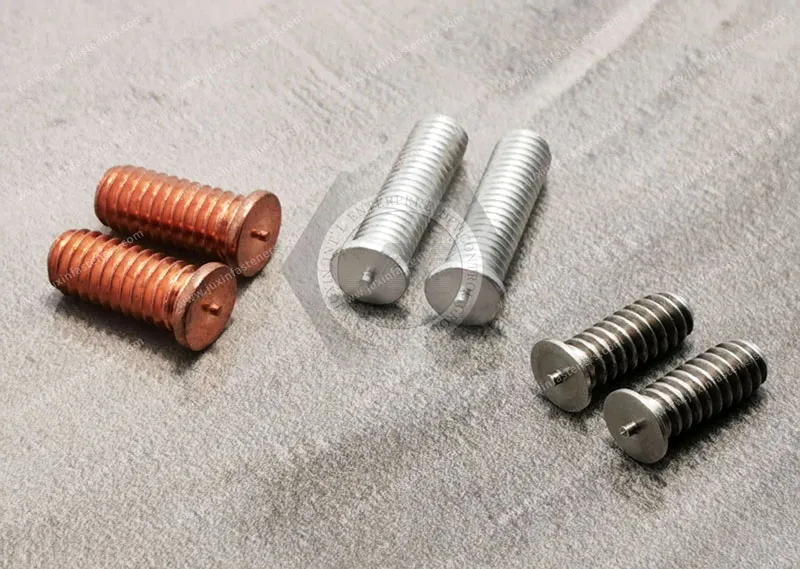
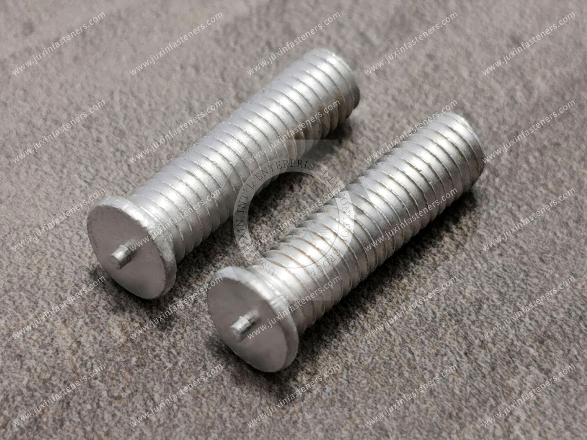
In a common tip-ignition CD stud welding process, the stud incorporates a small ignition tip at its welding end.
The ignition tip helps initiate the welding event when the stud contacts the workpiece under the appropriate equipment conditions.
The localized welding process forms a connection between the stud base and the parent metal.
Depending on the application and product design, CD weld fasteners may include:
Externally threaded studs.
Unthreaded pins.
Internally threaded mounting components.
Other purpose-designed CD welding fasteners.
This article focuses primarily on externally threaded CD weld studs.
When properly selected and qualified, CD stud welding may offer:
Rapid welding cycles.
Localized heat input.
No requirement for a conventional through-hole.
Reduced need for separate nuts.
Potentially limited backside marking.
Compatibility with suitable automated or semi-automated production.
Repeatable threaded attachment points.
Actual performance depends on the application and validated welding procedure.
These processes should not be treated as interchangeable.
CD welding uses energy stored in capacitors.
The process generally involves a short-duration welding event.
It is commonly considered for relatively thin sheet metal and applications where localized heat input is beneficial.
Drawn arc stud welding uses a different process in which an arc is established between the stud and workpiece.
Depending on the method and application, the process may involve longer arc duration, different equipment, and different weld preparation requirements.
Projection welding is a resistance welding process.
It uses concentrated contact regions or projections together with electrical current and electrode force.
Projection weld studs and nuts are therefore not automatically equivalent to tip-ignition CD weld studs.
| Process | Main Principle | Important Selection Factors |
|---|---|---|
| CD stud welding | Capacitor-powered stud welding | Stud tip, sheet thickness, surface condition, stored energy |
| Drawn arc stud welding | Arc-based stud welding | Stud geometry, arc control, material thickness, welding procedure |
| Projection welding | Resistance welding using localized contact features | Projection geometry, electrode force, current, material compatibility |
| Mechanical fastening | Threaded or deformed mechanical attachment | Hole geometry, access, assembly loading, installation equipment |
Choose the fastening process according to the complete assembly design, not solely the nominal stud diameter.
The geometry of a CD weld stud influences the welding process.
A tip-ignition stud incorporates a small feature at the welding end that participates in initiating the welding event.
The ignition tip must match the intended welding process and equipment.
The stud base geometry influences contact, heat distribution, and weld formation.
The relevant dimensions should be controlled according to the applicable product specification.
Certain stud configurations incorporate a flange or enlarged welding base.
The geometry must be suitable for the intended welding method.
A larger flange should not automatically be assumed to provide greater joint strength.
The threaded section must match the mating nut or component.
Important characteristics include:
Nominal diameter.
Thread pitch.
Thread tolerance.
Stud length.
Thread runout.
Surface condition.
For repeatable production, variations in ignition-tip geometry may influence weld initiation and consistency.
Critical tip dimensions should be defined and inspected where required.
Stud material selection must account for both mechanical requirements and welding compatibility.
Carbon steel CD weld studs are used in suitable industrial sheet metal applications.
The actual steel grade and surface condition should be specified.
Stainless steel CD weld studs may be considered for compatible stainless steel or other qualified substrate combinations.
Material selection should account for corrosion exposure, welding behavior, and joint requirements.
Aluminum CD weld studs may be suitable for compatible aluminum applications.
Aluminum welding requires particular attention to oxide layers, electrical and thermal characteristics, surface preparation, and equipment setup.
Joining dissimilar metals can introduce additional metallurgical and corrosion considerations.
Compatibility should be established through appropriate engineering evaluation and welding trials.
If material traceability or specific material documentation is required, it should be defined during the quotation and supplier qualification process.
The availability of particular certificates must be confirmed for the actual product.
The base material is a critical part of the welded joint.
Low-carbon steel sheet is commonly used in industrial enclosures and fabricated equipment.
The selected stud and welding parameters must be compatible with the actual material grade and surface condition.
Stainless steel substrates may require different welding settings and preparation compared with carbon steel.
The specific stainless steel grade and surface condition should be identified.
Aluminum has relatively high thermal and electrical conductivity.
Its oxide layer and material condition may affect welding consistency.
Suitable equipment, stud geometry, and process qualification are important.
Coatings can affect electrical contact, weld formation, and local surface behavior.
Pre-coated sheet should not automatically be considered suitable for CD stud welding.
The actual coating system and welding procedure must be evaluated.
Oil, paint, oxide, moisture, and other contamination may interfere with the welding process.
The required surface preparation depends on the materials and equipment.
One reason manufacturers consider CD stud welding is its potential suitability for relatively thin metal sheet.
However, minimum sheet thickness cannot be defined by one universal number.
The sheet must support the welding process and resulting mechanical loads.
Insufficient thickness may increase the risk of:
Burn-through.
Local distortion.
Backside marking.
Reduced joint performance.
Unacceptable surface appearance.
Stud diameter, weld-base geometry, material properties, and sheet thickness interact.
A larger stud does not automatically remain suitable for the same sheet thickness as a smaller stud.
CD welding can produce relatively localized thermal effects.
However, backside discoloration, marking, or distortion may still occur.
The extent depends on:
Material type.
Sheet thickness.
Surface finish.
Stud dimensions.
Welding energy.
Equipment setup.
Heat dissipation.
Welding directly onto a coated or painted panel may affect the coating and welding quality.
Where cosmetic or corrosion-protection requirements are important, the production sequence should be evaluated.
For thin sheet metal applications, perform welding trials using representative production material.
Evaluate both weld strength and acceptable backside appearance.
The electrical energy available for the welding process is an important parameter.
For an ideal capacitor, stored energy is expressed as:
E = ½CV²
Where:
E is stored energy in joules.
C is capacitance in farads.
V is capacitor voltage in volts.
Stored energy increases with capacitance.
For a fixed capacitance, stored energy increases with the square of the charging voltage.
Therefore, changing voltage can significantly change the available stored energy.
Stored capacitor energy is not the same as the exact energy delivered into the weld interface.
Actual energy transfer depends on equipment design, electrical losses, and process conditions.
Insufficient effective welding energy may contribute to:
Incomplete fusion.
Poor weld formation.
Inconsistent attachment.
Reduced mechanical performance.
Excessive energy may contribute to:
Excessive spatter.
Surface damage.
Unwanted melting.
Distortion.
Burn-through.
Irregular weld geometry.
A single voltage or joule value should not be prescribed for all CD weld studs.
The correct settings depend on the stud, substrate, equipment, and validated process.
The welding gun and its tooling influence weld consistency.
The collet holds and positions the stud.
A damaged, contaminated, or unsuitable collet may affect electrical contact and stud alignment.
The stud should be positioned according to the required assembly geometry.
Angular misalignment may affect weld formation and downstream assembly.
Certain CD welding systems use spring-controlled movement.
The relevant settings influence the stud's movement during the welding cycle.
The correct setup depends on the equipment and welding method.
The sheet must be adequately supported during welding.
Insufficient support may allow unwanted movement or distortion.
The welding equipment requires a suitable electrical return path.
Poor connections can affect welding consistency and create safety concerns.
Routine checks may include:
Collet wear.
Cable condition.
Electrical connections.
Gun alignment.
Spring mechanism.
Workpiece fixtures.
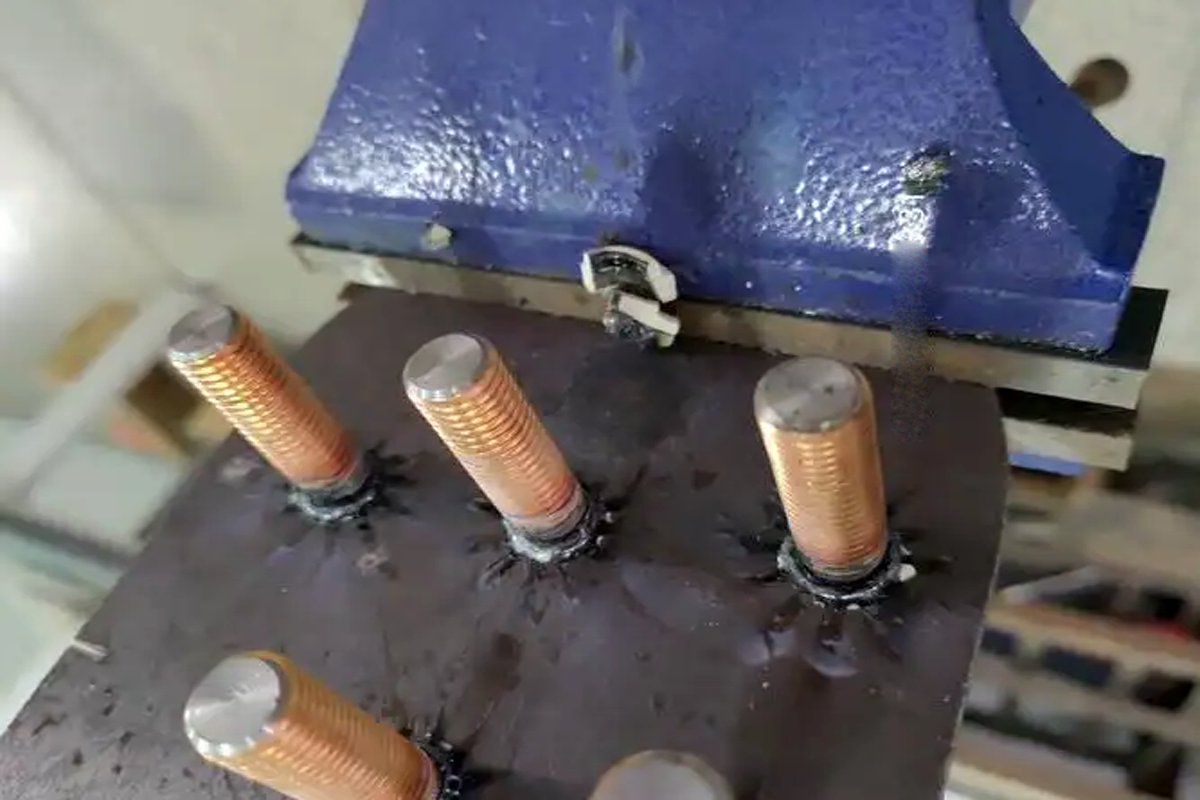
Weld appearance can provide useful process information, but appearance alone does not prove mechanical strength.
Depending on the process and geometry, molten metal may form around the weld base.
The acceptable appearance should be defined for the application.
Excessive spatter may indicate unsuitable process conditions or surface contamination.
Potential consequences include:
Cosmetic defects.
Thread contamination.
Local surface damage.
Additional cleaning operations.
An irregular or incomplete weld region may indicate inadequate process conditions.
Visual inspection may assess:
Stud position.
Perpendicularity.
Surface damage.
Excessive spatter.
Obvious weld irregularities.
Thread contamination.
A visually acceptable weld is not necessarily mechanically acceptable.
Functional testing is required where specified.
CD weld stud performance must be evaluated according to the actual assembly loading conditions.
Axial loads may act along the stud's longitudinal axis.
The resulting stress depends on the joint geometry and load path.
Shear loads act across the stud or joint.
The limiting failure mode may involve the stud, weld, or parent sheet.
A stud supporting a bracket or elevated component may experience bending moments.
Longer unsupported lengths can increase bending effects under lateral loading.
Tightening a nut on the stud introduces torque.
The weld must withstand the specified assembly process.
Possible failure modes include:
Failure within the stud.
Failure at the weld interface.
Parent sheet tearing.
Local sheet deformation.
Thread damage.
Joint loosening.
Do not select a CD weld stud solely from its nominal thread diameter.
Consider the complete load path, stud length, sheet thickness, material properties, and validated weld performance.
Mechanical testing should be selected according to the application and agreed acceptance criteria.
Bend testing may be used as part of weld procedure or production verification where appropriate.
The test method and acceptance requirements must be defined.
Tensile testing may be used to evaluate axial joint performance.
The test configuration influences the result.
Shear testing may be appropriate where the application involves lateral loading.
Torque testing may be used to evaluate the joint's resistance under specified rotational loading.
Destructive testing can provide information about mechanical performance and failure mode.
Nondestructive inspection may support dimensional or surface-quality verification.
The inspection plan should reflect the criticality of the application.
ISO 14555 provides requirements relevant to arc stud welding of metallic materials, including applicable stud welding processes.
ISO 13918 addresses studs and ceramic ferrules for arc stud welding.
The applicability of particular requirements must be checked against the specified process, product type, and edition of the standards.
Compliance with a stud dimension standard does not independently establish that a production weld meets its required strength.
Welding procedure qualification and production controls remain essential.
Before moving from prototype welding to volume production, the manufacturing process should be validated.
Trials should use representative:
Studs.
Parent sheet materials.
Sheet thicknesses.
Surface conditions.
Welding equipment.
Fixtures.
A suitable parameter window should be established through controlled trials.
Relevant parameters may include:
Capacitor charging voltage.
Equipment configuration.
Gun setup.
Stud movement.
Contact condition.
Workpiece support.
Acceptance criteria may include:
Weld appearance.
Stud position.
Perpendicularity.
Backside marking.
Mechanical test results.
Production consistency.
A change in stud material, sheet grade, coating, equipment, or welding setup may require reassessment.
Where required, records may document:
Approved welding parameters.
Equipment identification.
Inspection results.
Test samples.
Nonconformities.
Corrective actions.
For production managers, CD stud welding should be evaluated as part of the complete manufacturing process.
Manual systems may be appropriate for certain production volumes and assembly geometries.
Semi-automated equipment may support repeatable positioning and material handling.
Automated systems may be suitable for higher-volume applications where equipment and product geometry permit.
Automatic feeding compatibility depends on the stud design and equipment.
Important factors include:
Stud length.
Head or flange geometry.
Thread condition.
Surface finish.
Feeding orientation.
Fixtures may be used to control:
Stud position.
Workpiece support.
Perpendicularity.
Repeatability.
Operator access.
The total manufacturing cost may include:
Stud price.
Welding equipment.
Tooling.
Fixture preparation.
Welding cycle.
Inspection.
Rework.
Scrap.
Surface finishing.
Stable production requires control over both incoming stud quality and welding equipment conditions.
Possible causes:
Insufficient effective energy.
Surface contamination.
Incorrect stud material.
Incompatible substrate.
Poor electrical connection.
Unsuitable gun setup.
Recommended review:
Check the approved welding procedure, equipment, materials, and mechanical test results.
Possible causes:
Excessive effective energy.
Incorrect gun setup.
Surface contamination.
Unsuitable stud geometry.
Recommended review:
Inspect the welding parameters, stud tip, and workpiece condition.
Possible causes:
Excessive heat input.
Insufficient sheet thickness.
Unsuitable stud diameter.
Inadequate workpiece support.
Material or coating sensitivity.
Recommended review:
Evaluate the stud-to-sheet combination and qualified parameter window.
Possible causes:
Incorrect gun alignment.
Worn collet.
Uneven workpiece support.
Fixture movement.
Recommended review:
Inspect tooling and positioning accuracy.
Possible causes:
Material variation.
Surface contamination.
Stud tip variation.
Equipment condition.
Fixture inconsistency.
Recommended review:
Assess incoming material controls and process monitoring.
Possible causes:
Spatter contamination.
Incorrect collet.
Excessive mechanical handling.
Incorrect mating nut.
Cross-threading.
Recommended review:
Inspect the thread condition and downstream assembly process.
Electrical equipment manufacturers often require threaded mounting points on fabricated metal panels.
Potential applications include:
Internal equipment brackets.
Control panels.
Electrical cabinet assemblies.
Mounting plates.
Instrument supports.
Important requirements include:
Sheet thickness.
Stud positioning.
Mechanical loading.
Corrosion protection.
Electrical clearance.
Surface finish.
A welded metal stud does not independently establish a certified grounding or protective bonding connection.
Where electrical bonding is required, the complete design must be evaluated according to the applicable equipment requirements.
Telecommunications and server equipment often use compact sheet metal structures with multiple mounting points.
CD weld studs may be considered for:
Internal brackets.
Equipment mounting plates.
Chassis subassemblies.
Cable management supports.
Electronic module supports.
Engineers should evaluate:
Stud height.
Thread size.
Installation position.
Sheet distortion.
Backside appearance.
Assembly access.
Mechanical loading.
Power distribution and computing infrastructure may require repeatable metal enclosure assembly.
CD weld studs can be evaluated as one possible fastening method where the application geometry and manufacturing requirements are compatible.
CD weld studs may also be considered for suitable HVAC and industrial equipment components.
Potential applications include:
Sheet metal housings.
Equipment covers.
Mounting brackets.
Control compartments.
Internal supports.
Potential applications include:
Equipment panels.
Fabricated enclosures.
Instrument mounting.
Service covers.
Internal brackets.
Selection should consider:
Vibration.
Corrosion.
Temperature.
Mechanical loading.
Maintenance access.
Different fastening methods may provide similar mounting functions but require different manufacturing processes.
| Fastening Method | Installation Principle | Main Consideration |
|---|---|---|
| CD weld stud | Capacitor-powered stud welding | Welding compatibility, heat input, joint testing |
| Self-clinching stud | Pressed into compatible sheet metal | Sheet thickness, hardness and hole geometry |
| Rivet stud | Mechanically retained through a prepared hole | Hole design and setting requirements |
| Through-bolt and nut | Conventional mechanical fastening | Backside access and assembly handling |
| Projection weld stud | Resistance welding process | Projection geometry, electrode force and current |
CD weld studs may be appropriate when:
A threaded mounting point is required.
A through-hole is undesirable.
The substrate is weldable using the selected process.
Localized heat input is beneficial.
The welding process can be qualified.
Self-clinching studs may be suitable when the host sheet is compatible and a press installation process is preferred.
Mechanical fasteners may be appropriate where welding is undesirable or the assembly requires a different installation method.
The correct solution depends on the complete assembly design, manufacturing process, service environment, and quality requirements.
CD weld studs may use metric or Unified inch external threads, depending on the approved product design.
Examples of metric thread designations include:
M3 × 0.5.
M4 × 0.7.
M5 × 0.8.
M6 × 1.0.
M8 × 1.25.
These are thread designation examples, not a statement that every material and length is available.
Relevant standards include ISO 68-1, ISO 261, and applicable ISO 965 provisions.
UNC and UNF thread requirements may be specified according to ASME B1.1.
The actual available configurations must be confirmed.
M4 nominal diameter is approximately 0.1575 inches.
M5 nominal diameter is approximately 0.1969 inches.
M6 nominal diameter is approximately 0.2362 inches.
M8 nominal diameter is approximately 0.3150 inches.
These conversions are dimensional references only.
Metric threads are not directly interchangeable with UNC, UNF, BSW, or BSF threads.
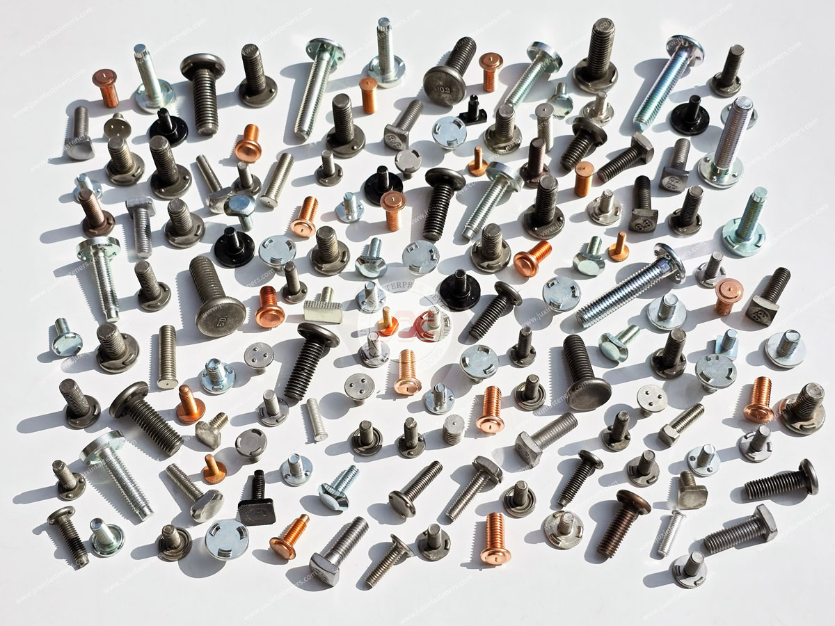
The approved stud drawing should define:
Thread designation.
Stud length.
Weld-base geometry.
Ignition-tip geometry.
Material.
Surface condition.
Critical tolerances.
For purchasing managers and supplier development teams, CD weld stud qualification should cover both product consistency and welding-process compatibility.
Confirm:
Nominal diameter.
Thread pitch.
Overall length.
Weld-base dimensions.
Ignition-tip geometry.
Thread tolerances.
Specify:
Material grade.
Mechanical properties, where required.
Surface condition.
Coating requirements.
Identify:
Parent sheet material.
Thickness range.
Coating condition.
Welding surface preparation.
Where available, provide:
Welding equipment type.
Welding method.
Stud feeding requirements.
Gun or collet restrictions.
Fixture limitations.
Define:
Dimensional inspection.
Material documentation.
Welding qualification requirements.
Mechanical test methods.
Acceptance criteria.
Lot traceability requirements.
Provide:
Prototype quantity.
Initial production quantity.
Estimated annual demand.
Packaging requirements.
Target lead time.
Delivery destination.
A replacement CD weld stud should not be approved solely because its thread diameter and length match an existing product.
Differences in ignition-tip geometry, material condition, weld-base dimensions, and surface treatment may affect the welding process.
Where necessary, the replacement should be evaluated using the customer's actual welding equipment and substrate.
Before approving a CD weld stud, verify the following.
Stud Geometry
Does the product drawing define the required thread, length, weld base, and ignition tip?
Material Compatibility
Is the stud material compatible with the parent sheet and welding process?
Sheet Thickness
Is the substrate suitable for the selected stud and process?
Surface Condition
Are the coating and surface preparation requirements defined?
Welding Equipment
Is the equipment suitable for the selected stud configuration?
Welding Parameters
Has an appropriate parameter window been established through trials?
Mechanical Performance
Does the completed joint satisfy the required loading conditions?
Backside Appearance
Does the welded panel meet cosmetic and dimensional requirements?
Production Consistency
Can the process maintain acceptable results during volume manufacturing?
Quality Documentation
Are the required inspection, testing, and traceability arrangements defined?
Commercial Requirements
Are quantity, packaging, delivery, and supplier qualification requirements clear?
A capacitor discharge weld stud is a stud designed for attachment to a compatible metal substrate using a capacitor-powered stud welding process.
They may be suitable for relatively thin sheet metal, depending on stud geometry, material, equipment, and validated welding parameters.
Not universally. Backside appearance depends on the application and welding conditions.
CD stud welding uses capacitor-stored energy in a stud welding process. Projection welding is a resistance welding process using localized contact features.
Suitable CD weld studs may be used with compatible stainless steel substrates and qualified welding procedures.
Potentially, where the stud, substrate, equipment, and process are compatible.
There is no universal voltage setting. Parameters must be developed for the specific equipment and application.
Possible causes include inadequate effective energy, surface contamination, incompatible materials, and unsuitable equipment setup.
Inspection may include dimensional checks, visual examination, and specified mechanical tests.
Certain designs may be compatible with automated feeding systems, depending on equipment and component geometry.
No. They use different installation processes and require different substrate and equipment considerations.
No. The mating thread system must match the specified assembly.
Provide the stud drawing, material, thread designation, length, substrate specifications, welding process requirements, quantity, and delivery details.
JUXIN FASTENERS supports international B2B sourcing inquiries for capacitor discharge weld studs, weld pins, and related drawing-based industrial fastening components.
For electrical enclosures, telecommunications cabinets, server chassis, HVAC equipment, industrial machinery, and precision sheet metal assemblies,
correct stud selection helps support reliable welding and consistent manufacturing.
For a technical review or commercial RFQ, please provide:
2D engineering drawing or 3D CAD model.
Required CD weld stud configuration.
External thread designation and pitch.
Metric, UNC, UNF, or other specified thread system.
Stud length and critical dimensions.
Weld-base geometry.
Ignition-tip requirements.
Stud material grade.
Surface condition or coating specification.
Parent sheet material grade.
Sheet thickness.
Existing welding equipment and process information, where available.
Welding position and assembly geometry.
Backside appearance requirements.
Mechanical loading conditions.
Required weld testing and acceptance criteria.
Dimensional inspection requirements.
Material and traceability documentation requirements.
Prototype or sample quantity.
Initial production order quantity.
Estimated annual purchasing volume.
Packaging requirements.
Target delivery schedule and destination.
For nonstandard CD weld stud geometry or custom welding fastener requirements, please submit the relevant engineering drawings for feasibility review.
Our team can review the submitted technical and commercial requirements to confirm applicable product sourcing, manufacturing feasibility, and quotation arrangements.
Company: JUXIN FASTENERS
Website: www.juxinfasteners.com
Email: info@juxinfasteners.com
Contact JUXIN FASTENERS with your drawings, substrate specifications, and purchasing requirements to request a quotation for capacitor discharge weld studs and related OEM industrial fastening components.
Product Packaging
Packaging Standard
At Juxin Fasteners, we apply standardized export packaging to ensure product protection, traceability, and compliance with international logistics requirements.
1. Standard Export Packaging
Unless otherwise specified, all products will be packed according to our factory standard export packaging, which includes:
Moisture-resistant inner protection
Poly bag or small box packing as required
Reinforced export cartons
Clear labeling with part number, specification, batch number, and quantity
Palletizing for sea or air shipment when necessary
Our standard packaging is designed to ensure safe transportation, efficient warehousing, and long-distance international shipping.
2. Customized Packaging Options
We also provide customized packaging solutions according to customer requirements, including but not limited to:
Private labeling
Customized barcodes
Specific carton dimensions
Retail packaging
Special pallet configuration
Customer-specific marking and identification
So that you know, customized packaging may involve additional costs and extended lead time depending on the complexity of the requirements.
3. Compliance & Quality Assurance
All packaging processes are controlled under our ISO 9001 quality management system to ensure consistency, traceability, and product integrity throughout the supply chain.
Product Pictures

Contact Us
Tel.:
+86 020 8621 0320
+86 020 3121 6067
E-mail:
Technical Support:
Navigation
SEND INQUIREY