Call Us
+86 136 6007 9809
Call Us
+86 136 6007 9809

What is the minimum edge distance required when placing weld fasteners on sheet metal?
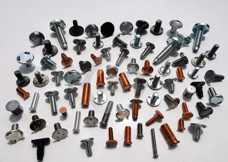
There is no single universal minimum edge-distance value that applies to every weld nut, weld stud, sheet thickness, material combination, and projection-welding process.
Product Specification
What is the minimum edge distance required when placing weld fasteners on sheet metal?
There is no single universal minimum edge-distance value that applies to every weld nut, weld stud, sheet thickness, material combination, and projection-welding process.
For resistance-welded fasteners, edge distance should be treated as an application-specific DFM parameter.
The distance from the fastener, weld projections, or pilot feature to the free edge of the sheet must provide sufficient surrounding parent metal for stable current flow, electrode access,
heat distribution, mechanical support, and containment of the weld zone.
Placing a weld nut or weld stud too close to a sheet edge can increase the risk of edge deformation, weld expulsion, incomplete or asymmetric nugget formation, local overheating,
and reduced parent-metal strength. The appropriate design value should therefore be validated against the fastener geometry, projection arrangement,
sheet material, sheet thickness, welding equipment, electrode configuration, and required joint performance.
A simplified DFM concept is:
        <----------- Edge Distance ----------->

        Sheet Free Edge
        |
        |-----------------------------------------------|
        |                                               |
        |              +-------------------+            |
        |              |     WELD NUT      |            |
        |              +-------------------+            |
        |                   Weld Zone                  |
        |                                               |
        |-----------------------------------------------|

        Edge distance should provide sufficient
        surrounding parent metal for the welding
        process and required mechanical performance.
The important engineering question is therefore not simply “Is the fastener more than a certain multiple of the hole diameter from the edge?” but rather:
“Does the available surrounding sheet area provide adequate welding process stability and structural support for this specific fastener and application?”
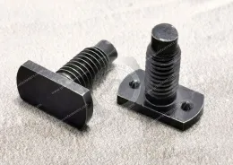
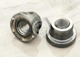
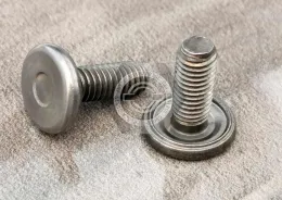
For JUXIN FASTENERS, weld fastener placement should be evaluated as part of the complete joint design rather than as an isolated dimensional rule.
Fastener geometry, projection configuration, sheet material, thickness, electrode access, hole or pilot requirements, and production welding conditions should be considered together during DFM review.
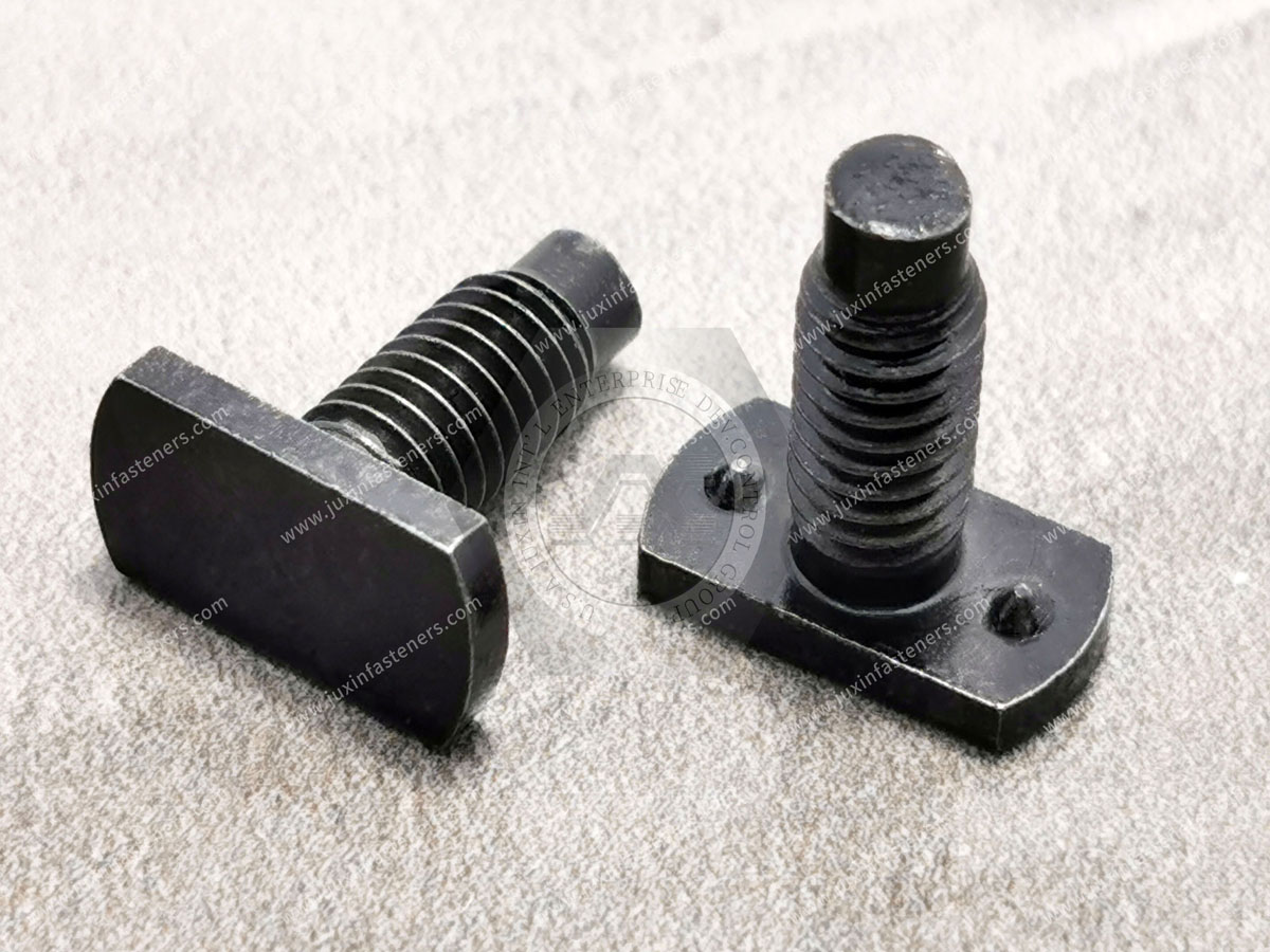
When a weld fastener is positioned close to a free sheet edge, the surrounding parent metal becomes less capable of supporting the thermal and mechanical conditions generated during welding.
Several effects can occur simultaneously:
Reduced thermal mass: Less material exists around the weld zone to absorb and distribute heat.
Altered current distribution: The electrical current path can become less symmetrical when the weld zone is close to a free edge.
Reduced mechanical support: A narrow strip of sheet metal may deform more easily under electrode force or subsequent service loads.
Increased risk of expulsion: Localized overheating and unstable contact conditions can contribute to expulsion.
Edge distortion: Heat and electrode force can cause local deformation of unsupported sheet metal.
Reduced structural margin: Even when the weld itself is sound, insufficient surrounding parent metal may become the limiting factor in the finished joint.
For these reasons, edge distance is both a welding-process consideration and a structural-design consideration.
A common mistake in sheet metal DFM is to define edge distance solely according to the weld fastener's physical size.
The fastener may physically fit close to an edge while the finished joint remains unsuitable for production.
The design must also consider:
Weld projection geometry
Electrode contact area
Current path
Sheet thickness
Parent-metal strength
Fastener size and geometry
Required weld strength
Applied mechanical loads
Stamping tolerances
Welding fixture accuracy
Electrode accessibility
Potential sheet deformation
Therefore, the recommended edge distance should come from the complete joint design and process validation, not from one generic ratio.
Where the weld fastener incorporates a pilot, locating feature, or hole-related geometry, the mating sheet opening should be designed according to the specific fastener drawing and installation process.
The hole should provide reliable positioning without creating excessive clearance that could affect fastener location or welding consistency.
Gemini's original recommendation of maintaining every pilot hole within a universal ±0.1 mm tolerance should not be treated as a general industry rule.
Actual dimensional requirements can depend on:
Fastener pilot diameter
Sheet thickness
Stamping or laser-cutting process
Required positional accuracy
Fastener self-location features
Welding fixture design
Assembly tolerances
OEM drawing requirements
For production tooling, the final hole specification should therefore be established from the approved fastener drawing and the manufacturing capability of the sheet-metal process.
An excessively large hole or poorly controlled locating feature can create additional problems.
Depending on the fastener design, excessive clearance may:
Reduce positional repeatability
Allow fastener movement before welding
Change the intended current path
Reduce consistency between individual weld locations
Increase fixture dependence
Create assembly-location variation
The objective is not simply to make the fastener fit into the hole. The objective is to achieve repeatable positioning and stable welding conditions throughout production.
When the weld zone is positioned close to a free edge, the electrical current distribution around the welding area may become less symmetrical.
The available parent metal around the weld zone is reduced, and the current path can be influenced by the nearby free surface.
This may contribute to:
Localized heating
Uneven nugget development
Edge-side expulsion
Local sheet deformation
Reduced weld consistency
However, this phenomenon should not automatically be described as “magnetic blow” in every edge-related weld defect.
Magnetic effects can influence resistance welding under certain electrical and geometric conditions,
but many edge-related defects are better understood through the broader interaction of current distribution, thermal balance, electrode force, sheet geometry, and mechanical support.
That distinction is important when diagnosing production failures.
Sheet thickness is one of the important variables when determining whether a weld fastener can safely be positioned near an edge.
A thin sheet has less material available around the weld zone and may therefore be more sensitive to:
Local heating
Burn-through
Edge deformation
Projection collapse behavior
Parent-metal tearing
Local buckling or distortion
A thicker sheet generally provides greater surrounding material, but this does not mean that thicker sheet automatically eliminates edge-distance concerns.
Thicker material can change the welding heat balance and current path, while the fastener projection geometry and electrode configuration remain important.
Therefore, the design relationship should be considered conceptually as:
Fastener Geometry
        +
Projection Geometry
        +
Sheet Thickness
        +
Sheet Material
        +
Edge Distance
        +
Electrode Configuration
        +
Welding Parameters
        =
Validated Weld Joint
This is more reliable than applying one fixed thickness-to-edge-distance formula to every application.
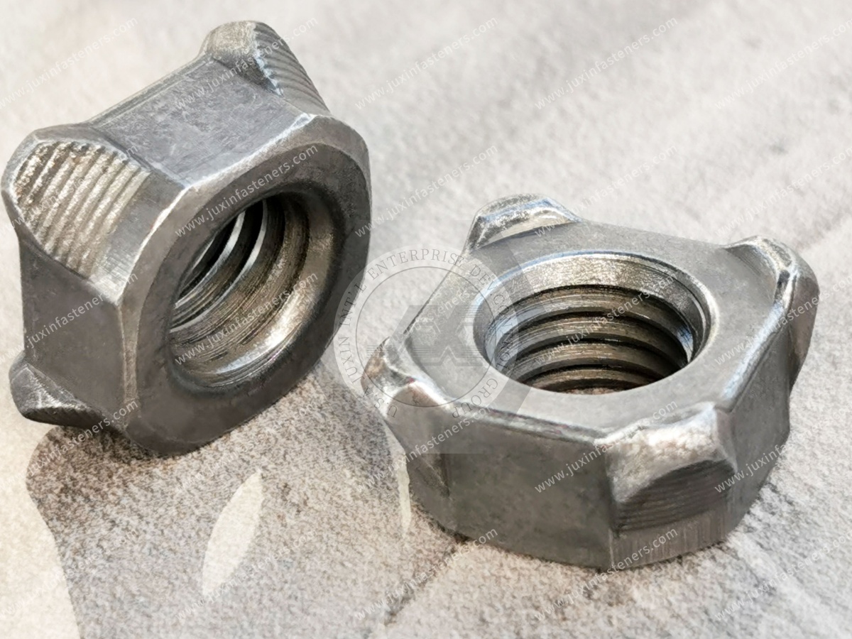
When placing a weld nut near a sheet edge, engineers should evaluate the complete geometry around the fastener.
The sheet should provide enough surrounding parent material to support the weld area and the mechanical loads transferred through the fastener.
If the edge is too close, the sheet may become the weak link even when the weld itself is properly formed.
For example, under torque applied to a welded nut, the joint does not depend only on the weld nugget. The surrounding sheet must also resist deformation and failure.
A theoretically acceptable fastener position may still be difficult to weld if the electrode cannot contact the joint correctly.
The design should therefore consider:
Electrode diameter and face geometry
Electrode approach direction
Clearance from nearby flanges
Nearby bends
Adjacent welds
Tooling access
Fixture restrictions
Robot or automated welding path
This is particularly important in automotive, appliance, electrical enclosure, and fabricated sheet-metal assemblies where multiple geometric features may compete for the same workspace.
A weld fastener positioned close to a sheet bend may experience additional geometric and process constraints.
The bend can affect:
Electrode accessibility
Local sheet stiffness
Current path
Heat dissipation
Fastener seating
Post-weld dimensional stability
The correct location should therefore be evaluated against the entire stamped or formed component rather than only the flat-pattern drawing.
Edge distance is only one part of weld fastener placement.
The spacing between adjacent weld fasteners and other resistance-welded features should also be evaluated.
If multiple weld locations are positioned too closely together, their thermal and electrical conditions may interact.
Potential concerns include:
Current shunting
Overlapping heat-affected regions
Uneven current distribution
Reduced process repeatability
Difficulty maintaining electrode access
Local sheet distortion
The appropriate spacing depends on the fastener design, weld configuration, sheet material and thickness, welding sequence, and equipment.
For this reason, weld fastener spacing should be validated rather than reduced to a universal numerical rule.
Weld expulsion near a sheet edge can occur when the welding process becomes unstable.
Possible contributing factors include:
Excessive welding current for the joint condition
Insufficient or unstable electrode force
Inconsistent projection geometry
Poor surface condition
Improper electrode alignment
Excessive local resistance
Insufficient surrounding sheet material
Poor fastener seating
Inappropriate welding schedules
When the weld location is close to an edge, the reduced surrounding parent metal can make the consequences of unstable welding more severe.
A useful troubleshooting approach is therefore:
Edge-Related Weld Defect
          |
          v
Check Fastener Position
          |
          v
Check Sheet Thickness & Material
          |
          v
Check Projection Geometry
          |
          v
Check Electrode Alignment & Access
          |
          v
Check Welding Current / Force / Time
          |
          v
Check Surface Condition
          |
          v
Destructive Weld Validation
This approach prevents engineers from assuming that the edge distance itself is always the sole cause of the defect.
Before releasing a weld-fastened sheet-metal component for production, engineers should review the following:
Is the weld fastener sufficiently supported by surrounding parent metal?
Is the fastener positioned away from vulnerable free edges?
Is the fastener clear of bends, flanges, holes, and other formed features?
Is there sufficient clearance for the welding electrode?
Is the fastener location compatible with the assembly sequence?
Is the weld nut or weld stud geometry suitable for the sheet material?
Are the projections consistent with the intended welding process?
Is the fastener orientation correct?
Are the locating features compatible with the sheet opening?
Can the electrodes reach the joint correctly?
Is the current path appropriate for the joint geometry?
Is electrode force distributed consistently?
Have current, weld time, and force been validated for the actual material combination?
Has the process been evaluated for expulsion and distortion?
Has sample welding been completed using production-representative conditions?
Have destructive tests been performed where appropriate?
Has the actual failure mode been identified?
Does the parent metal remain structurally adequate around the weld?
Are dimensional and positional tolerances maintained after welding?
Consider a weld nut positioned near the edge of a stamped steel bracket.
A simple dimensional inspection may show that the nut physically fits within the available area.
However, production validation should examine more than physical fit.
The engineer should evaluate:
Step 1 — Fastener Geometry
Determine the weld nut's outside dimensions, projection arrangement, pilot requirements, and electrode contact requirements.
Step 2 — Sheet Geometry
Review sheet thickness, material grade, edge shape, nearby holes, bends, flanges, and formed features.
Step 3 — Edge Support
Confirm that sufficient parent metal surrounds the weld zone to support both welding and the intended mechanical loading.
Step 4 — Welding Access
Confirm that the electrode can approach the fastener without contacting adjacent geometry.
Step 5 — Process Validation
Establish welding parameters for the actual fastener and sheet combination rather than transferring an unverified parameter set from another joint.
Step 6 — Mechanical Validation
Test the finished joint using the performance criteria relevant to the application, such as torque resistance, push-out behavior, tensile loading, or other customer-defined requirements.
This process creates a much stronger DFM foundation than simply checking whether a fastener is a certain distance from the edge.
A fixed rule such as “edge distance must always equal 2.5 × hole diameter” may be useful as a preliminary design reference in a particular engineering standard or fastener system,
but it should not automatically be presented as a universal resistance-welding requirement.
The actual acceptable value can vary with:
Weld nut or weld stud design
Projection count and geometry
Sheet thickness
Sheet material
Surface condition
Welding current
Electrode force
Electrode configuration
Required joint strength
Production tolerances
Component geometry
Load direction
Therefore, a responsible engineering specification should identify the applicable standard, fastener manufacturer's recommendation, or validated production condition behind any numerical edge-distance requirement.
For OEM programs, this is particularly important because a design that works on one sheet material or thickness may not behave identically on another.
For production applications, dimensional inspection alone is not sufficient to confirm that edge-distance design is adequate.
A quality-control program may combine:
Verify:
Fastener position
Edge distance
Hole dimensions
Fastener orientation
Sheet thickness
Critical component dimensions
Look for:
Edge deformation
Visible expulsion
Surface burning
Poor fastener seating
Electrode contact abnormalities
Abnormal weld appearance
Where required by the application, destructive testing can help determine whether the actual joint fails through:
Weld interface separation
Nugget failure
Parent-metal tearing
Sheet deformation
Fastener deformation
The objective is not merely to determine whether the weld “looks good,” but to identify the actual load path and failure mode of the finished joint.
Pillar Solution Page: JUXIN FASTENERS Weld Fasteners Solutions
Engineering Guide: Projection Welding Process & DFM Joint Optimization
Engineering Guide: Weld Nut Spin Failure Analysis & Prevention
Engineering Guide: Weld Stud Push-Out & Pull-Out Failure Analysis
Product Category Page: JUXIN FASTENERS Projection Weld Nuts
Product Category Page: JUXIN FASTENERS Projection Weld Studs
Commercial Sourcing Page: Contact JUXIN FASTENERS Engineering
A: There is no single universal minimum value that applies to every weld nut application. The required edge distance depends on the nut geometry,
projection configuration, sheet material and thickness, welding process, electrode access, and required mechanical performance.
Use the applicable fastener specification or validated engineering design rather than assuming one fixed ratio.
A: It may be possible in some application-specific designs, but proximity to the free edge reduces the surrounding parent-metal area and
can increase the sensitivity of the joint to heat, electrode force, current distribution, and mechanical loading. Such designs should be validated before production release.
A: Yes. Sheet thickness changes thermal behavior, mechanical support, and the available parent-metal section around the weld zone.
A placement that performs adequately in one sheet thickness may require reevaluation when the material or thickness changes.
A: No. Edge-related weld defects can result from several interacting factors, including current distribution, thermal balance, electrode force, projection geometry,
sheet thickness, and component geometry. Magnetic effects can be relevant in certain resistance-welding conditions, but they should not automatically be identified as the cause of every edge defect.
A: No. Hole tolerance should be based on the specific fastener drawing, locating method, sheet-metal manufacturing process, and required assembly accuracy.
A universal ±0.1 mm requirement should not be applied without engineering justification.
A: Review the fastener and sheet geometry first, then validate electrode access, welding conditions, dimensional stability,
and the required mechanical performance using production-representative samples. Destructive testing can be used to determine the actual joint failure mode when appropriate.
If your weld nut or weld stud must be positioned close to a sheet edge, flange, bend, hole, or other geometric feature, early DFM review can help identify potential welding and structural risks before tooling and mass production.
Send your 2D engineering drawings, CAD files, sheet material specifications, thickness, weld fastener requirements, and annual production quantities to our engineering team.
EMAIL: info@juxinfasteners.com
JUXIN FASTENERS supports OEM customers with weld fastener selection, DFM evaluation, custom fastener development, sample validation, and production supply for industrial sheet-metal applications.
The goal is not simply to place a weld fastener on a drawing.
The goal is to develop a repeatable, manufacturable, and mechanically reliable fastening joint that can move successfully from engineering design to high-volume production.
Product Packaging
Packaging Standard
At Juxin Fasteners, we apply standardized export packaging to ensure product protection, traceability, and compliance with international logistics requirements.
1. Standard Export Packaging
Unless otherwise specified, all products will be packed according to our factory standard export packaging, which includes:
Moisture-resistant inner protection
Poly bag or small box packing as required
Reinforced export cartons
Clear labeling with part number, specification, batch number, and quantity
Palletizing for sea or air shipment when necessary
Our standard packaging is designed to ensure safe transportation, efficient warehousing, and long-distance international shipping.
2. Customized Packaging Options
We also provide customized packaging solutions according to customer requirements, including but not limited to:
Private labeling
Customized barcodes
Specific carton dimensions
Retail packaging
Special pallet configuration
Customer-specific marking and identification
So that you know, customized packaging may involve additional costs and extended lead time depending on the complexity of the requirements.
3. Compliance & Quality Assurance
All packaging processes are controlled under our ISO 9001 quality management system to ensure consistency, traceability, and product integrity throughout the supply chain.
Product Pictures
Contact Us
Tel.:
+86 020 8621 0320
+86 020 3121 6067
E-mail:
Technical Support:
Navigation
SEND INQUIREY