Call Us
+86 136 6007 9809
Call Us
+86 136 6007 9809

Which metal substrates are compatible with resistance weld fasteners?
Resistance weld fasteners can be used with a broad range of metallic substrates,
but successful welding depends on much more than simply matching the fastener alloy to the sheet alloy.
Product Specification
Which metal substrates are compatible with resistance weld fasteners?
Resistance weld fasteners can be used with a broad range of metallic substrates, but successful welding depends on much more than simply matching the fastener alloy to the sheet alloy.
Low-carbon steels, stainless steels, HSLA steels, and other weldable sheet-metal grades can all be used in resistance-welded fastener applications when the fastener material,
projection geometry, substrate condition, electrode system, and welding schedule are appropriately matched and validated.
The key engineering variables include:
Electrical resistivity of the fastener and substrate
Thermal conductivity
Melting and softening behavior
Carbon and alloy content
Sheet thickness
Surface condition and coatings
Projection geometry
Electrode force
Welding current and time
Required mechanical performance
Potential metallurgical reactions at the interface
A simplified material-selection concept is:
              FASTENER MATERIAL
                     +
             PROJECTION GEOMETRY
                     +
              SHEET MATERIAL
                     +
              SHEET THICKNESS
                     +
             SURFACE / COATING
                     +
             WELDING PARAMETERS
                     |
                     v
          VALIDATED WELD JOINT
A material that is generally considered weldable does not automatically produce a reliable weld-fastener joint under every production condition.
For example, a low-carbon steel weld nut welded to a low-carbon steel sheet can offer a relatively straightforward resistance-welding combination.
Stainless steel introduces different electrical and thermal characteristics, while high-strength steels can introduce additional concerns related to heat-affected-zone behavior and local material properties.
JUXIN FASTENERS approaches substrate compatibility as a complete joint-engineering problem. Fastener material, sheet grade, thickness, surface condition, projection design, welding process, and required performance should be considered together during OEM DFM and sourcing evaluation.
Resistance welding generates heat primarily through the electrical resistance of the joint while mechanical force maintains contact between the components.
The fundamental relationship is commonly expressed as:
Q = I²Rt
where:
Q represents generated heat,
I represents welding current,
R represents electrical resistance within the relevant current path,
t represents the effective welding time.
This relationship explains why changing the substrate material can require a different welding process.
Two materials with different electrical resistivity or thermal conductivity may not respond identically to the same current and time.
Therefore, welding schedules should not simply be copied from one material combination to another without validation.
Low-carbon steels are widely used in resistance welding because they generally provide favorable electrical and metallurgical characteristics for conventional resistance-welding processes.
Typical examples can include low-carbon sheet grades used in:
Automotive components
Appliance panels
Electrical enclosures
Industrial equipment
General fabricated sheet-metal assemblies
When a compatible low-carbon steel weld nut or weld stud is joined to a suitable low-carbon steel sheet, the materials can provide a relatively predictable resistance-welding system.
However, even within the low-carbon-steel family, the actual result depends on:
Steel grade
Sheet thickness
Surface coating
Surface cleanliness
Fastener projection geometry
Electrode configuration
Welding schedule
Therefore, the term “low-carbon steel” should not be treated as a guarantee of identical welding behavior across all grades and conditions.
Stainless steel can also be used with resistance weld fasteners, but its electrical, thermal, and metallurgical characteristics differ from conventional carbon steel.
For example, austenitic stainless steels such as 304 and 316 have different electrical resistivity and thermal conductivity characteristics from low-carbon steel.
This can influence:
Heat generation
Heat distribution
Projection collapse
Electrode requirements
Welding-current requirements
Surface behavior
Electrode wear
Consequently, a welding schedule developed for carbon steel should not automatically be transferred to stainless steel.
The fastener material should also be selected according to the corrosion environment and required joint performance.
High-Strength Low-Alloy (HSLA) and Advanced High-Strength Steel (AHSS) substrates require additional engineering consideration.
The increased strength of these materials does not necessarily mean that resistance welding is unsuitable.
Instead, engineers should evaluate the effect of the welding thermal cycle on:
Weld nugget formation
Heat-affected-zone properties
Local hardness
Ductility
Fracture behavior
Parent-metal failure modes
Depending on the steel grade and welding conditions, rapid thermal cycles can alter local microstructure.
This is one reason why high-strength sheet applications should be validated using the actual material grade and production-representative welding conditions.
The following matrix should be treated as an engineering starting point rather than a universal weldability certification.
| Fastener / Substrate Combination | General Compatibility Consideration | Engineering Evaluation |
|---|---|---|
| Low-carbon steel fastener + low-carbon steel sheet | Generally favorable for conventional resistance welding | Validate projection geometry, thickness, coating, and welding schedule |
| Low-carbon steel fastener + HSLA steel sheet | Potentially suitable | Evaluate heat-affected-zone behavior and joint failure mode |
| Steel fastener + AHSS sheet | Application dependent | Requires process validation using actual grade and thickness |
| Stainless steel fastener + stainless steel sheet | Potentially suitable | Evaluate electrical, thermal, corrosion, and electrode conditions |
| Steel fastener + stainless steel sheet | Possible in selected applications | Evaluate dissimilar-material metallurgy, corrosion, and welding process |
| Coated steel sheet + weld fastener | Highly dependent on coating system | Verify coating behavior and production welding process |
| Aluminum substrate + conventional steel weld fastener | More challenging | Requires dedicated process and material evaluation |
The important point is that “compatible” does not mean “drop-in interchangeable.”
A material combination may be technically weldable while still requiring changes to projection geometry, welding parameters, surface preparation, electrode configuration, or corrosion protection.
Carbon equivalent (CE) calculations can be useful when evaluating the weldability and hardening tendency of certain steels.
However, the original statement that resistance weld fasteners should only be used when:
CE < 0.35
should not be treated as a universal resistance-welding requirement.
Different carbon-equivalent formulas exist for different engineering purposes, and their usefulness depends on the material system and welding process being evaluated.
For resistance welding, engineers should consider the complete material composition and thermal cycle rather than using one CE threshold as an automatic acceptance criterion.
Factors can include:
Carbon content
Alloying elements
Steel grade
Cooling behavior
Welding heat input
Sheet thickness
Joint geometry
Required mechanical performance
For high-strength or higher-alloy materials, material-specific welding recommendations and production validation are more reliable than applying an isolated CE number.
Resistance welding depends heavily on the electrical and thermal characteristics of the joint.
Materials with different electrical resistivity can produce different heat-generation behavior under the same welding current.
This affects the location and magnitude of heat generation within the joint.
For this reason, changing from carbon steel to stainless steel, aluminum, or another alloy may require process re-development.
Thermal conductivity determines how quickly heat moves away from the welding zone.
A highly conductive substrate can dissipate heat differently from a lower-conductivity steel sheet.
This can influence:
Nugget growth
Projection collapse
Heat-affected-zone size
Required energy input
Local sheet heating
Electrode cooling requirements
The fastener and substrate should be considered as one thermal system.
An extremely large fastener projection attached to a very thin sheet, for example, may create a poor thermal balance even when both materials are individually weldable.
Likewise, a heavy sheet can behave as a substantial heat sink and change the projection-welding response.
This is why material selection and projection design should be reviewed together.
Material grade alone does not determine resistance-welding behavior.
The condition of the sheet surface can have a major effect on contact resistance and welding consistency.
Potential surface conditions include:
Bare steel
Galvanized steel
Zinc-coated steel
Stainless steel surfaces
Aluminum surfaces
Organic coatings
Oils and forming lubricants
Oxides
Contaminants
Coated steel can be used in resistance-welded assemblies, but the coating system must be considered during process development.
The coating can influence:
Contact resistance
Electrode wear
Expulsion behavior
Surface appearance
Welding current requirements
Electrode contamination
The appropriate welding process therefore depends on the specific coating type and production condition.
Oil, oxides, dirt, excessive scale, or other contaminants can alter the electrical contact between the fastener and substrate.
This can lead to inconsistent welding conditions.
The solution is not necessarily to remove every trace of process lubricant. Instead, the surface condition should be compatible with the welding process and controlled consistently in production.
The original Gemini version stated that carbon-steel weld nuts should not be welded to stainless steel because dissimilar-metal welding creates galvanic corrosion and metallurgical embrittlement.
That is too absolute.
Dissimilar materials can be resistance welded in certain engineered applications, but the joint requires additional evaluation.
Important considerations include:
Different alloys can produce substantially different resistance and heat-transfer behavior.
The welding schedule must therefore be developed for the actual combination rather than copied from a same-material joint.
Depending on the materials involved, the weld interface may develop intermetallic phases, altered microstructures, or other metallurgical features that affect joint performance.
The significance depends strongly on the particular material pair and process conditions.
When dissimilar metals are exposed to an electrolyte, galvanic corrosion can become a design consideration.
This is especially relevant in:
Automotive exterior applications
Marine equipment
Outdoor electrical equipment
Battery systems
Humid environments
Applications involving road salt or other corrosive exposure
The corrosion risk should be evaluated together with coating systems, environmental exposure, joint geometry, and electrical isolation requirements.
For critical OEM applications, engineers should evaluate the finished joint rather than relying only on material compatibility tables.
Potential validation methods can include:
Tensile testing
Torque testing
Shear testing
Metallographic examination
Corrosion testing
Environmental exposure testing
Production-line weld validation
Different industries may prioritize different material properties.
Automotive sheet-metal assemblies frequently use combinations of:
Low-carbon steels
High-strength steels
AHSS
Galvanized or coated sheet
Weld fastener selection should consider the body structure, corrosion-protection process, welding sequence, and final mechanical requirements.
Electrical cabinets and enclosures may use:
Mild steel
Galvanized steel
Stainless steel
Aluminum
The correct weld fastener material and surface treatment depend on corrosion requirements, enclosure construction, electrical considerations, and finishing process.
Industrial equipment may combine thicker steel sheets with high mechanical loading.
Here, engineers should evaluate:
Fastener strength
Parent-metal strength
Weld integrity
Fatigue loading
Corrosion protection
Manufacturing process
Battery enclosures and energy equipment may involve aluminum, coated steel, stainless steel, or high-strength sheet materials.
Material selection should consider:
Thermal conditions
Corrosion environment
Electrical isolation
Joint loading
Manufacturing sequence
Compatibility with coatings and finishes
A weld fastener that performs well in conventional carbon-steel fabrication should not automatically be specified for a battery enclosure or aluminum structure without application-specific validation.
A practical OEM material-selection process can follow these steps:
Step 1
Identify substrate alloy and exact grade
        |
        v
Step 2
Confirm sheet thickness and surface condition
        |
        v
Step 3
Select compatible weld fastener material
        |
        v
Step 4
Review electrical and thermal characteristics
        |
        v
Step 5
Review projection and electrode configuration
        |
        v
Step 6
Develop application-specific welding parameters
        |
        v
Step 7
Validate weld integrity and failure mode
        |
        v
Step 8
Validate corrosion / environmental requirements
        |
        v
Step 9
Release production specification
This workflow helps prevent a common sourcing mistake: selecting a weld fastener based only on nominal material grade while overlooking the actual welding environment.
When the substrate material changes, the welding process should be reassessed.
A production validation program may include:
Confirm:
Actual substrate grade
Fastener material
Sheet thickness
Surface coating
Heat-treatment condition where relevant
Confirm:
Projection geometry
Electrode configuration
Welding current
Welding time
Electrode force
Cooling conditions
Production cycle
The exact parameter values should be established for the specific material combination rather than treated as universal settings.
Depending on the application, testing may include:
Push-out testing
Pull-out testing
Torque-out testing
Tensile testing
Shear testing
Fatigue evaluation
The test result should identify how the joint failed.
Possible failure modes include:
Weld interface separation
Nugget failure
Parent-metal tearing
Sheet deformation
Fastener deformation
Local cracking
The failure mode often provides more useful engineering information than a single ultimate-force number.
For procurement managers, material compatibility should be translated into clear purchasing requirements.
An OEM RFQ should ideally identify:
Fastener type
Fastener material
Required material grade where specified
Substrate material grade
Sheet thickness
Surface coating
Welding process
Applicable standards
Required mechanical performance
Corrosion requirements
Inspection requirements
Annual quantity
Sample-validation requirements
Avoid vague requirements such as:
“Steel weld nut suitable for all steel sheets.”
A stronger sourcing specification identifies the actual substrate and application conditions.
For example:
“Weld nut for resistance projection welding to coated low-carbon steel sheet, application-specific mechanical and corrosion requirements to be validated during PPAP or equivalent customer approval process.”
This gives the supplier enough technical information to evaluate the joint rather than simply quote a nominal fastener.
Before selecting a weld fastener, engineering teams should confirm:
What is the exact substrate grade?
Is the fastener material compatible with the welding process?
Are the two materials similar or dissimilar?
Is corrosion compatibility acceptable?
What is the sheet thickness?
What is the weld fastener size?
What projection geometry is required?
Is there sufficient surrounding parent metal?
Is the sheet bare, plated, galvanized, anodized, painted, or otherwise coated?
Are oils or forming lubricants present?
Will the assembly be coated after welding?
What resistance-welding equipment will be used?
Is electrode access adequate?
Has the welding schedule been validated for the actual material combination?
Is electrode wear controlled?
What loads will the joint experience?
Is torque-out resistance important?
Is axial pull-out resistance important?
Will the assembly experience vibration, fatigue, temperature cycling, or corrosive exposure?
Pillar Solution Page: JUXIN FASTENERS Weld Fasteners Solutions
Engineering Guide: Projection Welding Process & DFM Joint Optimization
Engineering Guide: Sheet Metal Thickness Guidelines for Weld Fasteners
Engineering Guide: Weld Stud Push-Out & Pull-Out Failure Analysis
Engineering Guide: Weld Nut Spin Failure Analysis & Prevention
Product Category Page: JUXIN FASTENERS Projection Weld Nuts
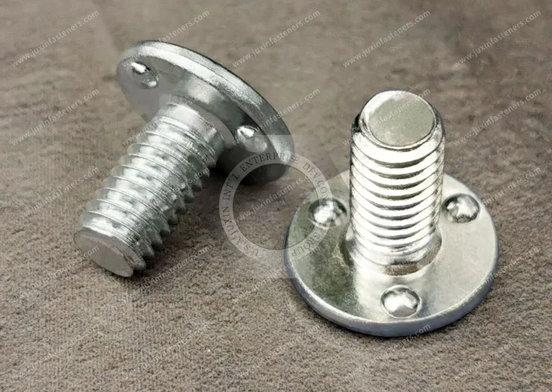
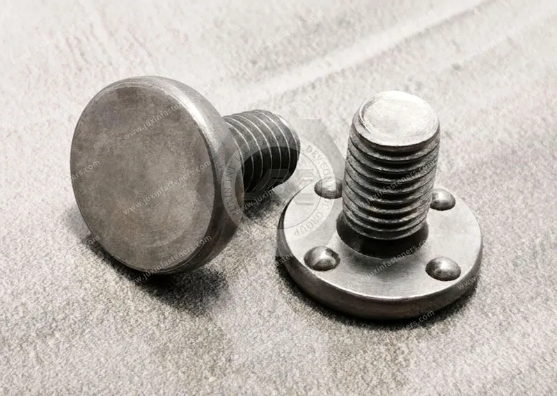
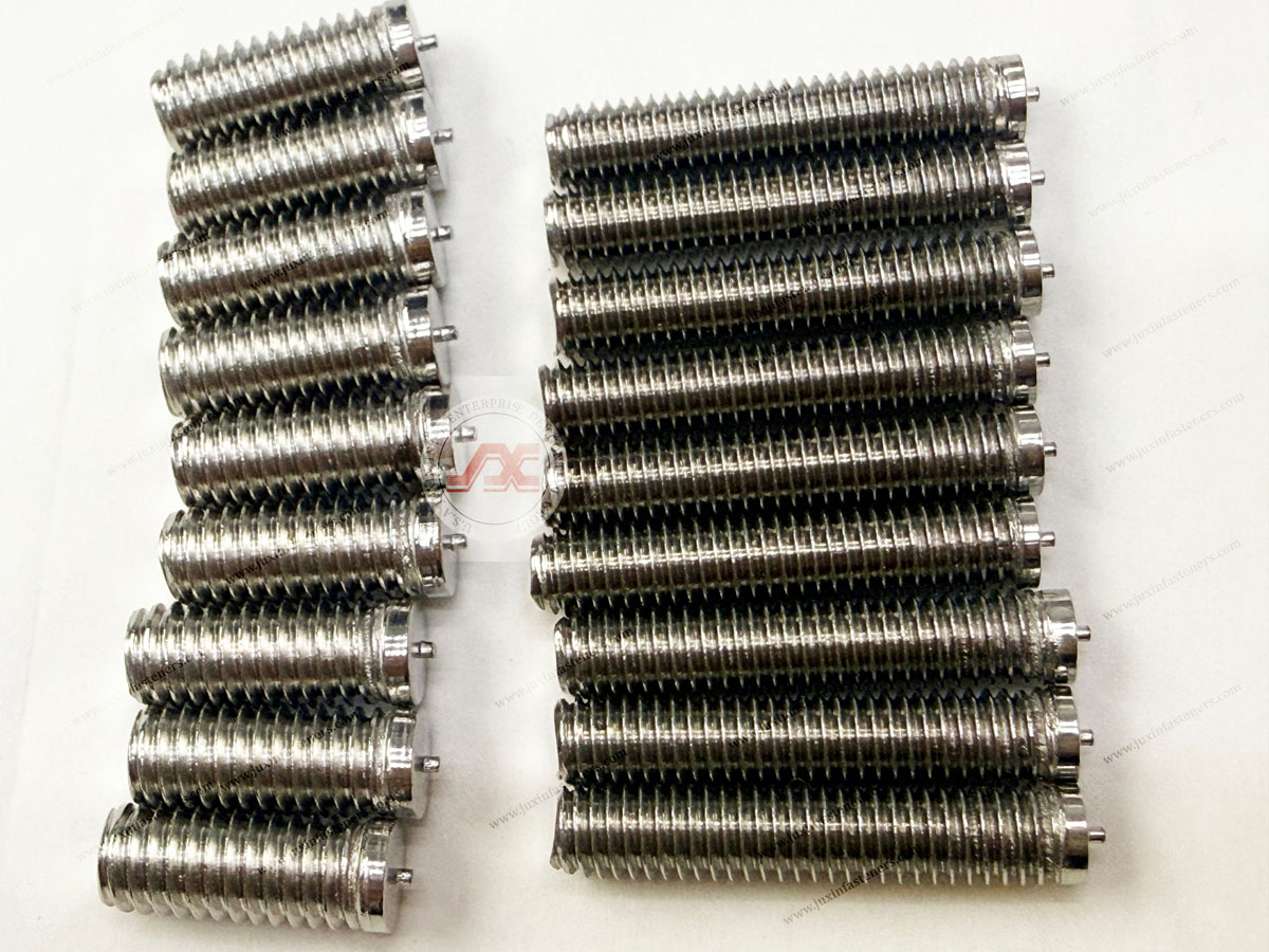
Product Category Page: JUXIN FASTENERS Projection Weld Studs
Commercial Sourcing Page: Contact JUXIN FASTENERS Engineering
A: Weld fasteners can be used with various metallic substrates, including many low-carbon steels, stainless steels, HSLA steels, and other weldable sheet materials. Compatibility depends on the specific fastener material, substrate grade, thickness, surface condition, projection geometry, welding equipment, and required joint performance.
A: Many low-carbon steel sheets are well suited to resistance welding, which is one reason they are widely used in weld-fastener applications.
However, the actual sheet grade, thickness, coating, surface condition, and welding schedule should still be validated for the intended production process.
A: Yes. Stainless steel substrates can be used with weld nuts and other weld fasteners when the fastener material and welding process are appropriately selected.
Stainless steel has different electrical and thermal characteristics from carbon steel, so welding conditions should be developed or validated specifically for the application.
A: Dissimilar carbon-steel-to-stainless-steel combinations can be possible in engineered applications, but they require additional evaluation.
Engineers should consider electrical and thermal differences, interface metallurgy, corrosion compatibility, coating requirements,
and the required mechanical performance rather than assuming that all dissimilar combinations are either acceptable or unacceptable.
A: Carbon equivalent can provide useful information about the composition and hardening tendency of certain steels,
but it should not be used as a universal pass/fail criterion for resistance weld-fastener applications.
The actual steel grade, thermal cycle, joint geometry, welding process, and required performance must also be considered.
A: It may. Changes in electrical resistivity, thermal conductivity, thickness, surface condition, and metallurgical behavior can alter the welding response.
Production parameters should therefore be validated whenever a material change could significantly affect the joint.
A: Yes. Coatings can change contact resistance, electrode behavior, expulsion characteristics, and electrode wear.
The specific coating system and production welding process should be evaluated together when selecting the weld fastener and welding schedule.
Selecting a weld fastener is not simply a matter of choosing a nut or stud made from the same nominal metal as the sheet.
The complete joint should be evaluated according to the substrate grade, sheet thickness, surface coating, fastener material, projection geometry,
welding process, corrosion environment, and required mechanical performance.
For OEM and industrial projects, send our engineering team:
Substrate material grade
Sheet thickness
Surface treatment or coating
Weld fastener drawing or specification
2D engineering drawings
CAD files where available
Welding process information
Required mechanical performance
Annual production quantity
EMAIL: info@juxinfasteners.com
JUXIN FASTENERS supports OEM customers with weld fastener material selection, DFM review, custom weld fastener development,
sample evaluation, production validation, and factory-direct supply for demanding industrial applications.
The objective is not simply to find a material that can be welded. It is to establish a stable material–fastener–process combination that can deliver repeatable joint performance throughout production.
Product Packaging
Packaging Standard
At Juxin Fasteners, we apply standardized export packaging to ensure product protection, traceability, and compliance with international logistics requirements.
1. Standard Export Packaging
Unless otherwise specified, all products will be packed according to our factory standard export packaging, which includes:
Moisture-resistant inner protection
Poly bag or small box packing as required
Reinforced export cartons
Clear labeling with part number, specification, batch number, and quantity
Palletizing for sea or air shipment when necessary
Our standard packaging is designed to ensure safe transportation, efficient warehousing, and long-distance international shipping.
2. Customized Packaging Options
We also provide customized packaging solutions according to customer requirements, including but not limited to:
Private labeling
Customized barcodes
Specific carton dimensions
Retail packaging
Special pallet configuration
Customer-specific marking and identification
So that you know, customized packaging may involve additional costs and extended lead time depending on the complexity of the requirements.
3. Compliance & Quality Assurance
All packaging processes are controlled under our ISO 9001 quality management system to ensure consistency, traceability, and product integrity throughout the supply chain.
Product Pictures
Contact Us
Tel.:
+86 020 8621 0320
+86 020 3121 6067
E-mail:
Technical Support:
Navigation
SEND INQUIREY