Call Us
+86 136 6007 9809
Call Us
+86 136 6007 9809

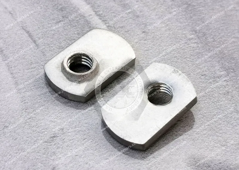
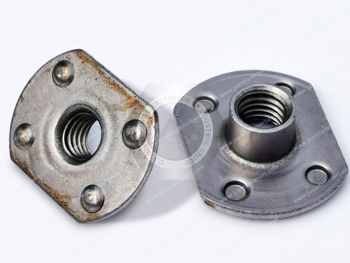
A right-angle weld nut is a specialized internally threaded fastener designed so that the threaded axis is positioned at an angle to the primary mounting surface,
commonly creating a perpendicular or approximately 90-degree fastening orientation.
Product Specification
A right-angle weld nut is a specialized internally threaded fastener designed so that the threaded axis is positioned at an angle to the primary mounting surface,
commonly creating a perpendicular or approximately 90-degree fastening orientation.
Instead of bending the parent sheet or adding a separate bracket and loose nut, the right-angle weld nut can create the required threaded mounting point as an integrated component.
             THREAD AXIS
             =========>

          +-------------+
          | THREADED    |
          | BODY        |
          +-------------+
                |
                |
          MOUNTING TAB
                |
                |
    ============+================
             SHEET METAL
The key engineering benefit is geometric integration.
Right-angle weld nuts can be useful when the assembly requires:
a thread facing into a narrow space
a perpendicular mounting point
a threaded connection near a corner
a compact alternative to a fabricated bracket
a fixed thread position in an enclosure or frame
JUXIN FASTENERS can manufacture custom right-angle weld nuts according to thread orientation, tab geometry, offset distance, material, and welding requirements.
A conventional flat weld nut works well when the threaded axis is normal to the sheet.
However, many real assemblies do not provide that geometry.
For example:
STANDARD WELD NUT

          BOLT
           ||
           ||
        +------+
        | NUT  |
        +------+
    ================= SHEET


RIGHT-ANGLE CONFIGURATION

              BOLT
       <============

          +------+
          | NUT  |
          +------+
              |
              |
    ==========+========== SHEET
The right-angle configuration can eliminate additional sheet-metal forming or a separate bracket.
That can reduce:
component count
assembly operations
loose hardware
bracket inventory
positional stack-up
However, the welded tab becomes part of the structural load path. The designer must therefore evaluate bending and peel forces rather than treating the fastener as simply a conventional nut rotated by 90 degrees.
This is one of the most important design considerations for right-angle weld nuts.
When the mating bolt is tightened or loaded, the force does not necessarily act directly through the center of the welded area.
The result can be a moment:
        LOAD
        <=====
           |
        +------+
        | NUT  |
        +------+
           |
           |  OFFSET
           |
      +----+----+
      | WELD TAB|
      +---------+
    ============= SHEET
The engineering evaluation should consider:
tensile force
shear force
bending moment
bolt installation torque
weld area
tab thickness
substrate thickness
fastener orientation
edge proximity
This is why a generic statement such as "two projections are always enough" is not an adequate engineering specification.
The projection layout must be matched to the actual load path.
| Criterion | Right-Angle Weld Nut | Bracket + Conventional Nut |
|---|---|---|
| Component count | Potentially lower | Higher |
| Thread position | Integrated into fastener geometry | Depends on bracket manufacturing |
| Assembly operations | Can be simplified | Additional fabrication/assembly may be required |
| Spatial efficiency | Often advantageous | Depends on bracket geometry |
| Tolerance stack-up | Can be reduced | Includes bracket and bend tolerances |
| Welding | Fastener-to-sheet welding | Bracket fabrication plus attachment |
| Customization | Thread and tab geometry can be customized | Bracket design provides broad flexibility |
| Load path | Must account for tab bending and weld loads | Depends on bracket stiffness and attachment |
The best solution depends on production volume and the required load path.
For high-volume OEM production, integrating the threaded feature directly into the welded component can be particularly attractive when it eliminates a secondary bracket operation.
The threaded axis must be controlled relative to the mounting surface.
Important characteristics may include:
angular orientation
thread-axis location
offset distance
thread height
mounting-tab dimensions
The appropriate tolerances should come from the assembly drawing and mating component requirements rather than from a universal angle value.
The welding projections should be positioned to support the actual load path.
For example:
             THREAD
               ||
               ||
          +---------+
          |   NUT   |
          +---------+
          | P1   P2 |
          +---------+
        =================
             SHEET
Multiple projections can help stabilize the fastener during welding and distribute the welded attachment.
However, increasing the number of projections does not automatically increase joint performance. Electrical current distribution, projection geometry, electrode force, substrate condition, and welding parameters all interact.
Right-angle weld nuts are often installed close to:
bends
flanges
corners
cutouts
structural members
The surrounding geometry must allow:
proper electrode access
fixture positioning
nut seating
bolt installation
tool clearance
post-weld inspection
A theoretically correct fastener can fail in production if the welding gun cannot reach the joint consistently.
Resistance welding performance depends on the complete electrical and mechanical circuit.
Important variables include:
fastener material
substrate material
surface condition
projection geometry
electrode material
electrode force
welding current
welding time
hold conditions
alignment
Right-angle geometry can make electrode access more complicated than with a flat weld nut.
Therefore, the welding cell should be considered during the DFM stage.
A sample trial should confirm:
stable positioning
acceptable weld formation
repeatable thread orientation
absence of damaging spatter
adequate weld strength for the intended application
Right-angle weld nuts can create mounting points for:
internal rails
brackets
covers
transformers
electrical components
cable-management structures
The main advantage is the ability to create the required thread orientation without adding another bracket.
Compact equipment frames often contain narrow channels and folded sheet-metal sections.
A right-angle weld nut can provide a fixed threaded location where conventional hardware would require additional structural components.

Potential applications include:
support brackets
cross-member attachments
interior structures
instrument-panel components
body structures
The fastener should be validated against the actual vibration, fatigue, corrosion, and assembly requirements of the vehicle program.
Material selection should consider both mechanical requirements and welding compatibility.
Factors include:
fastener alloy
parent-metal alloy
weldability
electrical resistance
corrosion environment
post-weld coating
service temperature
required mechanical properties
A corrosion-resistant material is not automatically the best choice for every resistance-welding application.
Likewise, a coating selected for corrosion protection may change the electrical characteristics of the welding interface.
The material and finish should therefore be evaluated together with the welding process.
A professional RFQ should contain enough information for the supplier to understand the complete application.
2D drawing
3D CAD model
thread specification
tab geometry
required thread orientation
substrate material
substrate thickness
welding process
surface treatment
annual volume
inspection requirements
packaging requirements
Can the supplier control thread-axis orientation?
This is particularly important when the mating component has a fixed hole pattern.
Can the supplier customize the offset?
Custom offset geometry can solve spatial conflicts that cannot be addressed with standard catalog parts.
Can the supplier evaluate welding access?
A drawing review should consider the welding gun and electrode geometry, not just the fastener itself.
Can the supplier support production validation?
For OEM applications, sample welding and dimensional validation are valuable before production tooling is released.
Potential inspection characteristics include:
thread gauge
thread position
angular orientation
tab dimensions
projection geometry
material
surface finish
weld-face condition
overall dimensions
For critical assemblies, dimensional inspection should be combined with functional testing using the actual mating component.
Weld performance should also be validated according to the customer's engineering specification and production process.
It provides an integrated threaded mounting point with a non-standard thread orientation, allowing designers to solve spatial constraints without necessarily adding a separate sheet-metal bracket.
They can be, but the answer depends on the complete joint design. The weld attachment, tab geometry, substrate, load direction, and installation torque all need to be evaluated.
Yes. JUXIN FASTENERS can evaluate custom thread orientation, offset distance, tab geometry, thread dimensions, welding projections, materials, and finishes based on OEM drawings.
No. The fixture remains important for controlling fastener location and orientation during production welding.
For custom right-angle weld nuts, send JUXIN FASTENERS:
2D engineering drawing
3D CAD model
thread specification
required thread orientation
offset dimensions
substrate material and thickness
welding method
annual quantity
surface-treatment requirements
Email: info@juxinfasteners.com
JUXIN FASTENERS can review the complete assembly geometry and recommend a weld-nut configuration that balances thread position, welding access, manufacturability, and OEM production requirements.
Product Packaging
Packaging Standard
At Juxin Fasteners, we apply standardized export packaging to ensure product protection, traceability, and compliance with international logistics requirements.
1. Standard Export Packaging
Unless otherwise specified, all products will be packed according to our factory standard export packaging, which includes:
Moisture-resistant inner protection
Poly bag or small box packing as required
Reinforced export cartons
Clear labeling with part number, specification, batch number, and quantity
Palletizing for sea or air shipment when necessary
Our standard packaging is designed to ensure safe transportation, efficient warehousing, and long-distance international shipping.
2. Customized Packaging Options
We also provide customized packaging solutions according to customer requirements, including but not limited to:
Private labeling
Customized barcodes
Specific carton dimensions
Retail packaging
Special pallet configuration
Customer-specific marking and identification
So that you know, customized packaging may involve additional costs and extended lead time depending on the complexity of the requirements.
3. Compliance & Quality Assurance
All packaging processes are controlled under our ISO 9001 quality management system to ensure consistency, traceability, and product integrity throughout the supply chain.
Product Pictures
Hot Products
Contact Us
Tel.:
+86 020 8621 0320
+86 020 3121 6067
E-mail:
Technical Support:
Navigation
SEND INQUIREY