
Call Us
+86 136 6007 9809
Call Us
+86 136 6007 9809

Sep. 25, 2026
A custom fastener can match the engineering drawing and still create problems when it reaches production.
A self-clinching nut may meet its external dimensions but perform differently after installation in the customer's panel.
A captive screw may pass dimensional inspection but fail to retract far enough for service access.
A custom stud may fit correctly but use the wrong material condition or surface finish.
A component may function during manual assembly yet create feeding or installation problems when introduced into an automated production line.
For this reason, prototype and pre-production approval should not be reduced to a simple question:
“Does the sample look correct?”
Fastener sample validation should establish whether the supplied component meets the defined requirements for:
drawing conformity
dimensional accuracy
thread compatibility
material
heat treatment
hardness
surface finish
corrosion performance
mechanical performance
installation
assembly fit
production-process compatibility
quality documentation
Also searched as prototype fastener testing, fastener FAI inspection, PPAP fasteners, pre-production fastener validation,
fastener sample approval, custom fastener quality inspection, and supplier fastener qualification, this process creates the technical bridge between development and repeat production.
A practical validation path is:
Engineering requirement → sample plan → dimensional verification → material and finish verification
→ functional testing → assembly trial → documentation review → customer approval → production release
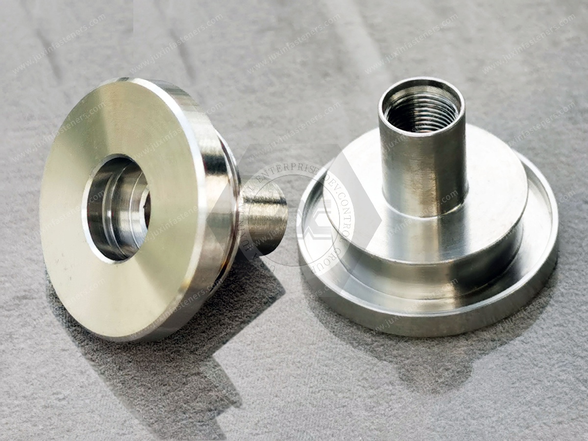
Sample validation reduces the risk of discovering technical problems after production quantities have already been manufactured or introduced to the assembly line.
Potential issues include:
incorrect thread
dimensional variation
insufficient shoulder clearance
improper seating
unsuitable installation force
inadequate panel retention
coating interference
plating damage
material mismatch
hardness outside specification
automated feeding problems
tool-access interference
The validation plan should be proportional to the risk of the component and application.
A standard commercial screw does not necessarily require the same qualification program as a custom automotive stud or an engineered captive panel fastener.
“Sample approved” can mean very different things to different organizations.
For one project, approval may mean:
Dimensions checked → assembly fit confirmed
For another, it may require:
Drawing review → full dimensional layout → material verification → coating verification → mechanical testing → production-line trial → customer documentation approval
The first step in a serious sample program is therefore to define:
What does approval mean for this specific part?
A useful validation framework contains six major areas.
Confirm that the component meets the controlled engineering drawing and applicable tolerances.
Confirm specified material, hardness, heat treatment, or mechanical-property requirements where applicable.
Confirm the specified coating, plating, passivation, coating thickness, or corrosion requirement.
Verify relevant component or installed-joint performance.
Confirm that the component works correctly in the intended panel, mating component, assembly process, and tooling.
Review the required FAI, material documentation, customer-specific PPAP elements, inspection records, and production controls.
Not every project requires every test.
The validation plan should be defined by the drawing, application risk, customer requirements, and applicable standards.
Before inspecting a sample, confirm what specification controls it.
The validation package may reference:
customer 2D drawing
drawing revision
customer specification
supplier drawing
material specification
surface-finish specification
applicable ISO, DIN, EN, ASTM, SAE, ASME/ANSI, BS, or other recognized standard
approved functional-equivalent specification
Testing without a controlled requirement can produce data without a clear acceptance criterion.
Always confirm the drawing revision used to manufacture and inspect the samples.
This becomes especially important when:
the design changed after quotation
prototypes were made from an earlier revision
tooling was started before final drawing release
the customer changed a tolerance
material or finish changed during development
The sample report should clearly identify the drawing or specification revision against which the part was evaluated.
Not every dimension has the same effect on the application.
Critical-to-Quality characteristics, or CTQs, can include features that directly influence:
fit
function
assembly
load transfer
retention
alignment
sealing
electrical contact
serviceability
Examples may include:
shoulder diameter
shoulder length
mounting interface
thread
head height
installed height
under-head geometry
locating diameter
captive travel
standoff height
The CTQ list should come from the actual application and customer quality requirements.

A first-article dimensional layout may inspect all drawing characteristics.
Production control does not necessarily require every characteristic to receive the same inspection frequency forever.
After approval, characteristics may be controlled through different methods based on:
functional risk
manufacturing process
process capability
tooling control
measurement system
customer requirement
This distinction helps avoid both under-inspection of critical features and unnecessary inspection of stable non-critical features.
Depending on component geometry and tolerance, inspection equipment may include:
digital calipers
micrometers
height gauges
thread gauges
optical comparators
vision measurement systems
CMM equipment
surface roughness measurement equipment
dedicated functional gauges
The correct method depends on the characteristic being measured.
Optical systems can be useful for fastener features such as:
profile
radii
chamfers
undercuts
head geometry
thread profile
stepped geometry
However, no single measurement technology is automatically appropriate for every characteristic.
CMM inspection can be useful for complex dimensional relationships and geometric characteristics where appropriate.
But using a CMM does not automatically make an inspection more accurate.
Measurement uncertainty, fixturing, datum definition, feature accessibility, part geometry, and measurement strategy still matter.
Thread inspection may involve:
GO/NO-GO gauges
thread ring gauges
thread plug gauges
pitch measurement
dimensional thread measurement
functional mating checks
The drawing should identify the applicable thread requirement.
Common industrial systems include ISO metric threads and Unified inch threads used in ASME/ANSI-based assemblies.
A thread that meets requirements before coating may behave differently after plating or coating.
Relevant factors can include:
coating thickness
thread allowance
coating buildup
post-treatment
friction
Final thread inspection should therefore reflect the supplied finished condition where required.
Material documentation can be important for custom and safety-relevant fasteners.
Depending on the project, documentation may include:
material certificate
mill certificate
Material Test Report
EN 10204 3.1 inspection certificate where specified
chemical composition
mechanical-property data
The required certificate type should be defined during RFQ review.
A raw-material certificate confirms information about the supplied material batch.
It does not automatically confirm:
finished-part dimensions
heat-treatment result
final hardness
thread quality
coating
installed performance
Material documentation is one part of the validation package, not a substitute for finished-part inspection.
Where hardness or heat treatment is specified, verification may include appropriate testing of the finished component or representative process samples.
Requirements can involve:
core hardness
surface hardness
case depth where applicable
strength class
mechanical properties
The correct test method and location depend on:
material
geometry
heat-treatment process
applicable specification
Different self-clinching and panel-fastener designs can use different materials and manufacturing routes.
The required relationship between fastener hardness and host panel characteristics depends on the specific product architecture.
Therefore, hardness requirements should come from:
drawing
validated design
product specification
application requirements
rather than a generic assumption.
Surface finish inspection may evaluate:
coating type
coating thickness
appearance
coverage
adhesion where applicable
corrosion requirement
friction requirement where specified
Possible systems can include:
zinc-based coatings
zinc-nickel
zinc flake
nickel-based finishes
passivation
anodizing for appropriate aluminum components
customer-defined finishes
The finish must be evaluated against the actual specification.
Coating thickness may be measured using methods appropriate to:
substrate
coating system
geometry
required accuracy
Possible techniques include XRF or other suitable measurement methods.
Do not apply one universal coating thickness to all fastener finishes.
Where specified, corrosion testing may reference methods such as:
ASTM B117
ISO 9227
The standard defines a test method.
It does not automatically define how many hours a specific fastener must survive.
The required exposure duration and acceptance criteria should come from:
customer drawing
coating specification
OEM requirement
applicable program specification
Simply writing “ASTM B117” on an RFQ does not fully define corrosion performance.
A useful requirement should identify, where applicable:
coating system
test method
exposure duration
white-corrosion criterion
red-rust criterion
evaluation location
any customer-specific acceptance requirement
This avoids disagreements after testing.
High-strength steel fasteners processed through certain electroplating or chemical-treatment routes can require hydrogen-embrittlement risk controls.
The correct control strategy depends on:
material strength
hardness
manufacturing process
cleaning process
coating process
applicable standard
customer requirement
Possible controls may include process management, baking requirements, testing, or other specification-defined measures.
No single baking cycle or sustained-load test should be applied universally to every plated steel fastener.
Mechanical validation should match the fastener's function.
Possible tests include:
tensile testing
proof-load testing
hardness testing
wedge testing where applicable
torsional testing
push-out testing
torque-out testing
clamp-load evaluation
installation-force measurement
Not every test applies to every component.
Push-out testing is particularly relevant to certain self-clinching, press-in, or permanently installed panel fasteners.
The test evaluates axial retention after installation into a representative host panel.
Results depend on:
fastener geometry
panel material
panel hardness
panel thickness
mounting-hole condition
installation force
tooling
Therefore, push-out values should always be interpreted together with the test-panel conditions.
Torque-out testing evaluates resistance to rotation of the installed component within the host material.
It can be relevant to:
self-clinching nuts
studs
standoffs
other permanently installed threaded components
The acceptance requirement should be defined by the customer, drawing, validated baseline, or application requirement.
A supplier should not treat a push-out or torque-out value as a universal property of the fastener alone.
The installed system includes:
Fastener + mounting hole + host material + host hardness + panel thickness + installation tooling + installation force
Changing one of these variables can change the result.
For supplier qualification, testing should therefore reproduce representative production conditions.
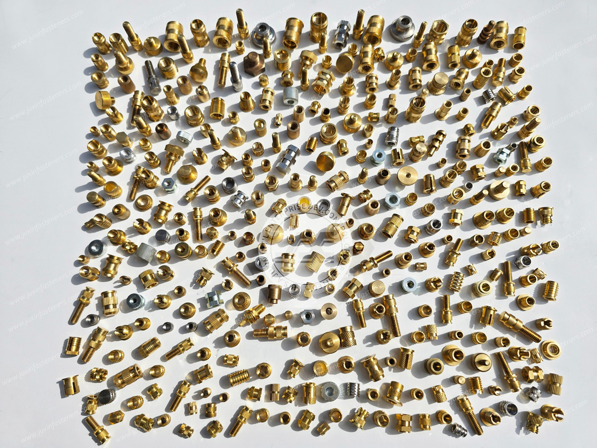
For press-installed hardware, validation may include installation-force evaluation.
Too much force can:
distort the panel
damage cosmetic surfaces
increase tooling load
deform nearby features
Too little force can result in:
incomplete seating
inadequate material flow
poor retention
Installation-force requirements should be established for the specific fastener and host material.
Where flush seating is required, samples should be inspected after installation.
A fastener can meet its free-state dimensions but still seat incorrectly because of:
hole condition
panel hardness
installation force
tooling geometry
fastener geometry
Installed-state validation can therefore be more informative than measuring the loose component alone.
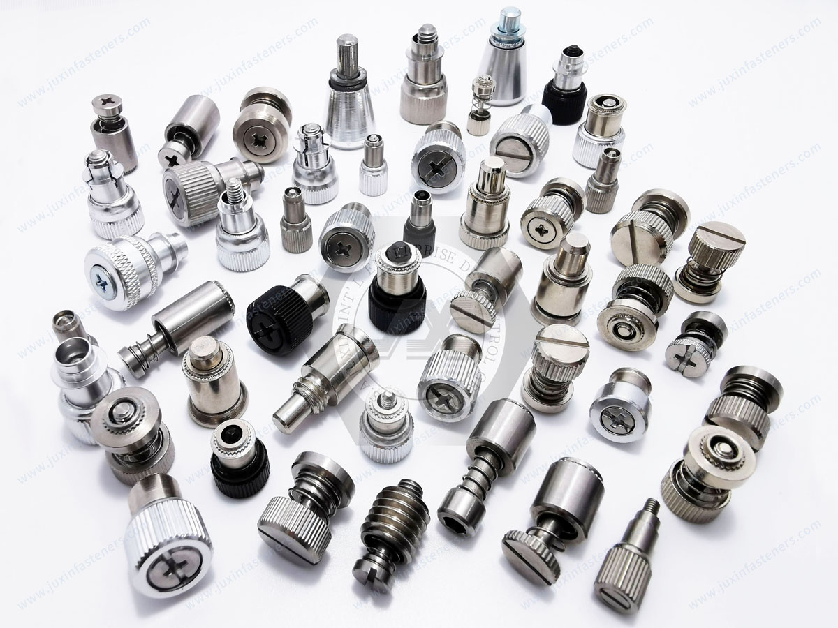
Captive hardware requires additional functional checks.
Depending on design, validation may include:
mounting retention
extended position
retracted position
screw travel
spring function
thread engagement
head clearance
service access
A captive screw that passes dimensional inspection can still fail the actual serviceability requirement.
Floating nuts and related components may require validation of:
lateral movement
thread position
anti-rotation
panel retention
installation
assembly alignment
Too little float may prevent assembly.
Excessive uncontrolled movement may create other assembly issues.
The correct range depends on the tolerance stack of the actual system.
For standoffs, important characteristics can include:
installed height
thread
perpendicularity
panel retention
push-out resistance
torque-out resistance
PCB or component clearance
Installed height can be particularly important in electronics packaging.
A major qualification question is:
Were the samples produced using the intended production process?
Prototype parts may sometimes be manufactured by a temporary process to accelerate engineering development.
For example:
CNC-machined prototype
production part planned for cold forming plus secondary machining
The prototype may validate geometry and assembly fit, but it may not fully validate the future production process.
This distinction is critical.
A prototype can confirm:
geometry
interface
basic assembly
design concept
Production-intent samples can additionally validate:
tooling
manufacturing sequence
production material
heat treatment
thread process
final coating
process variation
For higher-risk or high-volume programs, both gates may be appropriate.
First Article Inspection, commonly called FAI, provides documented evidence that an initial production or pre-production part conforms to the defined engineering requirements.
The exact FAI format depends on:
customer requirements
industry
drawing
quality agreement
A typical FAI may include:
drawing characteristic identification
measured results
specification references
material documentation
finish documentation
inspection equipment references
sample identification
Where required, the engineering drawing can be ballooned so each characteristic corresponds to an inspection result.
The report may record:
nominal dimension
tolerance
measured value
pass/fail status
inspection method
The number of parts measured should be defined by the customer's quality requirement or agreed validation plan.
There is no universal sample quantity that applies to every FAI.
Production Part Approval Process, or PPAP, is widely associated with automotive supply chains and may also be requested by customers in other sectors.
However, PPAP is not automatically required for every fastener or every industry.
The customer should specify:
whether PPAP is required
submission level
applicable customer-specific requirements
required elements
timing
Where a customer specifically requests PPAP Level 3, the submission package can include applicable elements such as:
design records
authorized engineering-change documents where applicable
customer engineering approval where required
Design FMEA where supplier design responsibility applies
process flow diagram
Process FMEA
control plan
measurement system analysis
dimensional results
material and performance test results
initial process studies
qualified laboratory documentation where applicable
appearance approval where applicable
sample production parts
master sample where required
checking aids where applicable
customer-specific requirements
Part Submission Warrant
The exact package should follow the customer's applicable PPAP requirements rather than a simplified universal checklist.
PPAP organizes evidence that the manufacturing process can produce a conforming part.
It does not replace the engineering specification.
For example, PPAP itself does not independently decide:
required push-out force
required torque-out resistance
required salt-spray duration
thread class
coating thickness
Those requirements must come from the drawing, customer specification, approved design, or applicable technical standard.
For selected characteristics, customers may request process-capability analysis.
Cpk evaluates how a stable process is performing relative to specification limits.
But Cpk should not be treated as a universal fixed acceptance number for all fasteners.
The required capability threshold can depend on:
customer-specific requirements
launch phase
characteristic classification
safety significance
process maturity
quality agreement
The correct requirement should be confirmed before production approval.
A Cpk calculation is only useful when the underlying measurement data is reliable.
Before relying on capability results, quality teams may need to consider:
measurement resolution
repeatability
reproducibility
operator influence
fixture influence
calibration
This is why measurement-system analysis can be important for critical characteristics.
A process can be statistically stable and capable while consistently producing the wrong engineering requirement if:
the wrong drawing revision is used
the measurement method is inappropriate
the specification was entered incorrectly
the CTQ was misunderstood
Quality approval therefore begins with requirement control before statistical analysis.
Samples should be evaluated in the actual assembly whenever practical.
This can reveal problems that loose-part inspection cannot detect.
Examples include:
insufficient clearance
thread mismatch
incorrect grip
interference
poor seating
inadequate float
captive travel problems
tool-access issues
Assembly validation is particularly valuable for custom and functional-equivalent hardware.
For high-volume OEM programs, the sample should sometimes be evaluated not only in the final product but also in the manufacturing process.
Questions include:
Does it feed correctly?
Does it orient correctly?
Can existing tooling install it?
Does installation force remain within the approved process window?
Does it affect cycle time?
Does it create abnormal tool wear?
Can automated inspection recognize it?
This can be essential for automotive, electronics, server, and automated sheet-metal production.
A component can be dimensionally conforming and function correctly after manual installation while still being unsuitable for production automation.
Therefore, for high-volume programs:
Part conformity + assembly function + manufacturing compatibility
may all be required before approval.
Automated optical inspection can be valuable for suitable fastener characteristics.
Potential checks can include:
presence of features
overall length
head geometry
thread presence
gross dimensional defects
mixed parts
However, optical sorting does not guarantee zero defects.
Detection capability depends on:
camera resolution
lighting
orientation
algorithm
characteristic
defect type
validated inspection limits
Optical sorting should therefore be treated as one control method within the overall quality plan.
Many OEM supply chains pursue very low defect rates and strong defect-prevention systems.
But quality communication should distinguish between:
quality objective
process controls
inspection strategy
absolute guarantee
A supplier should avoid claiming that inspection alone guarantees zero defects.
Prevention, process control, measurement, traceability, inspection, corrective action, and continuous improvement work together.
High-density AI computing equipment creates demanding mechanical packaging requirements.
Potential fastener applications include:
GPU server chassis
compute trays
power shelves
liquid-cooling equipment
network systems
storage systems
Components can include:
captive panel screws
self-clinching nuts
studs
standoffs
custom threaded components
Validation may focus on:
envelope
head height
installed height
captive retraction
thread engagement
automated assembly compatibility
In a dense server chassis, even a small dimensional difference can affect:
rail clearance
PCB clearance
service access
faceplate alignment
airflow-related packaging
The relevant CTQs should therefore be derived from the actual chassis architecture.
Cooling distribution units, pumps, manifolds, heat exchangers, and associated hardware can introduce additional requirements involving:
corrosion
vibration
temperature
sealing interfaces
If a fastener directly influences a sealed or pressure-containing interface, system-level validation may be required.
A fastener sample alone cannot establish the complete sealing performance of the assembly.
Automotive and EV programs can require structured supplier qualification and customer-specific production approval.
Applications may include:
battery systems
BMS enclosures
high-voltage junction boxes
traction inverters
electronic control modules
thermal-management assemblies
structural brackets
Depending on the program, validation can include:
dimensional inspection
material verification
coating verification
mechanical testing
production-intent samples
PPAP
customer-specific requirements
Do not assume the same PPAP package or test limits apply to every automotive component.
EV battery hardware can experience combinations of:
vibration
thermal cycling
corrosion exposure
dissimilar materials
electrical requirements
Relevant validation can include:
panel compatibility
installed retention
coating performance
material documentation
electrical function where applicable
assembly trials
Requirements should be established by the specific battery or vehicle program.
Power equipment can use fasteners in:
switchgear
inverters
UPS systems
busbar assemblies
power distribution equipment
control cabinets
Validation may need to consider:
mechanical retention
electrical bonding
grounding
clearance
corrosion
serviceability
If the fastener performs an electrical function, mechanical inspection alone is insufficient.
BESS hardware can be used in:
battery modules
enclosures
inverter systems
power conversion equipment
thermal-management systems
Outdoor applications may require defined environmental and corrosion performance.
Qualification should reflect the actual installed environment.
Telecommunications infrastructure can require sample validation for:
outdoor cabinets
radio units
network equipment
power enclosures
Important characteristics can include:
corrosion
captive retention
grounding
sealing-related clamp function
long-term serviceability
Semiconductor equipment can require precise custom fasteners and threaded components.
Depending on the system, qualification may involve:
dimensional precision
material control
surface requirements
cleanliness
traceability
Do not assume a generic fastener validation package satisfies semiconductor-equipment requirements without customer review.
Automated equipment can use:
shoulder fasteners
locating studs
panel hardware
custom screws
standoffs
Moving mechanisms may require additional evaluation of:
fit
hardness
wear
alignment
surface finish
Medical diagnostic and laboratory equipment can require controlled hardware qualification.
Requirements may include:
dimensional documentation
material traceability
corrosion
cleanliness
customer-specific quality records
Medical compliance should never be inferred merely because a fastener passes dimensional inspection.
Rail systems often involve long product lifecycles and controlled supplier qualification.
Fastener validation can support:
new production
refurbishment
second-source qualification
replacement hardware
Program requirements may include:
material documentation
inspection reports
mechanical testing
corrosion requirements
change control
Aerospace-related hardware can be subject to highly specific drawing, material, process, inspection, traceability, and approval requirements.
Where aerospace standards or customer specifications apply, they should control the validation plan.
A general FAI or commercial sample approval should not be represented as equivalent to aerospace customer approval.
Sample validation is especially important when qualifying a second supplier.
The comparison may involve:
original approved component
customer drawing
functional requirements
proposed alternative
The objective is not necessarily to make every measured property identical to the original supplier.
The objective is to demonstrate compliance with the customer's approved requirements.
For functional-equivalent hardware, validation may include:
form
fit
function
mounting-hole compatibility
panel-thickness compatibility
installation
tooling compatibility
mechanical retention
finish
assembly-line behavior
This connects functional-equivalent sourcing directly with sample qualification.
For drawing-based custom components, the sample-validation process begins with the controlled customer print.
The path becomes:
2D drawing → DFM → sample manufacturing → FAI → application validation → production approval
Where required, customer-specific PPAP or other quality documentation can be integrated into this process.
When the project begins from an existing physical component rather than a drawing, the replacement specification should first be established.
The path becomes:
Physical sample → dimensional and functional review → replacement drawing → sample production → validation → customer approval
Do not use validation testing to disguise unresolved assumptions about the original component.
For fastener sample validation, prototype fastener testing, FAI fastener inspection, PPAP fasteners, pre-production fastener validation,
custom fastener sample approval, or second-source fastener qualification, provide as much of the following information as possible:
controlled 2D engineering drawing
drawing number
drawing revision
3D STEP model where available
applicable technical specifications
material specification
heat-treatment requirement
hardness requirement
thread specification
thread tolerance or class
CTQ characteristics
surface finish
coating specification
coating thickness requirement where applicable
corrosion test method
corrosion acceptance requirement
host panel material
panel hardness where relevant
panel thickness
mounting-hole specification
installation method
installation tooling information
installation force requirement where applicable
push-out requirement where applicable
torque-out requirement where applicable
tensile or proof requirement where applicable
vibration requirement where applicable
electrical requirement where applicable
sample quantity
required FAI documentation
material-certificate requirement
PPAP requirement and submission level where applicable
customer-specific quality requirements
Estimated Annual Usage
pilot-production schedule
production launch schedule
packaging requirements
If a requirement is not known, identify it as open rather than creating an arbitrary acceptance value.
Useful questions include:
Which drawing revision was used?
Were these samples made with production-intent material?
Were they manufactured with production tooling?
Will the production manufacturing route be the same?
Which characteristics are CTQs?
What inspection method was used for each CTQ?
Are thread gauges calibrated and appropriate?
What material documentation is available?
Was heat treatment performed on the sample lot?
What hardness was verified?
What coating system was applied?
Was coating thickness measured?
What corrosion requirement applies?
Were push-out or torque-out tests performed in representative panels?
What panel material, hardness, and thickness were used?
What installation force and tooling were used?
Were samples tested in the actual assembly?
Were they evaluated on the production line?
Is FAI required?
Is PPAP required?
Which PPAP level is required?
Are customer-specific requirements applicable?
Is process-capability evidence required?
What changes require customer notification after approval?
These questions connect engineering validation with supplier qualification.
Identify the correct drawing, revision, specifications, and customer requirements.
Determine which dimensions, materials, finishes, mechanical characteristics, and assembly functions require verification.
Clarify whether the sample is:
concept prototype
engineering prototype
production-intent sample
first article
PPAP sample
Verify drawing characteristics using suitable calibrated measurement methods.
Review applicable material, heat-treatment, hardness, and finish requirements.
Perform only the tests relevant to the component and application.
Install the samples into representative or actual customer assemblies.
Evaluate feeding, tooling, installation, and cycle compatibility.
Complete the required FAI, material documentation, test records, PPAP elements, or customer-specific forms.
Release the component according to the customer's engineering and quality process.
After approval, changes to critical materials, tooling, processes, finishes, or dimensions should be managed according to agreed customer requirements.
A successful sample program should create more than an approved physical part.
It should establish a controlled production baseline.
The complete path is:
Engineering requirement → DFM → sample → inspection → testing → assembly validation → documentation → customer approval → controlled production → ongoing quality management
This gives engineering confidence that the component performs as intended.
It gives SQEs traceable evidence for supplier approval.
And it gives procurement a stronger basis for releasing production orders and qualifying long-term supply.
JUXIN FASTENERS supplies standard and custom fasteners, self-clinching hardware, captive panel screws, nuts, studs, standoffs,
threaded inserts, cold-formed components, precision CNC machined parts, and drawing-based components for industrial OEM applications.
For projects involving fastener sample validation, prototype fastener testing, first-article inspection,
customer-specific PPAP requirements, functional-equivalent fasteners, second-source qualification,
or custom fastener production approval, our team can review the customer's drawing and quality requirements and coordinate the appropriate sample and documentation path.
A validation project can begin from:
customer 2D drawing
3D model
physical sample
functional-equivalent requirement
second-source project
customer quality specification
production application information
Depending on the project requirements, the validation path may include:
dimensional inspection
thread verification
material-document review
hardness verification
coating-thickness verification
corrosion testing requirements
push-out or torque-out testing
assembly fit-check
production-intent sample evaluation
FAI documentation
customer-specified PPAP documentation
The exact inspection and documentation package should be defined according to the customer's application, drawing, applicable standards,
and quality requirements rather than assumed from the fastener category alone.
For prototype samples, pre-production samples, FAI requirements, customer-specific PPAP projects, functional-equivalent qualification,
second-source validation, or production-volume RFQs, send your technical and quality requirements to JUXIN FASTENERS.
Email: info@juxinfasteners.com
Website: www.juxinfasteners.com
 MORE NEWS

Sep. 25, 2026

Sep. 25, 2026

Sep. 25, 2026
Contact Us
Tel.:
+86 020 8621 0320
+86 020 3121 6067
E-mail:
Technical Support:
Navigation
SEND INQUIREY