
Call Us
+86 136 6007 9809
Call Us
+86 136 6007 9809

Sep. 22, 2026
Standard U-nuts, J-nuts, clip-on nuts, and barrel clip nuts are efficient solutions for many sheet-metal assemblies.
They provide a removable threaded attachment point without welding, riveting, or permanent installation equipment.
However, catalog fasteners cannot solve every assembly problem.
Advanced automotive systems, EV electronics, industrial machinery, electrical enclosures, robotics equipment, rail systems, telecommunications hardware,
and specialized chassis may include flange geometries, hole locations, installation paths, or load conditions that fall outside standard clip dimensions.
A standard product may fail because it is:
Too wide for the available installation envelope
Too tall beneath a cover or electronic module
Too short to reach the pre-punched hole
Too deep for a narrow flange
Unable to fit the actual panel-thickness range
Misaligned with the mating screw
Difficult to install from the available direction
Unable to provide sufficient pre-assembly retention
Too stiff for manual installation
Too weak for automated handling
Incompatible with the specified coating or environment
Unsuitable for the required service-removal cycle
Custom clip-on nut design engineering addresses these constraints by developing the fastener around the real panel, screw, assembly sequence, operating environment, and production volume.
The objective is not simply to change the outline of an existing clip.
A successful custom spring fastener must achieve a controlled balance between fit, installation force, retention, elastic recovery,
thread engagement, torque capacity, corrosion protection, manufacturability, inspection, and commercial feasibility.
A custom clip-on nut is justified when a standard product cannot meet the functional requirements without forcing major changes to the customer’s sheet-metal assembly.
The development process normally includes:
Application and boundary-condition review
Standard-product gap analysis
Functional requirement definition
Material and coating selection
Initial geometry development
Dimensional and tolerance review
Optional simulation for high-risk geometry
Prototype or representative sample production
Fit, retention, torque, and durability testing
Customer design approval
Production-tooling development
Pilot production and capability verification
Controlled production release
The most important inputs are the actual panel geometry, panel thickness, hole location, bend radius, mating screw, installation method,
required retention, target torque, operating environment, validation criteria, and projected annual volume.
Custom development should solve a defined technical or commercial problem. It should not be initiated merely because a catalog part looks slightly different from the preferred concept.
A custom design may be appropriate under the following conditions.
The center of the panel clearance hole may sit farther from or closer to the edge than a standard clip throat can accommodate.
A custom throat depth can align the threaded feature with the existing hole while preserving sufficient panel-edge material and correct clip seating.
The surrounding assembly may limit fastener width, height, length, or insertion direction.
This is common near:
Printed circuit boards
Busbars
Sensors
Harness routes
Sealing flanges
Hinges
Reinforcement ribs
Molded plastic components
Battery and power-electronics modules
The sheet-metal edge may include:
A return flange
Hemmed material
A curved edge
A tapered flange
Multiple material layers
A formed bead
A local embossment
An angled installation surface
A non-perpendicular bend
A standard clip designed for a straight, single-layer flange may not seat correctly.
The application may use multiple sheet thicknesses or include a coating that changes the effective grip range.
The custom clip must provide reliable retention across the complete minimum-to-maximum panel stack without permanent spring deformation.
Manual assembly may require a lower push-on force, while automated production may require a tightly controlled installation-force window that prevents jams and confirms correct seating.
The clip may need to remain attached during shipping, robotic handling, panel inversion, powered screw rundown, or vibration before final tightening.
A centered U-nut may not work where the threaded position must be offset because of an adjacent component or asymmetric flange.
A custom profile may need to accommodate an ISO metric thread or an ASME unified-inch thread while maintaining sufficient thread engagement and torque performance.
Maintenance doors, filters, machine covers, and electronic access panels may require repeated screw removal without clip migration, thread damage, or loss of retention.
High humidity, road splash, salt-containing environments, cleaning chemicals, elevated temperature, or outdoor exposure may require a specific material and coating system.
Before creating a custom part, engineers should document why existing fasteners are unsuitable.
A standard-product gap analysis should compare:
| Design requirement | Standard fastener capability | Identified gap | Required custom action |
|---|---|---|---|
| Panel thickness | Available grip range | Clip is loose or too tight | Adjust spring-leg spacing |
| Hole setback | Standard throat depth | Thread does not align | Modify throat depth |
| Available height | Standard overall height | Interferes with adjacent part | Develop low-profile geometry |
| Retention force | Standard retention | Clip moves during handling | Tune spring contact features |
| Installation force | Standard push-on force | Excessive operator effort | Modify entry geometry |
| Thread position | Centered or fixed | Application requires offset | Develop offset thread feature |
| Coating | Standard zinc system | Environment requires more resistance | Review alternative finish or stainless material |
| Service cycles | General assembly | Repeated access required | Validate wear and thread durability |
This analysis prevents unnecessary tooling and gives procurement teams a defensible commercial reason for approving a custom component.
The customer drawing should not begin with the external shape of the spring fastener. It should begin with what the assembly must accomplish.
Critical functional requirements include:
Panel material
Minimum and maximum panel thickness
Coating condition
Edge geometry
Flange width
Bend radius
Hole diameter
Hole setback
Hole-position tolerance
Mating screw size
Thread pitch or series
Screw property class or grade
Installation direction
Driver-access direction
Required installation force
Minimum clip retention
Target tightening torque
Minimum strip or failure torque
Applied tensile and shear loads
Vibration profile
Temperature range
Corrosion environment
Required service-removal cycles
Available dimensional envelope
Prototype quantity
Projected annual volume
Without these inputs, the supplier can produce a component that matches the visible geometry but fails to meet the intended function.
The engineering team evaluates the complete assembly instead of reviewing the spring clip as an isolated part.
The analysis should answer:
What is the clip retaining before the screw is installed?
Which surface locates the clip?
What stops the clip at the correct seating depth?
How is the screw aligned with the thread?
Which direction does the installation load act?
Does the clip experience continuous spring deflection?
Can the operator or robot access the installation path?
Will the panel be coated before installation?
Must the fastener be removable?
What happens if the clip is installed incorrectly?
Photographs are useful, but section views, 3D models, and dimensioned panel drawings provide much stronger engineering information.
The fastener geometry must be designed around functional datums.
Typical datums include:
Panel free edge
Primary panel surface
Clearance-hole centerline
Formed flange surface
Bend tangent
Screw axis
Adjacent component surface
Using the correct functional datum reduces tolerance accumulation.
For example, if the clip is physically located by the panel edge, the thread position should normally be controlled relative to that edge rather than to an unrelated exterior dimension.
ISO 1101 or ASME Y14.5 principles may be applied to communicate location, orientation, profile, and datum relationships where appropriate.
The spring legs must accept the panel without exceeding the elastic capability of the material.
The design must balance:
Minimum panel thickness
Maximum panel thickness
Coating buildup
Entry angle
Lead-in geometry
Spring-leg length
Contact position
Material thickness
Heat-treated strength
Required retention
Permitted installation force
A clip that provides very high retention on the thinnest panel may become impossible to install on the thickest panel.
Conversely, a clip optimized for easy installation on the maximum panel thickness may be loose on the minimum condition.
Both extremes must be physically tested.
For further panel-range considerations, see the Clip-On Nut Panel Thickness Selection Guide.
The throat depth controls the relationship between the panel edge and threaded centerline.
The design must align:
Clip entry edge
Seating stop
Panel hole
Threaded feature
Screw axis
The tolerance stack should include:
Panel-edge position
Hole-position tolerance
Bend-location tolerance
Clip throat-depth tolerance
Thread-position tolerance
Panel coating
Assembly variation
Permitted thread float
A floating thread feature may absorb controlled positional variation, but it should not be used to hide an incorrect nominal layout.
See Edge Distance and Hole Setback Engineering for detailed hole-position analysis.
Custom clip-on nuts may use metric or unified-inch threads.
Metric projects should define:
Nominal diameter
Thread pitch
Internal thread tolerance
Mating screw tolerance
Required engagement
Coating allowance
Unified-inch projects should define:
UNC, UNF, or another approved thread series
Internal and external thread class
Mating screw requirements
Gaging method
Coating allowance
ISO 965-1 may be applied to general-purpose metric thread tolerances, while ASME B1.1 applies to unified-inch UN, UNR, and UNJ thread forms.
The thread system should never be described only as “M6” or “1/4 inch” without the required pitch, series, tolerance, and mating-screw information.
Material selection controls formability, heat treatment, spring recovery, corrosion behavior, fatigue performance, and production cost.
Hardened spring steels can provide:
High elastic recovery
Strong panel retention
Efficient high-volume stamping
Good dimensional stability after controlled processing
The engineering review must consider hardness, heat treatment, coating, forming severity, residual stress, and hydrogen-embrittlement risk.
Stainless options may be appropriate where corrosion resistance, chemical exposure, cleanliness, or reduced dependence on electroplating is important.
The designer must still evaluate:
Spring temper
Formability
Work hardening
Galling risk
Magnetic requirements
Installation force
Cost
Environmental compatibility
Special alloys may be evaluated when the application involves unusual temperature, chemical, weight, electrical, or regulatory requirements.
Material substitutions should not be made by assumed equivalence. The selected grade must be approved against mechanical, chemical, forming, and environmental requirements.
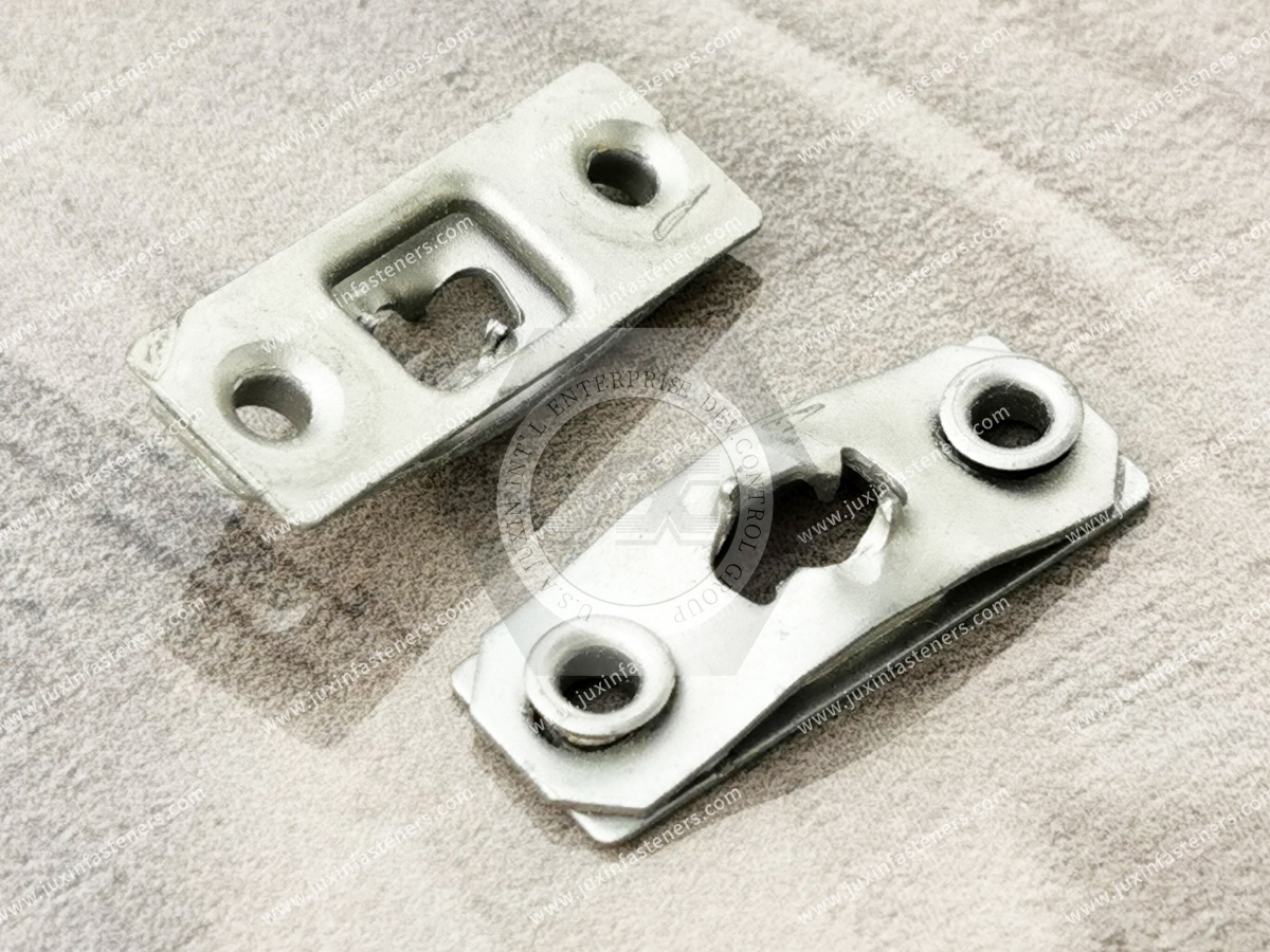
The first design concept defines:
Overall length and width
Material thickness
Throat depth
Spring-leg profile
Entry angle
Panel contact locations
Thread-support geometry
Anti-rotation features
Locating features
Clearance around the screw
Tooling access
Burr orientation
Cut-edge locations
Bend radii
Coating allowance
The design should avoid unnecessary complexity. Every lance, embossment, secondary tab, or severe bend increases tooling, inspection, and production risk.
A custom fastener is only useful if it performs at production limits, not merely at nominal CAD dimensions.
The tolerance analysis should evaluate combinations such as:
Minimum clip opening with maximum panel thickness
Maximum clip opening with minimum panel thickness
Minimum throat depth with minimum panel setback
Maximum throat depth with maximum hole setback
Maximum coating thickness
Worst-case thread-position offset
Maximum bend-angle variation
Maximum burr condition
Minimum available assembly clearance
The customer’s sheet-metal tolerances and the fastener’s production tolerances must be studied together.
Finite element analysis can support custom spring-fastener development when the geometry, material model, or loading condition creates significant uncertainty.
Possible uses include:
Comparing alternative spring-leg profiles
Locating stress concentrations
Estimating elastic deflection
Screening the risk of localized yielding
Comparing installation-force trends
Evaluating material-thickness changes
Reviewing high-deflection concepts
Reducing the number of physical design iterations
However, FEA is not automatically required for every clip-on nut.
Simulation accuracy depends on:
Correct material data
Realistic contact conditions
Friction assumptions
Heat-treated properties
Residual stress
Forming history
Boundary conditions
Mesh quality
Actual panel geometry
Simulation should guide design decisions where justified, but physical testing remains necessary.
A model cannot independently confirm burr effects, coating damage, assembly variability, tool wear, thread quality, or operator handling.
JUXIN FASTENERS evaluates the engineering route according to project complexity.
Analysis, customer-supplied simulation data, external engineering collaboration, or prototype-led development may be used as appropriate; advanced simulation should not be assumed unless included in the agreed project scope.
The prototype route depends on geometry, material, quantity, schedule, and how closely the sample must represent production.
Possible approaches include:
Modified standard components
Soft or simplified tooling
Single-operation prototype tooling
Laser-cut and formed samples
Machined development fixtures
Short-run stamping
Production-intent pilot tooling
Each method has limitations.
A laser-cut and hand-formed sample may be useful for checking envelope and basic fit but may not reproduce:
Production edge condition
Stamping burr
Progressive forming
Work hardening
Heat-treatment distortion
Final spring force
Production coating
High-volume dimensional capability
Prototype results should therefore be classified as:
Concept validation
Fit validation
Functional validation
Production-intent validation
Only production-intent samples should be used for final performance approval.
A custom clip-on nut validation plan may include:
| Test | Engineering purpose |
|---|---|
| Dimensional inspection | Confirms geometry, throat depth, thread position, and critical profile |
| Installation-force test | Verifies the fastener can be installed consistently |
| Retention or pull-off test | Measures resistance to accidental removal before screw installation |
| Seating-depth inspection | Confirms full engagement with the panel edge |
| Screw-entry test | Detects misalignment, binding, and cross-threading risk |
| Thread-gaging | Verifies metric or unified-inch thread acceptance |
| Tightening-torque test | Confirms stability at the production installation setting |
| Strip or failure-torque test | Establishes margin above the specified tightening torque |
| Push-out or displacement test | Evaluates movement during axial screw loading |
| Repeated service-cycle test | Assesses durability during removal and reinstallation |
| Vibration test | Evaluates retention under the intended dynamic environment |
| Thermal-cycle test | Evaluates material and joint behavior across temperature changes |
| Corrosion test | Compares finish performance under the specified method |
| Coating-adhesion review | Identifies cracking or flaking during clip deflection |
| Hydrogen-risk verification | Applies where high-strength electroplated steel requires control |
| Process-capability study | Confirms stable production of critical dimensions |
The acceptance criteria must be agreed before samples are produced. Testing without defined pass/fail limits creates data but not an approval decision.
A custom clip may require high pre-assembly retention so that it remains attached during shipping and line handling. This retention should not be confused with the strength of the completed screw joint.
The completed joint depends on:
Screw strength
Thread engagement
Clip thread strength
Panel support
Tightening torque
Clamp load
Load direction
Joint geometry
Vibration
Service environment
Increasing clip grip does not automatically increase strip torque or structural capacity. In some cases, excessive spring force makes installation difficult without improving the final threaded joint.
The custom design should define separate targets for:
Installation force
Unloaded clip retention
Screw rundown
Tightening torque
Strip or failure torque
Completed-joint load performance
A fastener that works during manual prototype assembly may fail on a high-speed production line.
Automated or semi-automated installation may require:
Controlled presentation orientation
Feed-compatible external geometry
Consistent installation-force window
Positive seating indication
Adequate lead-in
Low risk of nesting or tangling
Stable screw alignment
Compatibility with vision inspection
Defined reject criteria
Repeatable packaging orientation
The production team should review these requirements before tooling release. Feedability and orientation can influence the clip’s external geometry as much as mechanical load requirements do.
The finish must satisfy the operating environment without damaging spring performance or dimensional fit.
Possible requirements include:
Zinc or zinc-alloy electroplating
Zinc-flake coating
Mechanical deposition
Phosphate-based finishes
Organic topcoats
Stainless spring material
Customer-specific coating systems
The engineering review should consider:
Corrosion target
Coating thickness
Color
Friction
Thread fit
Grounding or electrical continuity
Installation wear
Coating flexibility
Panel compatibility
Hydrogen-embrittlement risk
Environmental and customer restrictions
Salt-spray duration alone should not determine coating selection.
The real service environment, failure mechanism, edge damage, galvanic combination, installation abrasion, and maintenance interval also matter.
For hardened electroplated spring components, review Hydrogen Embrittlement Mitigation in High-Strength Spring Steel Fasteners.
After the design passes functional validation, the manufacturing process must be developed for stable volume production.
A production-tooling plan may include:
Strip-layout development
Material-utilization review
Stamping-stage definition
Piercing sequence
Forming sequence
Thread-feature integration
Heat-treatment allowance
Distortion compensation
In-process inspection
Tool-wear controls
Preventive-maintenance planning
Poka-yoke or mistake-proofing
Final inspection fixtures
Tooling cost and lead time depend on:
Component complexity
Number of forming stages
Material thickness
Required tolerances
Thread construction
Annual demand
Tool life
Inspection requirements
Automation level
Secondary operations
The supplier should not quote definitive tooling, sample timing, or production MOQ before reviewing the actual geometry and projected volume.
The first production-intent run should verify more than part appearance.
Pilot validation should examine:
Critical dimensions
Thread gaging
Material certification
Hardness
Heat-treatment consistency
Coating thickness
Installation force
Retention force
Torque performance
Tool-mark condition
Burr direction and height
Packaging behavior
Lot traceability
Process stability
Critical characteristics may require statistical process-capability evaluation according to the customer’s quality plan.
A visually acceptable sample is not sufficient evidence that the process can repeatedly manufacture the approved geometry.
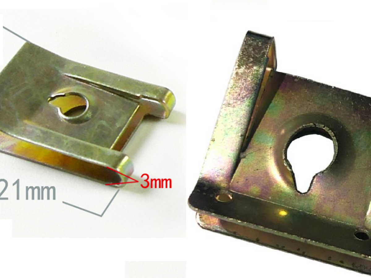
Custom fasteners become part of the customer’s engineered assembly. Uncontrolled changes can affect fit, torque, corrosion, retention, and automated installation.
Change-control requirements should cover:
Raw material
Material supplier
Strip thickness
Heat treatment
Hardness
Tooling
Forming sequence
Thread manufacturing
Coating supplier
Coating chemistry
Coating thickness
Baking process
Inspection method
Production location
Packaging
The required customer-notification and revalidation process should be agreed before serial production.
Custom clip-on nuts may support:
Electronics housings
Serviceable covers
Interior brackets
Underbody shields
Lightweight sheet-metal assemblies
Inverter and charger enclosures
Non-structural battery-pack auxiliary components
Sensor and harness mounting features
Automotive projects may require drawing control, traceability, corrosion validation, vibration testing, production approval documentation, and formal change management.
Custom clips can accommodate:
Narrow folded flanges
Restricted switchgear spaces
Painted enclosure edges
Internal mounting rails
Access doors
Junction boxes
Data-center power equipment
UPS and energy-storage enclosures
Electrical grounding or current-carrying requirements must be evaluated separately and should not be assumed from mechanical fit.
Common applications include:
CNC machine enclosures
Conveyor guards
Compressor panels
Packaging machinery
Pump housings
Service doors
Automation cells
Maintenance covers
Repeated access, vibration, contamination, and operator safety may influence the design.
Rail equipment may require specialized clips for interior panels, equipment cabinets, and serviceable enclosures where vibration, corrosion, limited access, and long maintenance intervals interact.
Low-profile custom clips may support AGV covers, controller housings, sensor brackets, robot enclosures, and compact electronic modules.
Custom clips may be evaluated for qualified aerospace-support equipment, cabin systems, ground equipment, non-flight-critical housings, or other applications governed by the customer’s approved specifications.
No standard industrial clip should be represented as approved for flight-critical or regulated aerospace use without the necessary material, process, testing, traceability, and customer qualification.
A fastener drawing alone cannot define the complete interface.
Minimum and maximum material conditions must be provided.
Coating can change grip range, thread fit, installation force, and electrical performance.
An extremely tight clip may create operator injury risk, coating damage, or automated assembly jams.
Simulation cannot replace physical production-intent testing.
Prototype forming may not represent progressive stamping and heat treatment.
Volume determines whether modification, soft tooling, staged tooling, or full progressive tooling is commercially appropriate.
A small change in hole setback, flange width, bend radius, or coating can invalidate the approved fastener interface.
A custom spring-fastener drawing should define:
Approved component geometry
Functional datums
Critical dimensions
Throat depth
Grip range
Thread position
Metric or inch thread specification
Material
Material thickness
Hardness
Heat treatment
Surface finish
Coating thickness
Burr direction
Critical bend radii
Installation direction
Installation-force requirement
Retention-force requirement
Target tightening torque
Minimum failure criterion
Corrosion requirement
Hydrogen-control requirement where applicable
Inspection method
Lot traceability
Packaging
Customer approval status
A complete drawing reduces ambiguity between engineering, procurement, tooling, heat treatment, coating, quality control, and production.
When submitting a project to JUXIN FASTENERS, provide as much of the following information as possible.
2D panel drawing
3D assembly model
Panel-edge detail
Flange width
Bend radius
Hole diameter
Hole setback
Adjacent components
Maximum fastener envelope
Installation direction
Tool-access direction
Material
Minimum and maximum thickness
Coating or paint
Final thickness after coating where critical
Burr and edge requirements
Forming tolerances
Diameter
Pitch or thread series
Length
Head style
Strength class or grade
Surface finish
Installation torque
Driver type
Automated or manual installation
Maximum installation force
Minimum retention force
Target tightening torque
Minimum strip or failure torque
Tensile or shear load
Vibration requirement
Temperature range
Service cycles
Corrosion requirement
Electrical requirements where applicable
Applicable ISO, EN, DIN, ASTM, ASME, SAE, or customer specification
Material certification
Inspection report
Traceability
Sample approval requirements
Production approval documentation
Restricted substances requirements
Change-notification requirements
Prototype quantity
Initial production quantity
Estimated annual demand
Program duration
Target sample date
Production launch date
Packaging
Delivery destination
JUXIN FASTENERS supports drawing-based development and production sourcing for custom clip-on nuts and spring fasteners.
Project support may include:
Application and drawing review
Standard-product gap analysis
U-nut and J-nut geometry selection
Custom throat-depth evaluation
Panel-range review
Metric and inch thread selection
Material and coating comparison
Prototype-route evaluation
Sample coordination
Fit and torque-test planning
Tooling feasibility review
Pilot production planning
Quality-documentation alignment
Annual-volume quotation
The exact engineering, simulation, tooling, testing, documentation, and production scope is defined according to the project’s technical requirements and commercial volume.
A custom component is appropriate when standard products cannot meet the panel geometry, hole setback, grip range,
installation envelope, retention, thread location, environmental, or assembly-process requirements.
The supplier needs the mating panel geometry, thickness range, hole location, bend radius, screw specification, installation direction, available envelope,
force and torque targets, environment, validation criteria, and projected volume.
No. FEA can be useful for complex or high-risk designs, but many projects can be developed through dimensional analysis and controlled prototype testing.
Physical validation remains necessary in either case.
A sample can support preliminary evaluation, but production development should use controlled drawings and agreed acceptance criteria.
Reverse dimensions alone do not reveal the original material, hardness, performance targets, or tolerance intent.
Potentially, but the achievable range depends on geometry, material, installation force, retention target, and permitted spring stress. Minimum and maximum conditions must be tested.
Tooling depends on component complexity, forming stages, material, tolerance, thread feature, production volume, automation, tool life, and inspection requirements.
Accurate tooling quotations require drawing review.
There is no universal MOQ. Commercial feasibility depends on tooling investment, component weight, material, complexity, annual demand, secondary processes,
and packaging. Projected annual usage should be included in the RFQ.
Sometimes, but not automatically. Spring properties, formability, work hardening, galling, strength, corrosion environment, magnetic requirements, and cost must be evaluated.
A 3D model is valuable for application review, but a controlled 2D drawing is normally required to define tolerances, material, finish, thread, performance, inspection, and acceptance requirements.
Approval should include dimensional inspection and agreed functional tests using production-intent panel material, coating, screw, and assembly conditions.
If a standard U-nut, J-nut, clip-on nut, barrel clip nut, or spring fastener cannot meet your assembly requirements, JUXIN FASTENERS can evaluate a custom drawing-based solution.
Send your available technical and commercial information to:
Please include:
2D drawing
3D model where available
Panel material and thickness range
Flange and hole geometry
Mating screw specification
Available installation envelope
Installation and retention targets
Tightening and failure-torque requirements
Operating environment
Required standards and documentation
Prototype quantity
Estimated annual demand
Target project schedule
A complete RFQ allows the engineering and sourcing teams to evaluate technical feasibility, prototype strategy, tooling requirements, validation scope, production risk, and commercial viability more efficiently.
 MORE NEWS
Sep. 22, 2026
Sep. 22, 2026
Sep. 22, 2026
Contact Us
Tel.:
+86 020 8621 0320
+86 020 3121 6067
E-mail:
Technical Support:
Navigation
SEND INQUIREY