
Call Us
+86 136 6007 9809
Call Us
+86 136 6007 9809

Aug. 30, 2026
Industrial robots and precision automation systems depend on mechanical assemblies that must maintain alignment,
repeatability and structural integrity through repeated motion, acceleration, vibration and production cycles.
Fasteners in these systems do more than hold components together.
They can influence joint stability, component positioning, serviceability, assembly efficiency and the repeatability of assemblies containing actuators,
sensors, machine-vision systems, control hardware and motion components.
For design engineers, the challenge is therefore not simply choosing a screw or nut of the correct size. The fastening method should match the function of the joint,
substrate material, loading condition, assembly sequence, installation access, maintenance requirement and required positioning accuracy.
For procurement and sourcing teams, another challenge appears when a robotic system combines standard industrial fasteners with drawing-specific pins, shafts, spacers,
bushings, threaded components and other precision mechanical parts.
JUXIN FASTENERS supplies industrial fasteners and custom CNC machined components for robotics, automation equipment and precision machinery,
supporting standard fastening requirements as well as drawing-based OEM components.
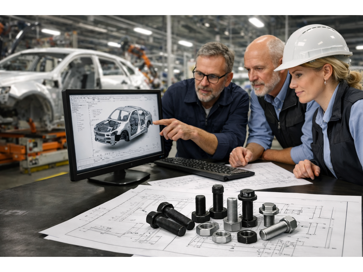
A modern industrial robot or automated production system can contain mechanical connection points across structural, motion, sensing, electrical and protective assemblies.
Typical applications include:
Industrial robotic arms
Collaborative robots
Automated assembly equipment
Pick-and-place systems
Machine-vision equipment
Motion-control systems
End-of-arm tooling
Robotic grippers
Automated inspection equipment
Control cabinets and electrical enclosures
Precision positioning systems
Semiconductor and electronics automation equipment
Material-handling systems
Custom production machinery
The appropriate fastening solution can vary significantly between these locations.
A structural frame connection, for example, has different requirements from a removable sensor bracket, a sheet-metal control enclosure or a precision alignment component inside a motion assembly.
This is why fastener selection for industrial robotics should begin with the function of the joint rather than simply with the fastener catalog.
Different areas of a robotic system create different fastening requirements.
A useful engineering approach is to identify what the component must actually do before selecting the fastening technology.
The function may be:
Structural clamping
Creating a permanent threaded attachment point
Preventing unintended loosening
Locating a component accurately
Maintaining a defined spacing
Guiding movement
Retaining a removable panel
Mounting sensors or electronics
Providing electrical isolation
Supporting repeated maintenance access
Once the function is clear, engineers can evaluate whether the requirement is best served by a standard fastener, a specialized fastening system or a drawing-based precision component.
Robot bases, frames, support structures and equipment housings require mechanically stable joints capable of maintaining assembly integrity under the expected operating conditions.
Depending on the design, suitable components may include:
Hex bolts
Socket head cap screws
Machine screws
Nuts
Locking nuts
Washers
Studs
Weld fasteners
Self-clinching fasteners
Blind rivet nuts
The appropriate solution depends on factors such as installation access, sheet thickness, substrate material, joint loading, manufacturing process and whether the connection must be removable.
For fabricated sheet-metal structures, creating a permanent threaded attachment point can eliminate the need to hold a loose nut on the opposite side during final assembly.
Self-clinching fasteners, blind rivet nuts and weld nuts can all create captive threaded attachment points, but they should not be treated as interchangeable products.
A self-clinching fastener depends on a suitable sheet material, thickness and installation condition.
A blind rivet nut can be useful where installation is performed from one side of a panel.
A weld nut may be appropriate when the manufacturing process already supports welding and a permanent threaded attachment is required.
The correct choice depends on the complete assembly rather than the thread size alone.
Moving assemblies introduce additional engineering considerations.
Robotic joints, linear motion systems, actuators and precision mechanisms may contain combinations of:
Precision screws
Threaded components
Shafts
Pins
Bushings
Sleeves
Spacers
Retaining components
Custom CNC machined parts
Repeated acceleration, deceleration and directional changes can introduce cyclic loading and vibration into the mechanical assembly.
Fastener selection should therefore consider more than nominal fastener strength.
Depending on the joint, engineers may also need to evaluate:
Required preload
Joint stiffness
Mating materials
Surface condition
Friction
Repeated transverse loading
Settlement or embedment
Thermal effects
Tightening method
Locking method
Maintenance frequency
Where positional accuracy depends on component geometry, a conventional threaded fastener should not automatically be expected to perform the function of a precision locating component.
This distinction becomes particularly important in industrial robotics and precision automation equipment.
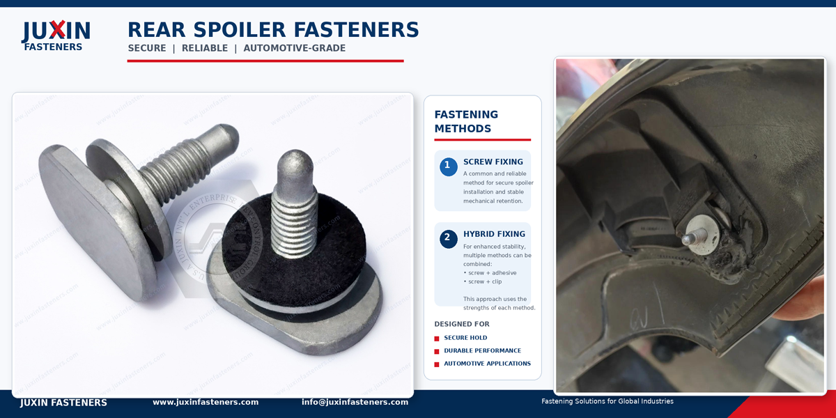
One useful design question is whether a component is intended to clamp an assembly or locate it accurately.
These are not necessarily the same mechanical function.
In many bolted assemblies, the primary purpose of the bolt is to generate clamp load.
If accurate component location is critical, engineers may instead use dedicated locating features such as:
Dowel pins
Alignment pins
Precision shoulders
Piloted components
Machined locating surfaces
Custom shafts or pins
Clamping keeps the joint together.
Locating controls component position.
If a conventional bolt is expected to perform both functions without evaluating hole clearance and mating geometry, assembly position may become more dependent on dimensional variation.
For precision automation equipment, separating the clamping and locating functions can provide a clearer tolerance strategy and more repeatable assembly.
Robotic equipment frequently contains components that must return to predictable positions after assembly, adjustment or maintenance.
Engineers may therefore need to evaluate:
Critical dimensions
Hole locations
Thread fit
Shoulder dimensions
Concentricity requirements
Component length
Spacer height
Mating geometry
Surface finish
Assembly sequence
Positioning method
Tolerance stack-up
Not every dimension needs to be controlled to the tightest possible tolerance.
The more important engineering question is:
Which dimensions actually affect the function of the robotic assembly?
Tightening every tolerance can increase manufacturing cost without necessarily improving equipment performance.
A more practical approach is to identify the functional interfaces first and apply appropriate controls to the dimensions that influence positioning, movement, fit or assembly.
Spacers, standoffs, bushings, pins and sleeves may appear to be relatively simple components, but their dimensions can influence the final position of sensors, brackets, covers or motion components.
Consider an assembly containing several interfaces:
Frame → Bracket → Spacer → Sensor Mount → Fastener → Mating Component
Variation may originate at every interface.
Each individual component may satisfy its own drawing requirements while accumulated variation still influences the final position of the assembly.
This can be particularly relevant where mechanical components support:
Machine-vision cameras
Optical sensors
Encoders
Proximity sensors
Precision guides
Linear motion components
Measurement systems
For precision automation equipment, engineers should therefore evaluate the complete tolerance chain rather than considering each fastener, spacer or mounting component in isolation.
Industrial automation systems increasingly integrate cameras, sensors, encoders and electronic control hardware.
These components can require smaller fastening hardware and more compact mounting arrangements than structural robot assemblies.
Depending on the equipment design, potential components include:
Precision machine screws
Small-diameter screws
Threaded standoffs
Spacers
Self-clinching standoffs
Captive fasteners
Plastic or nylon hardware
Alignment components
Custom machined mounting parts
Design considerations may include:
Available installation space
Component positioning
Service access
Electrical isolation
Equipment weight
Tool clearance
Resistance to unintended loosening
Required spacing between components
Where circuit boards or electronic components are involved, plastic and nylon fasteners may also be considered when electrical insulation, low weight or a non-metallic component is appropriate for the design.
Material suitability should always be evaluated against the actual mechanical, thermal and environmental requirements of the application.
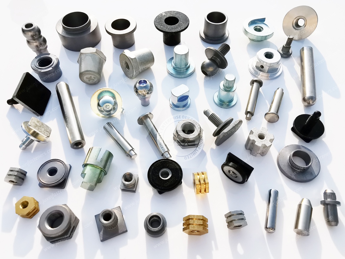
Industrial robots normally operate as part of a larger automation architecture that can include control cabinets, electrical enclosures, power electronics, communication equipment and safety systems.
Sheet-metal cabinets may use:
Self-clinching nuts
Self-clinching studs
Self-clinching standoffs
Blind rivet nuts
Weld nuts
Weld studs
Captive screws
Machine screws
Plastic fasteners
Cable-management hardware
These fastening technologies can create permanent or captive attachment points and reduce dependence on loose hardware during equipment assembly and maintenance.
The selection process should consider:
Sheet material
Sheet thickness
Backside access
Installation process
Required thread size
Service frequency
Joint loading
Equipment assembly sequence
For example, a blind rivet nut may solve a one-sided installation problem, while a self-clinching nut may be better integrated into a sheet-metal fabrication process where suitable press installation is available.
The best solution depends on the manufacturing and assembly process as well as the final application.
Not every joint in industrial robotics should be treated as a permanent connection.
Protective covers, access panels, electronics housings and maintenance interfaces may be opened repeatedly during the life of the equipment.
For these applications, designers should consider:
Frequency of access
Risk of loose hardware entering equipment
Tool accessibility
Thread durability
Assembly and service time
Replacement requirements
Panel thickness
Available installation space
Captive fastening solutions may be useful where retaining the screw with the panel or component can simplify maintenance and reduce loose hardware.
However, the appropriate configuration depends on the actual panel design, service procedure and installation requirements.
Industrial robotics frequently involves repeated movement and vibration.
However, simply selecting a component described as an anti-vibration or locking fastener does not automatically create a reliable joint.
A bolted joint should be considered as a complete mechanical system.
Factors may include:
Bolt preload
Joint stiffness
Mating surface condition
Friction
Embedment
Repeated transverse loading
Thermal changes
Material behavior
Tightening method
Locking method
Depending on the application, engineers may evaluate prevailing-torque nuts, all-metal locking nuts, nylon-insert lock nuts or other locking features.
The suitable solution depends on factors such as temperature, vibration, maintenance requirements, mating fastener and application environment.
A locking feature should complement a properly designed joint rather than compensate for an unsuitable joint design.
One of the most useful decisions during robotics equipment development is determining whether the application genuinely requires a custom component.
Not every special-looking assembly requires a custom fastener.
At the same time, forcing a standard screw, bolt or spacer into a precision mechanical function can make the overall assembly more complicated.
A standard fastener may be suitable when:
Standard geometry satisfies the assembly
A standard thread form is suitable
The component primarily provides clamping
No special locating geometry is required
Standard material options meet the application
Available surface finishes meet the environmental requirement
Standard dimensions fit the installation envelope
Using established standard components where appropriate can simplify sourcing and avoid unnecessary manufacturing complexity.
A drawing-based CNC component may be considered when:
A shoulder controls component position or movement
A non-standard shaft diameter is required
Multiple diameters are integrated into one component
A spacer length is functionally critical
Concentric features are required
A pin provides alignment or guidance
Special thread-to-body geometry is needed
Standard hardware interferes with surrounding equipment
Several mechanical functions can reasonably be integrated into one component
The part must match an existing OEM drawing or assembly
The decision should be based on function, manufacturability, assembly requirements and sourcing considerations rather than customization for its own sake.
In addition to industrial fasteners, JUXIN FASTENERS supports drawing-based CNC machined components for robotics and automation assemblies.
Typical component categories can include:
Alignment pins
Guide pins
Shafts
Bushings
Spacers
Sleeves
Standoffs
Threaded pins
Stepped components
Custom threaded components
CNC turned parts
CNC machined brackets
Drawing-specific mechanical components
These components can be manufactured according to customer drawings, specifications and approved samples where appropriate.
The suitable manufacturing route depends on component geometry, material, tolerance, quantity and application requirements.
For OEM sourcing, clearly identifying critical dimensions and functional features can help distinguish necessary engineering requirements from dimensions that can follow normal manufacturing practice.
Material selection should reflect the mechanical and environmental requirements of the assembly.
Depending on the component design, potential material families may include:
Carbon steel
Alloy steel
Stainless steel
Aluminum
Brass
Engineering plastics
No single material is appropriate for every robotics application.
Engineers may need to consider:
Mechanical loading
Wear
Corrosion environment
Component weight
Electrical requirements
Operating temperature
Mating materials
Surface treatment
Manufacturing process
Material selection should also be considered together with the required surface condition or coating.
A surface treatment can influence corrosion protection, friction, appearance and compatibility with the surrounding assembly.
The appropriate specification therefore depends on the actual component and operating environment.
A fastener can satisfy mechanical requirements and still create manufacturing problems if installation access has not been considered.
Before finalizing a fastening method, robotics equipment designers can ask:
Can both sides of the joint be accessed?
Is there sufficient clearance for the installation tool?
Will installation be manual or automated?
Does the fastener need to remain captive?
Will technicians remove the component repeatedly?
Could loose hardware fall into sensitive equipment?
Is the thread created before or after enclosure assembly?
Does the joint require positioning as well as clamping?
Can the fastener be inspected efficiently during production?
Does the fastening method fit the intended manufacturing sequence?
These questions can influence the choice between conventional nuts and bolts, self-clinching fasteners, blind rivet nuts, weld fasteners, captive fasteners and custom components.
| Assembly Area | Typical Engineering Need | Potential Fastening or Component Options |
|---|---|---|
| Robot frame and base | Structural clamping | Bolts, screws, nuts, washers, studs |
| Fabricated sheet-metal structure | Permanent threaded attachment | Weld nuts, weld studs, self-clinching fasteners, blind rivet nuts |
| Robot joint or actuator | Motion and mechanical retention | Precision screws, threaded components, shafts, pins, bushings |
| Precision positioning assembly | Repeatable component location | Alignment pins, dowels, shoulders, custom CNC components |
| Sensor or vision mounting | Compact and repeatable mounting | Precision screws, spacers, standoffs, alignment components |
| Control cabinet | Captive threads in sheet metal | Self-clinching fasteners, blind rivet nuts, weld fasteners |
| Electronics or PCB assembly | Mounting, spacing or insulation | Standoffs, spacers, plastic and nylon hardware |
| Service panel | Repeated access | Captive fastening solutions, machine screws |
| Custom mechanism | Drawing-specific geometry | CNC pins, shafts, sleeves, spacers, bushings and threaded components |
This selection guide is a starting point rather than a universal specification.
Final component selection should be based on the actual assembly design, material, loading, installation process and operating conditions.
Before specifying a fastening solution, engineers can work through a practical sequence.
Determine whether the component is primarily responsible for:
Clamping
Locating
Spacing
Guiding
Retaining
Electrical isolation
Service access
This prevents a standard threaded fastener from being assigned a precision function that may be better handled by another component.
Confirm:
Material
Sheet or component thickness
Hole geometry
Mating component
Available edge distance
Backside access
This is particularly important when selecting self-clinching fasteners, blind rivet nuts, weld fasteners or threaded inserts.
Consider whether the joint experiences:
Static loading
Repeated movement
Vibration
Transverse loading
Thermal cycling
Frequent disassembly
The fastening and locking strategy should reflect the actual operating condition.
Determine which dimensions affect:
Alignment
Motion
Sensor position
Component spacing
Assembly fit
Interference with surrounding parts
Avoid applying unnecessarily tight tolerances to non-functional dimensions.
Determine:
Installation direction
Tool access
Assembly sequence
Whether one-sided installation is required
Whether the component must remain captive
How frequently the joint will be serviced
Use standard hardware where it meets the functional requirement.
Move to a custom fastener or CNC machined component when the geometry, positioning function, integration requirement or existing OEM design genuinely requires it.
This decision process can reduce unnecessary customization while helping engineers identify the locations where a drawing-specific component provides real value.
A technically complete RFQ can reduce unnecessary clarification between engineering, procurement and the supplier.
Where available, provide:
2D engineering drawing
3D model
Part number
Fastener or component type
Thread specification
Critical dimensions
Critical tolerances
Material
Heat-treatment requirement, if applicable
Surface finish or coating
Functional requirements
Mating component information where relevant
Prototype or sample requirement
Estimated order quantity
Expected production volume
Inspection or documentation requirements
Packaging requirements
If a component is being sourced as an alternative to an existing part, an approved physical sample may also help clarify geometry and functional requirements where appropriate.
For drawing-based parts, clearly identifying critical characteristics can help the supplier focus manufacturing and inspection controls on the features that actually affect the assembly.
Robotics and automation equipment frequently combines commodity hardware with application-specific fasteners and drawing-based precision components.
Procurement teams can therefore separate sourcing requirements into three broad categories.
Standard fasteners are established screws, bolts, nuts, washers and related hardware that can be specified using recognized dimensions, materials and performance requirements.
Application-specific fasteners use established fastening technologies but may require a particular material, finish, dimension, locking feature or configuration.
Drawing-based precision components include pins, shafts, bushings, spacers, sleeves and threaded components whose geometry is primarily controlled by the OEM drawing.
Separating these categories can improve RFQ clarity.
It can also help avoid applying unnecessary custom manufacturing requirements to standard hardware while ensuring that truly functional dimensions on precision components receive appropriate attention.
For projects containing multiple small mechanical parts, procurement teams may also evaluate whether related fasteners and CNC components can be sourced together to simplify supplier coordination.
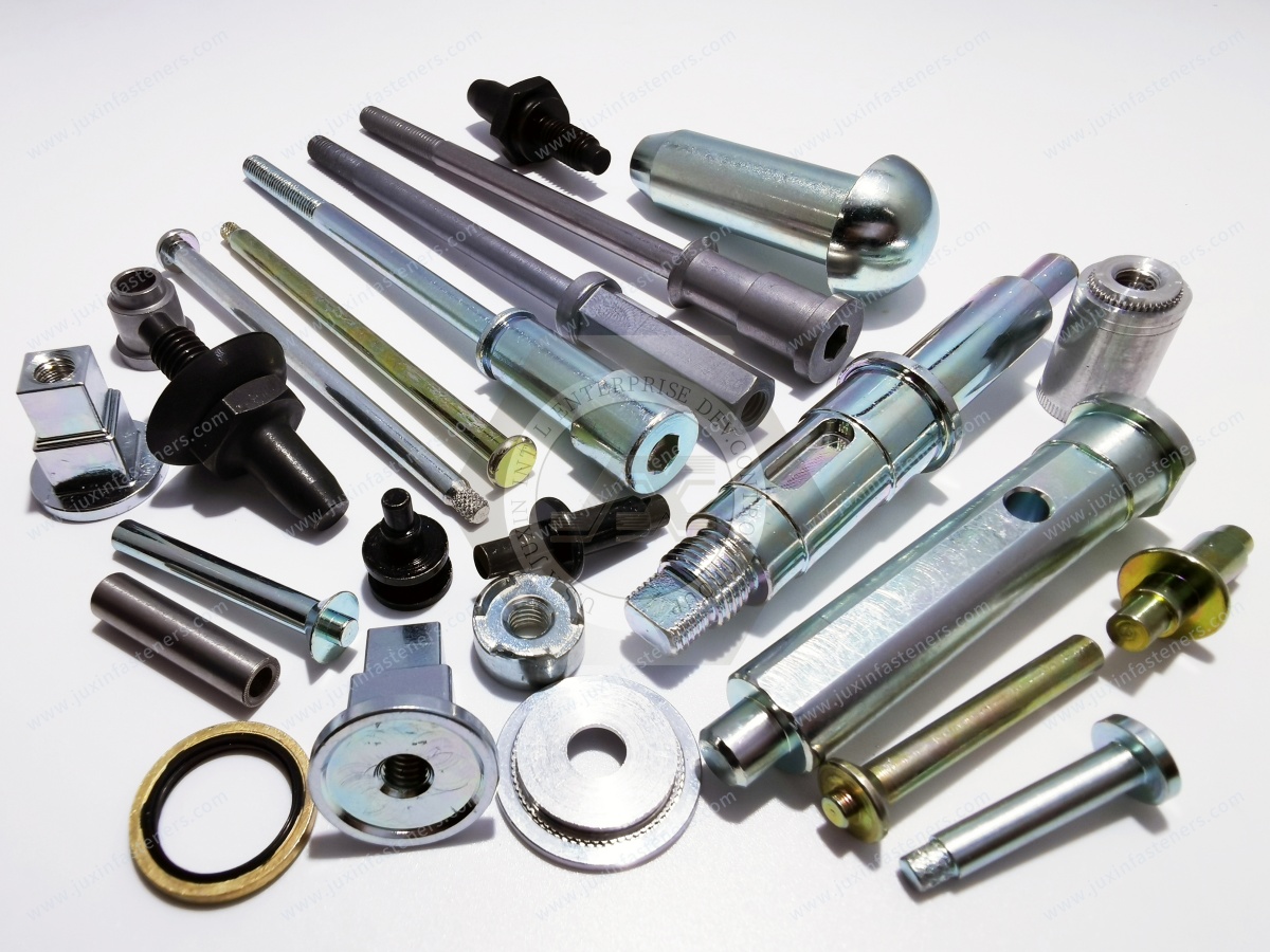
Before a fastener or precision component is released for sourcing, engineering and procurement teams can review:
What is the actual function of this component?
Is it clamping, locating, spacing, guiding or retaining?
Can a standard fastener perform the function?
Which dimensions are functionally critical?
Are any tolerances tighter than the assembly actually requires?
Is the selected material appropriate for the operating environment?
Is the surface treatment compatible with the mating components?
Is sufficient installation access available?
Will the component require repeated removal?
Is vibration or cyclic loading relevant?
Is one-sided installation required?
Does the supplier need mating-part information to evaluate the component?
Are inspection requirements clearly identified?
Are prototype and production quantities defined?
These questions can help reduce over-specification while improving communication between design engineering, procurement and manufacturing.
Industrial robotics requires more than a list of screws and bolts.
A practical fastening strategy begins by understanding what each connection must accomplish within the mechanical system.
Structural joints require appropriate clamping.
Precision mechanisms may require dedicated locating features.
Sensors and machine-vision systems may depend on repeatable positioning.
Control cabinets require efficient sheet-metal fastening.
Electronics may require spacing or electrical isolation.
Service panels require maintainable connections.
Custom mechanisms may require drawing-based pins, shafts, spacers, bushings, sleeves or threaded components.
JUXIN FASTENERS supports OEM and industrial customers with standard and customized fasteners together with precision CNC machined components for robotics,
automation equipment and industrial machinery.
Our product and manufacturing scope can support projects involving standard fastening hardware,
application-specific fasteners and drawing-based mechanical components, depending on the design and sourcing requirements.
For a new industrial robotics or precision automation project, send the available drawing, material requirement, thread specification,
critical dimensions, tolerances, surface treatment and estimated quantity for technical review and quotation.
Email: info@juxinfasteners.com
Website: www.juxinfasteners.com
 MORE NEWS

Sep. 25, 2026

Sep. 25, 2026

Sep. 25, 2026
Contact Us
Tel.:
+86 020 8621 0320
+86 020 3121 6067
E-mail:
Technical Support:
Navigation
SEND INQUIREY