
Call Us
+86 136 6007 9809
Call Us
+86 136 6007 9809

Aug. 12, 2026
Why does an industrial shaft sometimes fail even when the material certificate, tensile strength and hardness all meet specification?
Because shaft reliability is not controlled by material strength alone.
In rotating machinery, fatigue cracks frequently initiate at local geometric features such as:
Shaft shoulders
Keyways
Spline roots
Retaining-ring grooves
Relief grooves
Cross holes
Thread run-outs
Diameter transitions
A shaft can therefore pass material inspection and still fail prematurely if local stress, surface condition, heat treatment, machining or assembly conditions were not properly controlled.
For OEM design engineers, mechanical engineers, procurement managers and supplier-development teams, the more useful engineering relationship is:
Shaft Reliability = Load Spectrum + Geometry + Material + Heat Treatment + Surface Condition + Manufacturing Quality + Assembly + Operating Environment
This article focuses specifically on industrial shaft failure prevention and structural integrity.
For basic material selection, material-grade comparisons and general shaft material guidance, use the related JUXIN FASTENERS Precision Shaft Material Selection engineering resource.
There is rarely one universal cause.
A useful failure-analysis sequence is:
Where Did It Fail? → What Load Was Present? → What Geometry Was at the Failure Location? → What Material and Heat Treatment Were Used?
→ What Was the Surface Condition? → How Was the Shaft Manufactured and Assembled? → What Changed in Service?
Common root causes include:
Stress concentration
Cyclic fatigue
Torsional overload
Bending overload
Incorrect material or heat treatment
Surface defects
Improper fits or misalignment
Wear
Corrosion-assisted damage
Manufacturing or grinding defects
The central engineering rule is:
Higher Material Strength ≠ Automatically Higher Shaft Reliability.
Before changing the steel grade, identify the actual failure mechanism.
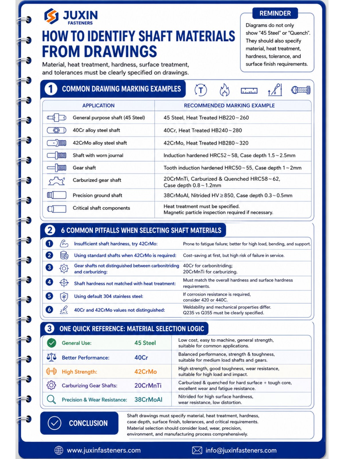
1. The Core Logic of Shaft Material Selection
When engineering industrial shafts, material selection generally follows a tiered approach based on load, torque, fatigue resistance, and environmental conditions.
A quick, field-proven rule of thumb for engineering teams is:
Standard Applications: Grade 1045 Carbon Steel (45#)
Enhanced Stability & Uniformity: Grade 5140 Alloy Steel (40Cr)
Heavy-Duty & High-Strength: Grade 4140 Chromoly Steel (42CrMo)
Integral Gear Shafts: Grade 5120/8620 Case-Hardening Steel (20CrMnTi)
Precision & High Wear Resistance: Grade 41AlCrMo7 Nitriding Steel (38CrMoAl)
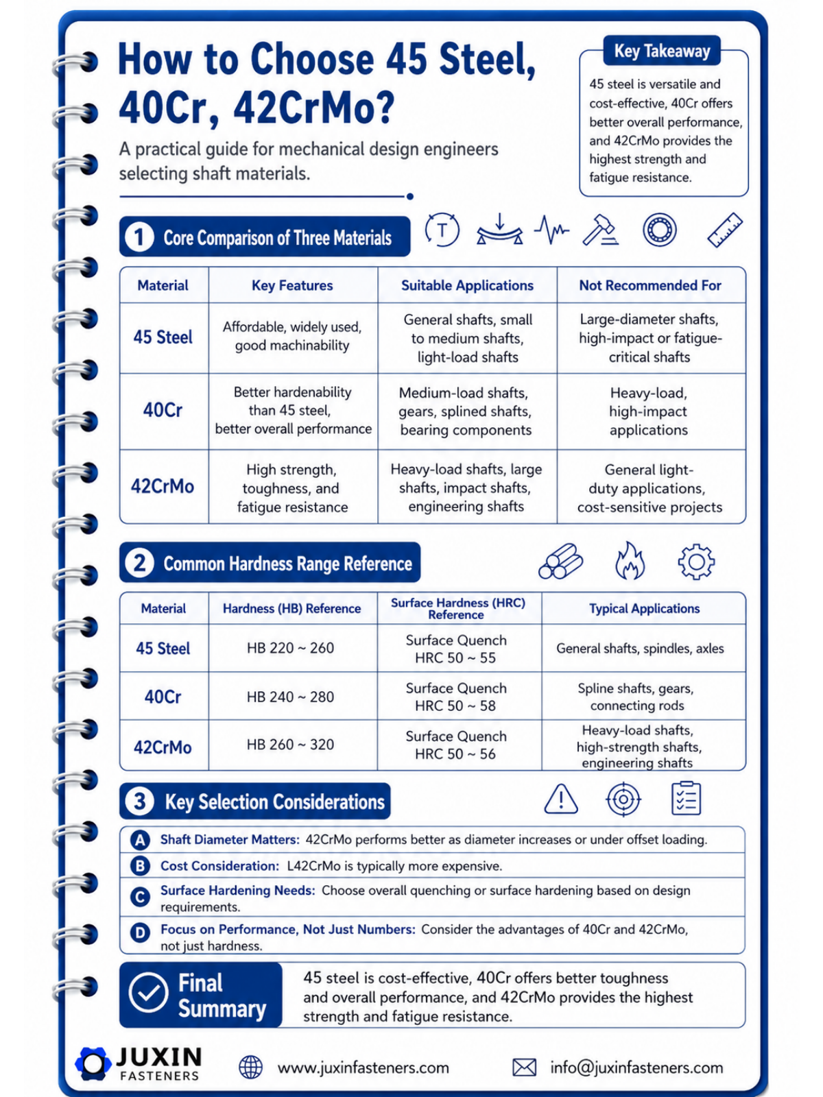
2. Deep Dive: Comparing 1045 (45#), 5140 (40Cr), and 4140 (42CrMo)
These three grades represent the vast majority of medium-carbon and alloy steels used in custom shaft manufacturing.
Understanding their distinct boundaries ensures you do not over-engineer or under-specify.
International Grade | Common Equivalent | Core Strengthening Mechanism | Primary Application Threshold |
AISI 1045 / DIN C45 | 45# | Quenched & Tempered (Q&T) / Induction Hardened | General drive shafts, low-to-medium torque, cost-sensitive projects. |
AISI 5140 / DIN 41Cr4 | 40Cr | Chromium Alloyed + Q&T | High hardenability requirements, medium loads, enhanced core toughness. |
AISI 4140 / DIN 42CrMo4 | 42CrMo | Cr-Mo Alloyed + Premium Q&T | Heavy-duty power transmission, high fatigue limits, impact resistance. |
A shaft may operate below its static yield strength and still fail after repeated cycles.
Why?
Because rotating shafts frequently experience cyclic loading.
A shaft carrying a pulley, gear, sprocket or coupling can be subjected to:
Alternating bending
Repeated torsion
Combined bending and torsion
Start-stop cycles
Shock loads
Load reversals
A component that survives one load event may not survive millions of repeated cycles.
Therefore:
Static Strength ≠ Fatigue Performance.
And:
Peak Torque Capacity ≠ Complete Shaft Reliability.
Basic shaft calculations often begin with nominal stress based on shaft diameter.
But real shafts are rarely perfect cylinders.
They contain features required for assembly and power transmission.
These features modify the local stress field.
A critical distinction is:
Nominal Stress ≠ Local Peak Stress.
A shaft may therefore appear adequately sized in a simplified calculation while experiencing much higher local stress near a shoulder, keyway or groove.
This is why failure analysis should start with the fracture location rather than immediately blaming the material.
Diameter changes are necessary for:
Bearing positioning
Gear location
Seal interfaces
Assembly
Axial retention
But an abrupt diameter transition creates stress concentration.
Important design variables include:
Diameter ratio
Fillet radius
Surface finish
Adjacent bearing or component geometry
Applied bending moment
Applied torque
A very small radius may simplify packaging but increase local fatigue stress.
A larger radius may improve fatigue behavior but interfere with the mating bearing or component.
This creates a genuine design trade-off:
Fatigue Improvement ↔ Assembly Geometry
The correct solution may require:
Appropriate shoulder radius
Bearing chamfer compatibility
Spacer design
Relief geometry
Revised diameter transition
Simply specifying a stronger material does not remove the geometric stress concentration.
Keyways are widely used for torque transmission, but machining a keyway removes material and introduces local geometry that can increase stress.
Potential concerns include:
Keyway root geometry
Key fit
Surface finish
Keyway termination
Shaft diameter
Torque reversals
Bending at the keyway location
When a shaft repeatedly fails at a keyway, the correct investigation is not:
"Which stronger steel should we buy?"
Instead evaluate:
Torque + Bending + Keyway Geometry + Fit + Surface + Material + Heat Treatment
Alternative torque-transfer strategies may sometimes reduce the local stress problem, depending on the application.
Spline shafts distribute torque through multiple teeth, but actual performance depends on more than tooth count.
Important variables include:
Spline geometry
Fit
Tooth alignment
Root geometry
Engagement length
Material
Surface hardness
Lubrication
Manufacturing accuracy
Potential failure modes include:
Spline wear
Tooth flank damage
Root fatigue
Fretting
Local overload
Therefore:
Spline Engagement ≠ Automatically Uniform Load Distribution.
Manufacturing errors or misalignment can cause some spline teeth to carry more load than others.
Retaining-ring grooves are small features with potentially large structural consequences.
A groove:
Reduces effective shaft cross-section
Changes local stiffness
Creates a geometric discontinuity
If the groove is located in a highly stressed region, fatigue risk can increase.
The same principle applies to:
Grinding reliefs
Undercuts
Seal grooves
Thread reliefs
The engineering question should always be:
What stress exists at this feature during the real operating cycle?
Threads create a series of geometric notches.
Thread run-out regions can become especially important where cyclic loading is present.
Relevant design variables include:
Thread size
Root geometry
Thread manufacturing method
Run-out geometry
Surface condition
Transition into the shaft body
Applied bending and torsion
A threaded shaft should therefore be evaluated as a complete fatigue-loaded component rather than simply as a shaft with an added thread.
Cross holes may be required for:
Pins
Lubrication
Locking
Assembly
But a hole through a shaft changes both the effective section and local stress distribution.
If a cross hole is positioned in a region of high bending or torsion, it may become a fatigue initiation site.
Again:
Manufacturing Convenience ≠ Structurally Neutral Feature.
Suppose a medium-carbon steel shaft repeatedly fractures at the same shoulder.
The first response might be:
Upgrade to alloy steel.
That may increase strength.
But if the dominant problem is:
Severe stress concentration
Poor surface finish
Incorrect fillet
Misalignment
Excessive bending
the upgraded material may only delay the same failure.
A better engineering process is:
Failure Location → Failure Mode → Root Cause → Design Correction → Material Review
not:
Failure → Stronger Material
Geometry does not make material selection irrelevant.
Material must provide the required combination of:
Strength
Toughness
Hardenability
Fatigue performance
Wear behavior
Corrosion resistance
Machinability
Heat-treatment response
Common international material families used for shaft engineering may include:
AISI 1045 / EN C45-type medium-carbon steel
SAE 5140 / EN 41Cr4-type chromium alloy steel
SAE 4140 / EN 42CrMo4-type Cr-Mo alloy steel
SAE 8620-type case-hardening steel
Stainless steels
Precipitation-hardening stainless steels
Aluminum alloys
Titanium alloys
However, regional grades should not be assumed to be exact equivalents simply because their chemistry appears similar.
Similar Material Name ≠ Automatic Material Equivalence.
Medium-carbon steel can be appropriate for many general-purpose shaft applications.
Potential applications include:
Conveyor shafts
General transmission shafts
Pump shafts
Motor shafts
Industrial machinery
Advantages can include:
Cost efficiency
Machinability
Availability
Useful response to selected heat treatments
But suitability depends on actual shaft diameter, loading and required properties.
A material family should never be approved from the application name alone.
Chromium alloy steels may be considered where engineers require improved hardenability or mechanical properties compared with a general medium-carbon steel.
Potential applications can include:
Transmission shafts
Spline shafts
Machinery shafts
Gearbox components
But:
Alloy Steel ≠ Automatically Fatigue-Proof.
Geometry and surface condition remain important.
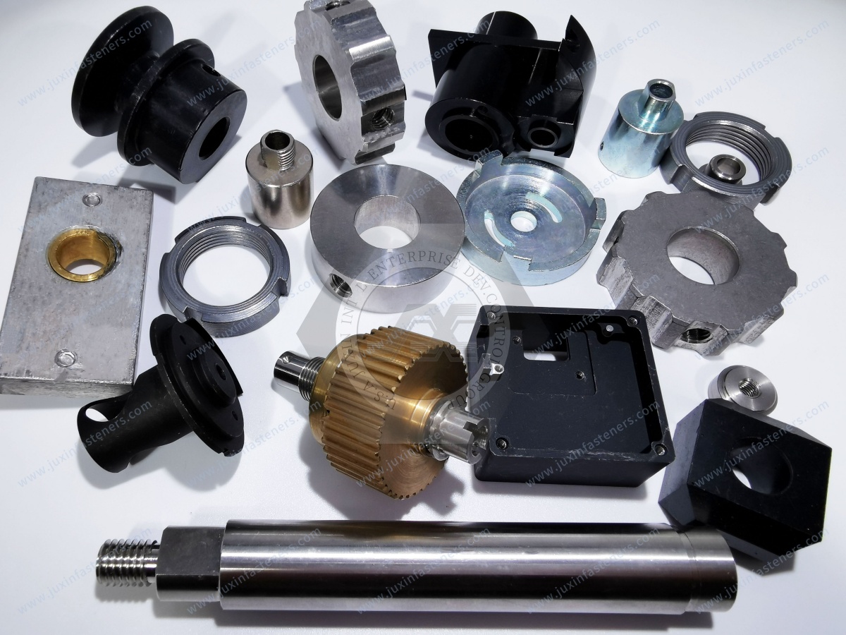
Cr-Mo alloy steels are frequently considered for demanding shaft applications requiring combinations of:
Strength
Toughness
Hardenability
Impact resistance
Potential applications include:
Heavy-duty drive shafts
Construction equipment
Industrial transmissions
Hydraulic machinery
High-load spline shafts
However:
4140 / 42CrMo4 ≠ Complete Shaft Specification.
The drawing must also define the required material condition and finished properties.
Some gear shafts require:
Hard Wear-Resistant Surface + Tough Core
Case-hardening steel combined with carburizing may be appropriate.
The engineering specification may need to control:
Surface hardness
Effective case depth
Core properties
Carburized areas
Distortion
Final grinding
Simply writing:
Carburized
is insufficient.
Nitriding may be considered for selected shaft applications requiring:
Surface hardness
Wear resistance
Controlled dimensional behavior
But the actual result depends on:
Base material
Process
Required case characteristics
Component geometry
Therefore:
Nitriding Process Name ≠ Finished Shaft Performance.
Heat treatment is necessary for many high-performance shafts.
But it can also introduce:
Distortion
Residual stress
Hardness variation
Dimensional change
This leads to another important principle:
Correct Material + Incorrect Heat Treatment = Incorrect Shaft.
And:
Correct Hardness ≠ Correct Finished Component.
Quenching and tempering may be used to develop required combinations of:
Strength
Hardness
Toughness
A professional drawing should define the required finished condition rather than only state:
Q&T
Relevant requirements may include:
Hardness range
Mechanical properties
Heat-treated area
Applicable material condition
Induction hardening can selectively treat areas such as:
Bearing journals
Spline surfaces
Wear zones
The drawing may need to define:
Hardened area
Surface hardness
Effective case depth
Transition region
Areas excluded from hardening
The hardening pattern itself can become an engineering feature.
Carburizing can create a hard surface and tougher core.
However, it can also influence:
Distortion
Final dimensions
Grinding allowance
Process cost
The heat-treatment route should therefore be considered before final machining tolerances are frozen.
Nitriding is not simply a "better low-distortion hardening method."
Its suitability depends on:
Material
Required case
Surface properties
Geometry
Service condition
No heat-treatment process is universally superior.
A precision shaft may be straight after machining and distorted after heat treatment.
Potential dimensional effects include:
Bow
Runout
Diameter change
Taper
Feature movement
Depending on the design, a manufacturing route may therefore include:
Rough Machining → Heat Treatment → Straightening if Required → Finish Machining / Grinding → Final Inspection
The correct sequence depends on the part.
Surface condition matters because fatigue cracks frequently begin at the surface.
Potential influences include:
Machining marks
Grinding marks
Scratches
Tool damage
Surface decarburization
Corrosion pits
Therefore:
Correct Material Certificate ≠ Fatigue-Free Surface.
Critical shaft areas should receive surface requirements appropriate to their function.
Grinding can achieve tight dimensional and surface requirements.
But improper grinding can potentially introduce:
Thermal damage
Surface cracking
Residual stress
Dimensional error
This is particularly relevant for hardened bearing journals and precision shaft surfaces.
Final inspection should therefore reflect the criticality of the component.
A shaft exposed to:
Moisture
Salt
Chemicals
Outdoor environments
may develop localized corrosion.
A small corrosion pit can act as a local stress raiser under cyclic loading.
Therefore:
Corrosion Protection ≠ Cosmetic Requirement Only.
For fatigue-loaded shafts, environmental protection can become part of structural reliability.
Stainless steel can provide valuable corrosion resistance.
But changing from alloy steel to stainless steel can change:
Strength
Hardness
Wear behavior
Machinability
Galling behavior
Fatigue characteristics
Therefore:
Stainless Steel ≠ Automatically Better Shaft Material.
The complete application must be reviewed.
Not every shaft failure originates in the shaft itself.
System-level causes can include:
Bearing misalignment
Coupling misalignment
Housing distortion
Gear misalignment
Incorrect assembly
Unexpected external load
These can increase bending stress even when the shaft drawing is correct.
This is why failure analysis should include the surrounding assembly.
Failed Shaft ≠ Automatically Defective Shaft.
Bearing journals must satisfy more than nominal diameter.
Depending on the application, control may include:
Diameter tolerance
Roundness
Cylindricity
Surface roughness
Runout
Hardness
An incorrect fit can contribute to:
Creep
Fretting
Excessive stress
Bearing damage
Therefore:
Correct Nominal Diameter ≠ Correct Bearing Fit.
Excessive runout can create:
Vibration
Uneven bearing loading
Seal problems
Gear alignment problems
Dynamic loading
This becomes increasingly important at higher rotational speeds.
A shaft can therefore pass material and hardness inspection while still being unsuitable for the machine.
High-speed shaft engineering may require evaluation of:
Stiffness
Mass distribution
Critical speed
Balance
Runout
Bearing arrangement
Surface condition
Therefore:
High Material Strength ≠ High-Speed Capability.
The shaft must be evaluated as part of the rotating system.
| Failure Location / Symptom | Possible Cause | Engineering Investigation |
|---|---|---|
| Shoulder fracture | Stress concentration, bending fatigue | Fillet, diameter transition, load spectrum |
| Keyway fracture | Local fatigue concentration | Keyway root, torque, bending, surface |
| Spline root crack | Fatigue, load distribution | Spline geometry, fit, hardness, alignment |
| Retaining-ring groove crack | Reduced section, local stress | Groove geometry and operating stress |
| Thread run-out crack | Fatigue concentration | Thread termination and loading |
| Twisted shaft | Torsional overload | Actual torque and section capacity |
| Bent shaft | Overload or inadequate stiffness | Load, geometry, bearing arrangement |
| Journal wear | Hardness, lubrication, fit | Surface and bearing system |
| Corrosion fatigue | Environment plus cyclic stress | Material, coating and service environment |
| Excessive runout after heat treatment | Distortion | Heat-treatment and manufacturing route |
| Repeated fracture after stronger material substitution | Root cause not corrected | Geometry, alignment, loading and surface |
A failure table like this is much more useful than simply recommending a stronger steel.
When a shaft breaks, do not immediately:
Grind the fracture
Clean it aggressively
Weld it
Throw away mating components
Important evidence can be lost.
Where appropriate, preserve:
Fracture surfaces
Failed bearing
Key
Coupling
Gear
Retaining ring
Lubricant condition
Photograph the assembly and failure location before disassembly where practical.
Identify whether initiation occurred at:
Shoulder
Keyway
Spline
Groove
Thread
Cross hole
Surface defect
A progressive fatigue failure requires a different investigation from a single severe overload.
Check:
Load
Speed
Duty cycle
Shock
Alignment
Lubrication
Temperature
Environment
Check:
Material supplier
Heat-treatment process
Machining process
Grinding
Surface treatment
Drawing revision
This is especially important after a supplier change.
A professional shaft drawing should specify more than:
Material: 4140
or:
Hardened
Depending on the application, define:
Part number
Revision
Material standard
Material grade
Material condition
Heat treatment
Hardness
Effective case depth
Core hardness
Hardened zones
Dimensional tolerances
GD&T
Bearing fits
Spline specification
Keyway geometry
Thread specification
Surface roughness
Runout
Straightness
Coating or corrosion protection
Deburring
Edge conditions
Inspection requirements
The goal is to remove ambiguity before production.
If a drawing says:
HARDENED
the supplier still needs answers to:
Which area?
Which process?
What hardness?
What case depth?
What core properties?
Before or after final machining?
What distortion is acceptable?
A complete specification protects both engineering and procurement.
Instead of copying universal hardness values into every drawing, define requirements from the actual design.
For example:
Material: Applicable SAE/ASTM/EN alloy steel grade per drawing
Condition: Quenched and tempered as specified
Critical Journal: Induction hardened where required
Surface Hardness: Per engineering requirement
Effective Case Depth: Per drawing
Final Grinding: Critical journals after heat treatment where required
Runout: Per drawing
Surface Finish: Per bearing/seal requirement
This is safer than publishing one hardness recipe for every drive shaft.
A specification may include:
Material: Applicable case-hardening steel
Process: Carburize, quench and temper
Case Depth: Defined by design
Surface Hardness: Defined by application
Core Requirement: Defined separately
Gear/Spline Geometry: Per applicable drawing or standard
Final Machining: Defined for critical functional surfaces
Again:
Heat-Treatment Name ≠ Complete Engineering Requirement.
The same engineering principles apply across many industries.
Applications can include:
Conveyor shafts
Drive shafts
Gearbox shafts
Motor shafts
Primary concerns:
Fatigue
Wear
Alignment
Bearing fit
Applications may experience:
Shock loading
Dirt
Moisture
Variable torque
Outdoor corrosion
Potential concerns include:
High torque
Impact
Abrasive environments
Cyclic loading
Automotive shaft components may require:
Repeatable heat treatment
Fatigue performance
Dimensional control
High-volume process stability
Traceability
But:
Material Compliance ≠ Automotive Qualification.
Customer-specific requirements still apply.
Pump shafts may require:
Corrosion resistance
Seal-running surface control
Bearing alignment
Fatigue resistance
Precision shafts may prioritize:
Runout
Dimensional stability
Surface finish
Repeatability
Custom shafts and machined components may be relevant to selected rail and rolling-stock equipment.
However, primary safety-critical rail systems require OEM/project specifications and formal validation.
Machining Capability ≠ Railway Safety Qualification.
A custom shaft supplier should not be qualified only from:
Machine list
Material quotation
Unit price
Procurement and supplier-development teams should ask:
Can the supplier read and control GD&T?
Can material grades and revisions be controlled?
How is heat treatment specified and verified?
How is hardness controlled?
How is case depth controlled when required?
How is heat-treatment distortion managed?
Can critical journals be finish ground?
How are splines and threads inspected?
How is runout measured?
How are drawing revisions controlled?
How are subcontracted processes controlled?
How are process changes managed?
The required qualification depth should match the component's criticality.
A replacement shaft may have:
Same diameter
Same length
Same material
Same hardness
and still not be functionally equivalent.
Compare:
Drawing + Revision + Material Standard + Material Grade + Heat Treatment + Hardness + Case Depth + Geometry + Fillets + Keyways
+ Splines + Threads + Surface Finish + GD&T + Runout + Coating + Functional Testing + Documentation + Change Control
Therefore:
Same Dimensions ≠ Functional Equivalence.
And:
Same Material + Same Hardness ≠ Same Shaft Performance.
Suppose a new supplier uses:
Different raw-material condition
Different heat-treatment route
Different grinding process
Different spline manufacturing method
The finished dimensions may still pass.
But fatigue, distortion or wear behavior could change.
For function-critical components, supplier qualification should therefore consider process equivalence—not only dimensional inspection.
Procurement should consider:
Total Installed Cost = Part Price + Machining + Heat Treatment + Grinding + Inspection + Assembly + Rework + Scrap + Downtime + Warranty Risk + Logistics + Supply Risk
A cheaper shaft that creates premature bearing wear or field failures is not economically cheaper.
Lowest Part Price ≠ Lowest Installed Cost.
Engineers searching this topic commonly ask:
Why did my shaft break at the shoulder?
What causes shaft fatigue failure?
How can I reduce stress concentration in a shaft?
Why do shafts fail at keyways?
How should a spline shaft be hardened?
Why did a 4140 shaft still fail?
How do I prevent shaft fatigue?
How does heat treatment affect shaft distortion?
What causes shaft runout after hardening?
Should I change the material or redesign the shaft?
A useful engineering supplier page should answer these questions before asking for an RFQ.
Commercial searches may include:
Custom industrial shaft manufacturer
Precision shaft supplier
Custom drive shaft manufacturer
Spline shaft manufacturer
CNC shaft supplier
Transmission shaft supplier
Second-source shaft manufacturer
Custom machined shaft supplier
Shaft failure replacement supplier
For procurement, the critical issue is not simply finding someone who can turn a round bar.
The supplier must understand the relationship between:
Material → Geometry → Heat Treatment → Machining → Grinding → Inspection → Functional Performance
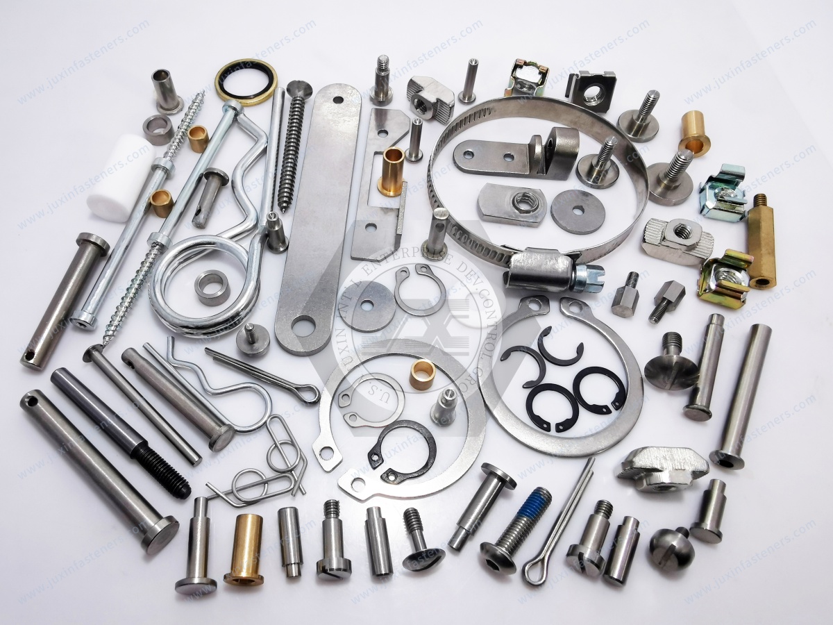
JUXIN FASTENERS can evaluate drawing-based custom shaft and CNC machined component projects for OEM and industrial applications.
Relevant product categories include:
Precision shafts
Stepped shafts
Threaded shafts
Spline shafts
Gear shafts
Drive shafts
Transmission shafts
Motor shafts
Pump shafts
Precision pins
Custom CNC machined components
Drawing-based mechanical parts
Material options can be evaluated according to customer drawings and application requirements, including:
Carbon steel
Alloy steel
Stainless steel
Aluminum alloys
Titanium
Engineering plastics
For projects involving heat treatment, surface hardening, grinding, spline machining or other specialized secondary processes,
the required finished-component properties and acceptance criteria should be defined during technical review.
Diameter transitions create local stress concentration. Fillet geometry, surface condition and actual bending/torsional loading can strongly affect fatigue initiation.
Keyways reduce section area and introduce local stress concentration. Root geometry, surface finish, torque, bending and fatigue cycles should be reviewed.
Sometimes stronger material helps, but not if the root cause is geometry, misalignment, poor surface condition, improper heat treatment or overload.
4140 is a material family, not a guarantee of component reliability. Geometry, heat treatment, hardness, fatigue loading, surface condition and assembly remain important.
There is no universal radius. It depends on shaft geometry, stress, mating-component clearance and the complete design.
Not automatically. Higher hardness can improve wear resistance in appropriate applications, but shaft reliability also requires suitable toughness and fatigue performance.
Heating and cooling can redistribute residual stresses and produce nonuniform dimensional changes. Geometry, material and process conditions influence distortion.
Yes. Hardness does not establish geometry, fatigue strength, case depth, toughness, surface quality or alignment.
No. Design, overload, misalignment, bearing problems, assembly and operating changes can also cause failure.
First identify the failure mechanism. If failure is dominated by stress concentration, geometry improvement may be more effective than material substitution.
Provide the 2D drawing, 3D model if available, revision, material, heat treatment, hardness, case depth, tolerances, GD&T, surface requirements, application and annual volume.
A sample can support dimensional evaluation, but functional requirements, material specifications, heat treatment and drawings are strongly preferred for critical components.
No. Geometry, case depth, surface condition, heat-treatment route, runout, tolerances and functional requirements may also matter.
Heat treatment can materially affect hardness, toughness, distortion and surface properties. It is part of the finished component's manufacturing system.
For a drawing-based replacement project, failure information can help identify whether material, geometry,
heat treatment or another design requirement should be reviewed before quoting a direct replacement.
For technical and commercial review, provide:
2D drawing
3D model
Part number
Drawing revision
Application
Shaft type
Material standard
Material grade
Material condition
Overall dimensions
Critical diameters
Shoulder geometry
Fillet requirements
Keyway specification
Spline specification
Thread specification
Retaining-ring groove details
Torque
Bending load
Axial load
Shock load
Rotational speed
Duty cycle
Fatigue requirement
Heat treatment
Hardness
Effective case depth
Core hardness where applicable
Hardened areas
Areas excluded from hardening
Bearing fits
Seal-running surface requirements
Dimensional tolerances
GD&T
Straightness
Runout
Surface roughness
Grinding requirements
Surface treatment
Corrosion environment
Operating temperature
Lubrication
Inspection requirements
Functional testing
Material documentation
First-article requirements
PPAP or customer-specific documentation where applicable
Annual volume
Existing approved sample for second-source development
For a shaft failure investigation, also provide:
Failure photographs
Fracture location
Fracture orientation
Service hours or cycles
Operating speed
Actual load if known
Failure history
Material certificate
Heat-treatment information
Hardness results
Bearing condition
Coupling condition
Alignment information
Any recent supplier, design or process changes
This article should connect internally with existing JUXIN FASTENERS resources covering:
Precision Shaft Material Selection: Steel Grades, Heat Treatment and Failure Prevention
Custom CNC Machined Parts
Custom Precision Pins and Shaft Components
Retaining Rings and Shaft Groove Design
ISO Metric Thread Tolerance and Thread Inspection
Fastener Material Selection
Stainless Steel Material Selection
Titanium Fasteners and CNC Components
Fastener Surface Finish Selection
Hydrogen Embrittlement in High-Strength Steel Components
Automotive Fastening and Machined Component Solutions
Agricultural and Off-Highway Equipment Fastening Solutions
Industrial Machinery Fastening Solutions
Railway and Rolling Stock Fastening Solutions
Supplier Qualification and Second-Source Development
Use the existing indexed JUXIN FASTENERS URL when implementing each internal link.
The intended internal content path is:
Shaft Material Selection → Shaft Failure Mechanism → Stress Concentration → Heat Treatment → Precision Manufacturing → Inspection → Second-Source Qualification → RFQ
This keeps this article distinct from the broader Precision Shaft Material Selection page.
The most important lesson in industrial shaft engineering is simple:
Do not solve every shaft failure by buying stronger steel.
Start with:
Failure Location → Load → Geometry → Material → Heat Treatment → Surface → Manufacturing → Assembly → Environment
Remember:
Higher Strength ≠ Automatically Higher Shaft Reliability.
Static Strength ≠ Fatigue Performance.
Nominal Stress ≠ Local Peak Stress.
Alloy Steel ≠ Fatigue-Proof Shaft.
Correct Hardness ≠ Correct Finished Component.
Same Material + Same Hardness ≠ Same Shaft Performance.
Correct Nominal Diameter ≠ Correct Bearing Fit.
High Material Strength ≠ High-Speed Capability.
Failed Shaft ≠ Automatically Defective Shaft.
Same Dimensions ≠ Functional Equivalence.
For design engineers, this framework helps distinguish a material problem from a geometry, fatigue, heat-treatment or system problem.
For quality teams, it creates a more useful starting point for root-cause analysis.
For procurement and supplier-development teams,
it provides a stronger method for qualifying custom shaft manufacturers and second sources than comparing material, dimensions and unit price alone.
JUXIN FASTENERS supports OEM, Tier-1, Tier-2 and industrial manufacturers with drawing-based precision shafts, stepped shafts, threaded shafts,
spline shafts, gear shafts, transmission shafts, drive shafts, motor shafts, pump shafts, precision pins and custom CNC machined components.
For a new shaft, second-source project or replacement of a failed component, send your drawing, revision, material specification, heat treatment,
hardness, critical tolerances, GD&T, operating conditions and annual volume for technical review.
JUXIN FASTENERS
Email: info@juxinfasteners.com
Website: www.juxinfasteners.com
Contact Us
Tel.:
+86 020 8621 0320
+86 020 3121 6067
E-mail:
Technical Support:
Navigation
SEND INQUIREY



