
Call Us
+86 136 6007 9809
Call Us
+86 136 6007 9809

Aug. 12, 2026
What is the best material for a precision shaft?
There is no universal answer.
A shaft that performs reliably in a low-speed industrial gearbox may be unsuitable for a high-cycle servo mechanism, corrosive pump, heavy construction machine or precision positioning system.
The original design question should therefore not be:
"Which shaft material is strongest?"
It should be:
"Which combination of material, heat treatment, geometry, surface condition and manufacturing process provides the required performance for this shaft?"
Precision shafts can experience torsion, bending, cyclic fatigue, shock, wear, bearing contact and environmental exposure simultaneously.
For OEM design engineers, procurement managers and supplier-development teams, the correct selection path is:
Application → Load Spectrum → Geometry → Fatigue → Wear → Environment → Material → Heat Treatment → Machining
→ Surface Finish → Dimensional Stability → Validation → Supplier Qualification
This guide explains that process for custom precision shafts, stepped shafts, threaded shafts, spline shafts, gear shafts, drive shafts,
transmission shafts, motor shafts, pump shafts and CNC machined shaft components.
Select shaft material from the complete operating condition rather than tensile strength alone.
Evaluate:
Torque
Bending moment
Combined stress
Cyclic loading and fatigue
Shock and impact
Bearing and seal contact
Wear
Required surface hardness
Core toughness
Corrosion environment
Operating temperature
Shaft diameter and section changes
Heat-treatment response
Distortion risk
Machinability
Dimensional and geometric tolerances
Production volume
Total manufactured cost
The central engineering rule is:
Higher Material Strength ≠ Automatically Higher Shaft Reliability.
A stronger steel cannot compensate for a poorly designed shoulder, sharp keyway, incorrect heat treatment, excessive grinding damage or unsuitable bearing fit.
A shaft is not simply a cylindrical steel part.
Depending on the design, it may contain:
Bearing journals
Threads
Keyways
Splines
Retaining-ring grooves
Cross holes
Shoulders
Gear teeth
Sealing surfaces
Ground diameters
Each feature changes the local stress, manufacturing process or surface requirement.
This is why shaft engineering requires several interacting decisions:
Bulk Strength + Fatigue Strength + Surface Properties + Core Toughness + Geometry + Heat Treatment + Manufacturing Quality
Selecting only from a material strength table misses much of the actual failure risk.
Many shafts transmit torque, but torque may not be the governing failure mechanism.
A rotating shaft can experience:
Torque produces shear stress through the shaft.
Relevant in:
Drive shafts
Transmission shafts
Gearbox shafts
Motor shafts
Gears, pulleys, sprockets, couplings and external loads can create bending moments.
This is common in real machinery.
The shaft may therefore need to withstand simultaneous normal and shear stresses.
A rotating shaft under a stationary transverse load can experience repeated stress cycles.
Fatigue may become critical even when the nominal stress is well below the material's static tensile strength.
Construction machinery, agricultural equipment and heavy transmission systems may experience transient overloads or impact.
Therefore:
Static Strength ≠ Fatigue Performance.
And:
Peak Torque Rating ≠ Complete Shaft Design.
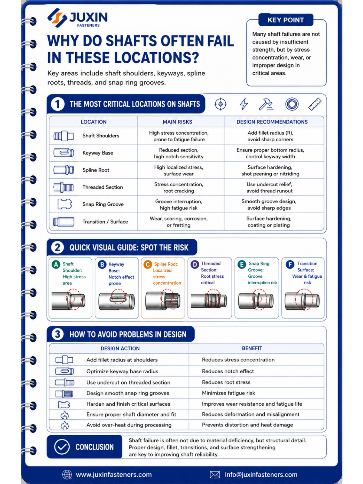
Shaft failures frequently initiate near geometric discontinuities rather than in a smooth constant-diameter section.
Critical locations include:
Shaft shoulders
Keyways
Spline roots
Relief grooves
Retaining-ring grooves
Thread run-outs
Cross holes
Diameter transitions
These features were correctly identified as critical stress-concentration locations in the original article.
The engineering implication is important:
Nominal Shaft Stress ≠ Local Peak Stress.
A shaft can therefore fail even though a basic calculation based on nominal diameter appears acceptable.
Consider a shaft with a diameter transition.
A sharp shoulder creates a local stress concentration.
Increasing material strength may improve nominal capacity, but redesigning the transition with an appropriate fillet may provide a more effective improvement in fatigue behavior.
Likewise, fatigue performance around a keyway depends on:
Keyway geometry
Root radius
Surface condition
Load direction
Material
Heat treatment
Residual stress
Therefore:
Stronger Steel ≠ Solution to Every Shaft Failure.
Sometimes the correct engineering action is a geometry change rather than a material upgrade.
A practical material-selection process can be divided into six engineering gates.
Define:
Torque
Bending
Axial load
Combined loading
Peak load
Shock load
Define:
Rotational speed
Load cycles
Load reversals
Duty cycle
Required service life
Determine whether the shaft requires:
Wear resistance
Bearing journal hardness
Gear/spline surface hardness
Seal-running surface control
Evaluate:
Humidity
Water
Chemicals
Salt/chloride
Lubricant
Temperature
Outdoor exposure
Consider:
Turning
Milling
Grinding
Spline machining
Threading
Heat treatment
Surface hardening
Straightening
Final inspection
Compare:
Raw material
Machining time
Heat treatment
Grinding
Inspection
Scrap risk
Distortion/rework
Production volume
Supply-chain availability
The optimal material must pass all six gates.
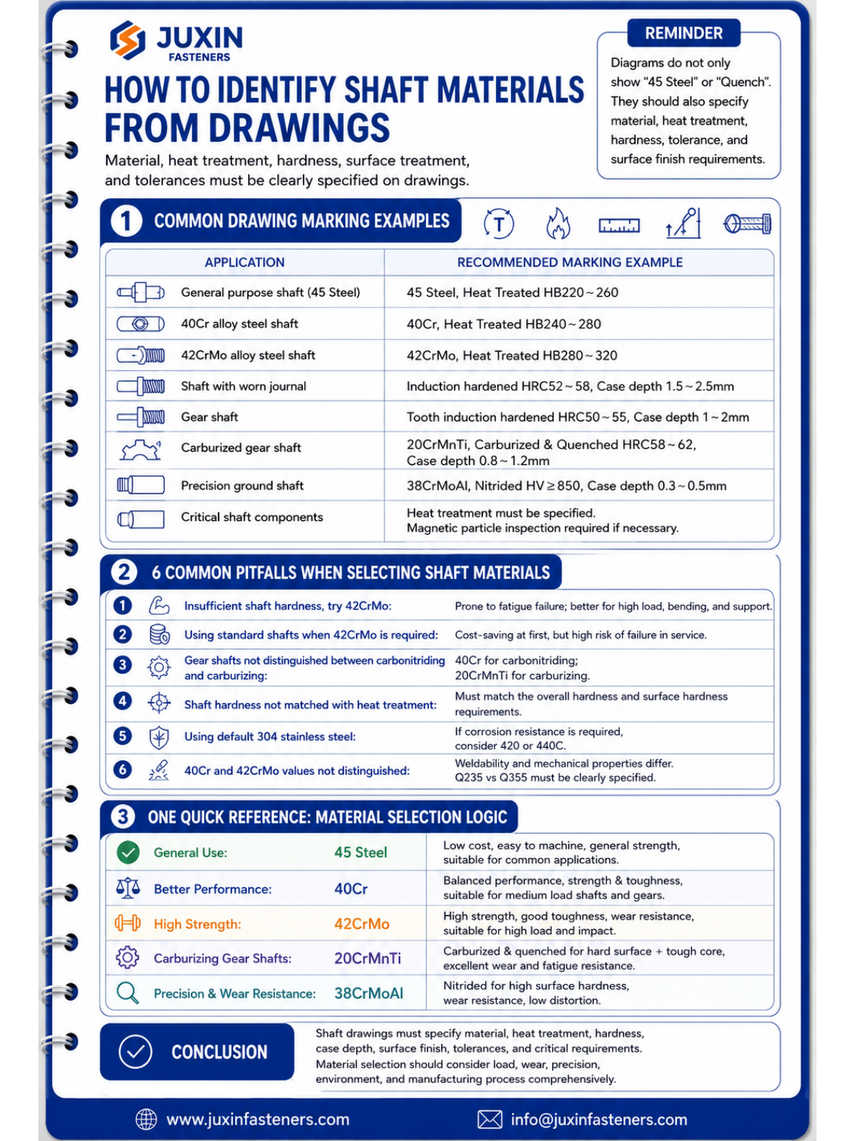
Medium-carbon steels such as AISI 1045 are widely considered for general-purpose shaft applications.
Potential applications include:
Conveyor shafts
Pump shafts
Motor shafts
General machinery shafts
Moderate-duty transmission components
Advantages can include:
Good machinability
Broad availability
Cost efficiency
Useful strength after appropriate processing
Suitability for selected surface-hardening processes
For many standard industrial applications, this material family can provide an effective balance between manufacturing cost and mechanical performance.
But:
Low Material Cost ≠ Lowest Finished Shaft Cost.
If the application requires extensive hardening, grinding, straightening and inspection, another material may provide better total manufacturing economics.
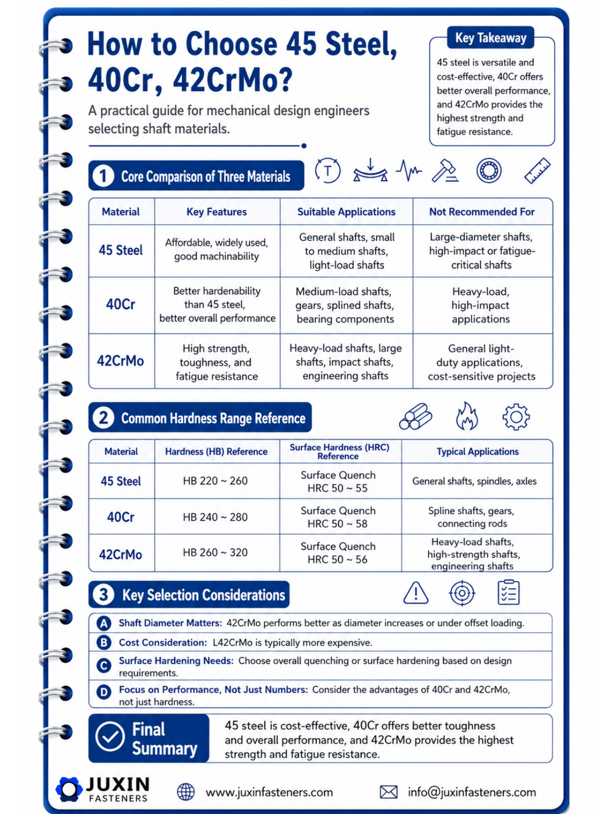
A medium-carbon steel may become less attractive when the application requires:
High section hardenability
High torque capacity
Severe shock loading
Demanding fatigue performance
Deep hardened properties
High core toughness
This is where alloy steels become relevant.
For higher-load precision shafts, chromium-molybdenum alloy steels are frequently evaluated because they can provide useful combinations of:
Strength
Hardenability
Toughness
Fatigue performance
Heat-treatment response
Internationally recognized grades should be specified directly on OEM drawings rather than relying on regional material shorthand.
Possible engineering families include materials specified through:
SAE/AISI
ASTM
EN
DIN/EN material designations
Customer-specific specifications
The exact grade should be selected from the required mechanical and heat-treatment properties.
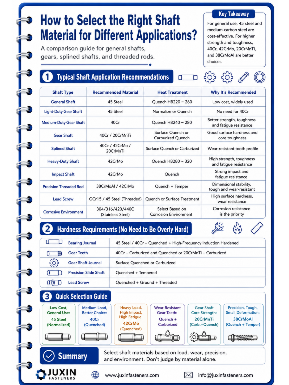
SAE 4140 and EN 42CrMo4-type chromium-molybdenum steels are widely considered for demanding mechanical components.
Potential shaft applications include:
Heavy transmission shafts
Gearbox shafts
Construction equipment shafts
Hydraulic machinery components
Industrial drive systems
Spline shafts
Potential advantages include:
Good hardenability
High strength after appropriate heat treatment
Useful toughness
Suitability for demanding cyclic loads
However:
4140/42CrMo4 Material Name ≠ Finished Shaft Performance.
Final properties depend on:
Material condition
Section size
Heat treatment
Hardness
Microstructure
Machining
Surface condition
The drawing should define the finished-component requirements.
One major improvement over older shaft-selection articles is to avoid presenting regional grades as if they have automatic one-to-one international equivalents.
Material equivalence should compare:
Chemical composition
Mechanical properties
Heat-treatment condition
Hardenability
Product form
Applicable material standard
Therefore:
Similar Chemistry ≠ Automatic Material Equivalence.
For OEM sourcing, specify the recognized grade and governing material standard required by the design.
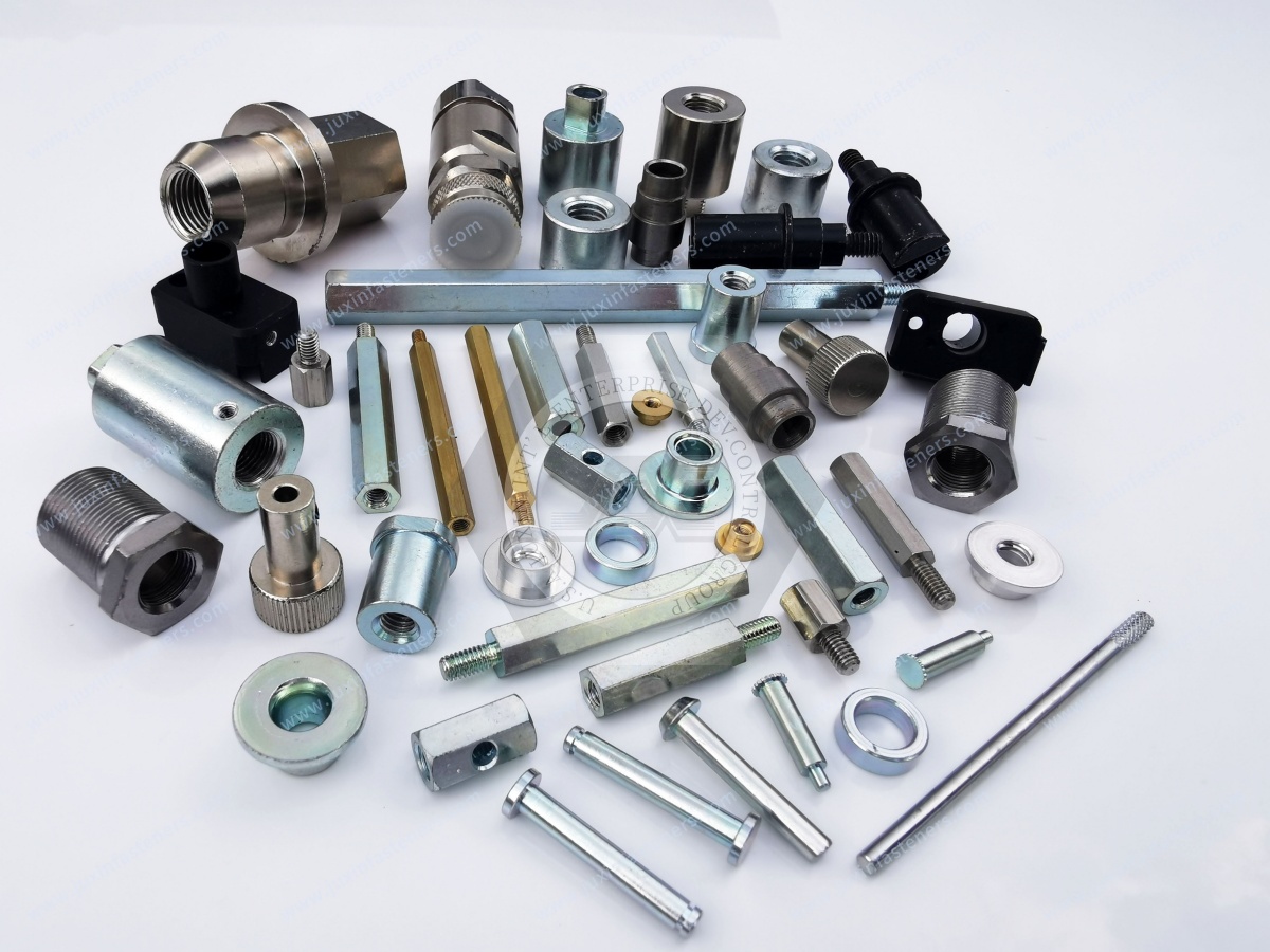
Some shafts require:
Hard Surface + Tough Core
Examples can include:
Gear shafts
Transmission components
Wear-intensive spline systems
In these applications, carburizing steels may be considered.
The goal is to create a wear-resistant case while maintaining a tougher core.
But carburizing introduces additional design considerations:
Case depth
Surface hardness
Core hardness
Distortion
Grinding allowance
Retained dimensional accuracy
Therefore:
Carburized ≠ Complete Heat-Treatment Specification.
Nitriding may be considered where engineers require a hardened surface with controlled dimensional behavior.
Potential applications include:
Precision shafts
Wear surfaces
Lead-screw components
Machine-tool components
Selected automation equipment
A nitriding specification should define more than the process name.
Depending on the project, it may need:
Base material
Surface hardness
Effective case depth
Nitrided areas
Areas to be protected
Post-treatment requirements
Again:
Nitriding Process Name ≠ Finished Component Specification.
Stainless steel becomes relevant when corrosion resistance is a significant design requirement.
Possible applications include:
Food-service equipment
Medical equipment
Pumps
Chemical equipment
Outdoor machinery
Marine-adjacent equipment
Clean industrial environments
Common engineering questions include whether to select an austenitic or precipitation-hardening stainless grade.
The answer depends on:
Required strength
Corrosion environment
Chlorides
Chemicals
Temperature
Wear
Machinability
Heat treatment
And:
Stainless Steel ≠ Corrosion-Proof Shaft.
304 and 316 stainless steels are commonly considered for corrosion-resistant components.
316 can provide improved resistance in some chloride-containing and chemical environments.
But:
316 ≠ Automatically Better Shaft Material.
A shaft may require mechanical strength, wear resistance or hardness that changes the material decision.
Environmental performance must be balanced against mechanical requirements.
Where corrosion resistance and higher mechanical strength are both important, precipitation-hardening stainless steels may be considered.
The actual grade and heat-treatment condition should be defined by the application and drawing.
Do not approve a replacement based only on the words:
"Stainless shaft."
Aluminum alloys can be considered where low mass is important.
Potential applications include:
Lightweight mechanisms
Automation
Instrumentation
Selected positioning equipment
But aluminum shaft design must consider:
Lower elastic modulus
Surface wear
Bearing interfaces
Thread strength
Fatigue
Surface treatment
Galvanic interaction
Therefore:
Lower Weight ≠ Direct Steel Replacement.
A steel-to-aluminum shaft conversion normally requires engineering review.
Titanium alloys such as Ti-6Al-4V may be considered where combinations of:
Low density
High specific strength
Corrosion resistance
are valuable.
Potential applications can include specialized:
Aerospace equipment
Medical equipment
High-performance machinery
Corrosive environments
But titanium brings different considerations:
Material cost
Machining
Galling
Surface wear
Bearing interfaces
A titanium shaft should be selected because the application benefits from its properties—not simply because it is a premium material.
Materials such as:
PEEK
POM / Acetal
PTFE
Other engineering polymers
may be considered for selected low-load, chemically resistant, electrically isolating or specialized mechanical applications.
But:
Plastic Shaft ≠ Metal Shaft With Lower Weight.
Engineers must consider:
Creep
Temperature
Moisture
Chemical compatibility
Wear
Thermal expansion
Dimensional stability
Polymer grade is also critical.
Same Polymer Name ≠ Same Finished Performance.
| Material Family | Typical Engineering Advantage | Key Design Question |
|---|---|---|
| Medium-carbon steel | Cost/performance balance | Is hardenability sufficient for the section and load? |
| Cr-Mo alloy steel | Strength, toughness, hardenability | What final hardness and heat treatment are required? |
| Case-hardening steel | Hard surface with tough core | What case depth and distortion control are required? |
| Nitriding steel | Wear-resistant surface with controlled distortion | What nitrided depth and hardness are required? |
| Austenitic stainless steel | Corrosion resistance | Are strength and wear performance sufficient? |
| PH stainless steel | Strength plus corrosion resistance | What heat-treatment condition is required? |
| Aluminum alloy | Low mass | Can stiffness, wear and fatigue requirements be met? |
| Titanium alloy | High specific strength and corrosion resistance | Do application benefits justify machining and material cost? |
| Engineering plastic | Chemical/electrical/specialized functions | Are creep, temperature and dimensional stability acceptable? |
The purpose of this table is not to choose a material automatically.
It is to identify the next engineering question.
The original article correctly recognized heat treatment as a major part of shaft design and listed processes including quenching and tempering,
induction hardening, carburizing, nitriding and stress relieving.
A more complete engineering principle is:
Material Grade + Heat Treatment + Geometry + Surface Condition = Finished Shaft Performance
Two shafts made from the same alloy can perform very differently after different heat treatments.
Quenching and tempering may be used to develop a balance of:
Strength
Hardness
Toughness
For shafts, drawings should define the required finished condition rather than simply state:
Q&T
Possible requirements include:
Hardness range
Mechanical properties
Heat-treated condition
Test location where relevant
Induction hardening can selectively harden areas such as:
Bearing journals
Wear surfaces
Spline regions
while maintaining different properties in the core or other regions.
Important specification variables include:
Hardened location
Surface hardness
Effective case depth
Transition area
Distortion control
Induction Hardened ≠ Complete Specification.
Carburizing is useful where the shaft requires:
Wear-resistant surface
Fatigue-resistant case
Tougher core
But deep case requirements can affect:
Cycle time
Cost
Distortion
Grinding allowance
The process should therefore be selected together with the geometry and final tolerance strategy.
Nitriding can provide surface hardness and wear resistance with different thermal/distortion characteristics from conventional quench hardening.
But the base material must be suitable for the intended process and result.
Stress relieving may be useful during multi-stage machining of precision components where residual stress could contribute to dimensional movement.
This becomes increasingly important when a shaft requires:
Long slender geometry
Tight runout
Multiple diameter steps
Grinding after heat treatment
A shaft may meet its mechanical-property target after heat treatment and still fail dimensional inspection.
Potential distortion includes:
Bow
Runout change
Diameter change
Taper
Feature movement
This creates an important manufacturing principle:
Correct Hardness ≠ Correct Finished Shaft.
The production route must anticipate dimensional change.
Depending on the design, the manufacturing sequence may include:
Rough Machining → Heat Treatment → Straightening if Required → Finish Machining/Grinding → Final Inspection
This allows critical dimensions and geometric tolerances to be controlled in the final condition.
The exact process depends on the material and shaft design.
A bearing journal requires more than the correct diameter.
Depending on the bearing system, engineers may need to control:
Diameter tolerance
Roundness
Cylindricity
Surface roughness
Runout
Hardness
A shaft can be dimensionally "within diameter tolerance" while still causing bearing problems because of geometric error.
Therefore:
Correct Diameter ≠ Correct Bearing Journal.
Where a shaft passes through a rotary or reciprocating seal, the surface can influence:
Leakage
Seal wear
Friction
Service life
The drawing should define the surface requirement appropriate to the seal system.
Again:
Ra Value Alone ≠ Complete Surface Specification.
Surface texture, process and directionality may matter depending on the application.
Long or precision shafts may require control of:
Straightness
Total runout
Circular runout
Coaxiality-related geometry
These characteristics influence:
Bearing life
Vibration
Seal behavior
Gear alignment
Rotational stability
For high-speed systems, geometry can become as important as material strength.
High-speed shaft design may need to consider:
Rotational balance
Runout
Stiffness
Critical speed
Bearing arrangement
Mass distribution
Surface condition
Therefore:
High Strength ≠ High-Speed Capability.
The entire rotating system must be evaluated.
Spline shafts introduce additional engineering requirements because torque is transferred through multiple teeth.
Important variables can include:
Spline standard
Tooth geometry
Fit
Alignment
Surface hardness
Root stress
Wear
Material selection should therefore be coordinated with spline geometry and heat treatment.
Threads create another stress concentration and interface.
Design considerations include:
Thread standard
Thread tolerance
Thread run-out
Surface treatment
Root stress
Assembly method
The thread should not be treated independently from the shaft's fatigue design.
Gear shafts combine:
Shaft bending
Torque
Gear-tooth contact
Gear-root stress
Bearing alignment
This may require a material and heat-treatment strategy that satisfies both the gear and shaft functions.
Therefore:
Good Shaft Material ≠ Automatically Good Gear Material.
The complete component should be designed as one system.
Motor and servo applications may prioritize:
Runout
Concentricity
Surface finish
Dimensional stability
Repeatability
In precision motion systems, simply upgrading to a higher-strength alloy may provide little benefit if the actual problem is runout or thermal dimensional change.
Pump shafts can combine mechanical loading with:
Water
Chemicals
Corrosion
Seal interfaces
Material selection may therefore be driven by corrosion compatibility as much as strength.
A corrosion-resistant shaft still requires proper mechanical design.
Corrosion Resistance ≠ Fatigue Qualification.
Agricultural and off-highway shaft components can encounter:
Shock
Dirt
Moisture
Variable loading
Wear
Outdoor corrosion
Relevant products may include:
Drive shafts
Transmission shafts
Pins
Machined bolts
Custom CNC components
The material decision should balance toughness, fatigue, wear and corrosion protection.
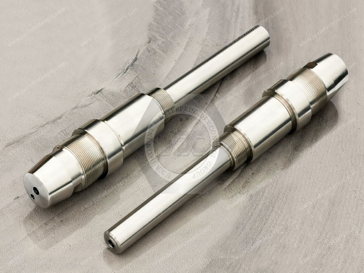
Heavy equipment can impose:
High torque
Impact
Cyclic loading
Abrasive contamination
High-strength alloy steel may be appropriate, but geometry and heat treatment remain critical.
Automotive shaft components can require combinations of:
High-volume consistency
Fatigue performance
Dimensional control
Heat-treatment repeatability
Surface engineering
Traceability
But:
Material Grade ≠ Automotive Qualification.
OEM and Tier-1 customer specifications remain controlling requirements.
Custom shafts, pins and machined components may be used in selected rail equipment and rolling-stock systems.
However, rail applications must distinguish between:
Non-structural equipment
Secondary/supporting components
Primary structural or safety-critical components
Running gear, braking, bogie, crash or other safety-critical systems require formal project/OEM specifications and application validation.
Machined Component Capability ≠ Safety-Critical Rail Qualification.
The original article correctly noted that a professional shaft drawing should specify more than material and should include heat treatment,
hardness, surface requirements, dimensional tolerances and geometric tolerances.
A stronger OEM shaft specification may include:
Part number
Revision
Material standard
Material grade
Initial material condition
Heat treatment
Hardness
Case depth if applicable
Hardened zones
Areas protected from hardening
Dimensional tolerances
Geometric tolerances
Bearing fits
Spline specification
Thread specification
Surface roughness
Coating or corrosion protection
Deburring requirements
Edge conditions
Inspection requirements
Functional requirements
This greatly reduces supplier interpretation.
A drawing note such as:
HARDENED
is incomplete.
The supplier still needs to know:
Which area?
Which process?
What hardness?
What depth?
What core requirement?
What final dimensional condition?
Similarly:
Heat Treated
is not a finished engineering specification.
| Failure | Possible Root Cause | Engineering Review |
|---|---|---|
| Fatigue fracture at shoulder | Stress concentration, inadequate radius, surface defect | Review geometry, load spectrum and surface condition |
| Fracture at keyway | Local stress concentration and cyclic loading | Review keyway geometry, material and heat treatment |
| Twisted shaft | Torsional overload or insufficient section strength | Review torque and shaft diameter |
| Bent shaft | Overload, inadequate stiffness or heat-treatment distortion | Review load, geometry and manufacturing route |
| Bearing journal wear | Inadequate hardness, finish or lubrication | Review journal specification |
| Spline wear | Fit, hardness, alignment or lubrication problem | Review complete spline system |
| Corrosion damage | Material/environment mismatch | Review material and protection |
| Cracking after heat treatment | Material/process/geometry interaction | Review heat-treatment route |
| Excessive runout | Machining, heat treatment or straightness issue | Review process sequence and inspection |
| Thread-runout fatigue crack | Geometry and cyclic stress | Review thread termination and local stress |
This failure-mode approach is more useful than automatically upgrading to a stronger steel.
Suppose a shaft repeatedly fails at a shoulder.
Option A:
Change from medium-carbon steel to a stronger alloy.
Option B:
Improve:
Shoulder radius
Surface finish
Transition geometry
Heat treatment
The stronger material may help.
But if the failure is dominated by a severe local stress concentration, geometry improvement may provide the more effective solution.
This leads to an important decision rule:
Before Changing Material, Identify Where and Why the Shaft Fails.
Procurement teams should not approve a second source by comparing only:
Material
Overall dimensions
Unit price
Two shafts can have identical dimensions and nominal material but perform differently.
A robust comparison is:
Drawing + Revision + Material Standard + Material Grade + Mechanical Properties + Heat Treatment + Hardness + Case Depth + Geometry
+ Surface Finish + Dimensional Tolerances + GD&T + Threads/Splines + Coating + Functional Testing + Documentation + Change Control
Therefore:
Same Dimensions ≠ Functional Equivalence.
And:
Same Material Name ≠ Same Finished Shaft.
A second-source shaft may match the specified HRC value.
That still does not prove complete equivalence.
Hardness does not independently define:
Toughness
Case depth
Core properties
Microstructure
Fatigue performance
Dimensional accuracy
Therefore:
Same Hardness ≠ Same Shaft Performance.
For an OEM shaft supplier, evaluate more than machining capacity.
Relevant questions include:
Can the supplier interpret GD&T?
Can material be controlled to the required specification?
Is heat treatment defined and controlled?
Can post-heat-treatment distortion be managed?
Can critical journals be ground to final tolerance?
Can spline/thread features be controlled?
How are hardness and case depth verified when required?
How are critical dimensions inspected?
How are drawing revisions controlled?
How are material or process changes managed?
Can first-article or customer-specific documentation be supported when required?
This is particularly important for high-volume or function-critical parts.
A shaft's purchase price may be only one part of its real cost.
Consider:
Total Installed Cost = Part Price + Machining + Heat Treatment + Grinding + Inspection + Assembly + Rework + Scrap + Downtime + Warranty Risk + Logistics + Supply Risk
A low-cost shaft that creates:
Bearing failures
Excessive runout
Premature wear
Assembly problems
Field failures
can become substantially more expensive than a correctly engineered component.
Therefore:
Lowest Part Price ≠ Lowest Installed Cost.
Design engineers searching for shaft material guidance commonly need answers to questions such as:
What material should I use for a drive shaft?
Which steel is best for a spline shaft?
Should a shaft be carburized or nitrided?
How should a bearing journal be hardened?
Why did my shaft break at the shoulder?
How do I improve shaft fatigue life?
Should I use stainless steel for a pump shaft?
How does heat treatment affect shaft distortion?
A useful supplier page should help answer these decisions before asking for an RFQ.
Procurement teams may search:
Custom shaft manufacturer
Precision CNC shaft supplier
OEM transmission shaft supplier
Custom spline shaft manufacturer
CNC machined shaft supplier
Second-source shaft manufacturer
Stainless steel shaft supplier
Custom threaded shaft manufacturer
Precision machined components supplier
For these searches, procurement needs more than a product list.
They need evidence that the supplier understands:
Material → Heat Treatment → Machining → Grinding → Inspection → Functional Requirement
JUXIN FASTENERS can evaluate drawing-based custom precision shafts and CNC machined components for OEM and industrial applications.
The existing product scope includes custom shaft categories such as precision shafts, stepped shafts, threaded shafts, gear shafts, drive shafts,
transmission shafts, spline shafts, motor shafts, pump shafts and other OEM machined components.
Project requirements may involve:
Carbon steel
Alloy steel
Stainless steel
Aluminum
Titanium
Engineering plastics
The actual material and manufacturing route should be selected from the drawing and application rather than assumed from the shaft name.
For projects requiring specialized operations such as heat treatment, grinding, spline generation or other secondary processes,
the required process and finished-component acceptance criteria should be clearly defined during RFQ review.
There is no universal best steel. The correct choice depends on torque, bending, fatigue, impact, wear, corrosion, heat treatment, shaft size and manufacturing requirements.
AISI 1045-type medium-carbon steel can be suitable for many general industrial shafts where its mechanical properties and heat-treatment response satisfy the design.
Cr-Mo alloy steels may be considered for higher-load applications requiring improved strength, toughness and hardenability.
Final selection must account for section size, heat treatment and required mechanical properties.
No. Higher strength can increase cost and manufacturing complexity and cannot correct poor geometry, incorrect heat treatment or surface defects.
Diameter transitions create stress concentration. Fillet radius, surface finish, load spectrum and local geometry can strongly influence fatigue initiation.
Only where the application requires it. Wear surfaces, bearing journals, splines or gear features may benefit from specific hardening processes, but the required process depends on the design.
Neither is universally better. They produce different surface and manufacturing characteristics and should be selected from material, case-depth, hardness, distortion and application requirements.
Residual stress and nonuniform dimensional changes during heating and cooling can cause distortion. Material, geometry and process route must be considered.
Not automatically. Corrosion resistance may improve while strength, hardness, wear and fatigue characteristics change.
No. Hardness is only one material property and does not independently establish toughness, fatigue performance, case depth or dimensional quality.
Send the complete drawing, 3D model if available, material, heat treatment, hardness, tolerances, GD&T, surface finish, coating, application and annual volume.
A sample can support reverse-engineering or second-source evaluation, but drawings and functional requirements are strongly preferred for critical components.
Not automatically. Heat treatment, hardness, geometry, surface condition, process route and functional performance should also be compared.
Material substitutions affecting mechanical or functional performance should normally receive appropriate engineering approval.
They work together. The correct material with the wrong heat treatment can fail, while a suitable material/process combination can provide reliable performance.
JUXIN FASTENERS can evaluate custom precision shafts and CNC machined components based on customer drawings, specifications, material, tolerances and application requirements.
For faster engineering and commercial evaluation, provide:
2D drawing
3D model
Part number
Drawing revision
Application
Shaft type
Material standard
Material grade
Material condition
Shaft length
Critical diameters
Torque requirement
Bending load
Axial load
Peak load
Fatigue requirement
Rotational speed
Duty cycle
Heat treatment
Hardness
Case depth
Hardened areas
Core hardness where required
Bearing journal tolerances
Seal-running surface requirements
Spline specification
Keyway specification
Thread specification
Dimensional tolerances
GD&T requirements
Straightness
Runout
Surface roughness
Grinding requirements
Surface treatment
Corrosion environment
Operating temperature
Lubrication
Inspection requirements
Functional testing
Material documentation
First-article requirements
PPAP or customer-specific documentation where applicable
Annual volume
Existing approved sample for second-source projects
For a failed shaft investigation, also provide:
Failure photographs
Fracture location
Service hours/cycles
Actual operating load
Material certificate if available
Hardness results
Heat-treatment record
Failed-component dimensions
This information allows the root cause to be evaluated before simply increasing material strength.
This page should connect internally with existing JUXIN FASTENERS resources covering:
Custom CNC machined parts
Stainless steel fastener and component material selection
Titanium fasteners and machined components
Fastener material selection
Thread tolerance and 6H/6g thread fit
Fastener surface finish selection
Zinc plating and zinc-nickel engineering
Hydrogen embrittlement in high-strength steel components
Retaining rings and shaft grooves
Custom pins and precision machined pins
Automotive fastening and machined-component solutions
Agricultural and off-highway equipment fastening solutions
Railway and rolling-stock fastening solutions
Industrial machinery fastening solutions
Supplier qualification and second-source development
Use the existing indexed JUXIN FASTENERS URL when implementing each internal link.
The intended internal content path is:
Shaft Application → Load & Fatigue → Material → Heat Treatment → Geometry → Machining → Surface & Tolerance → Failure Prevention → Supplier Qualification → RFQ
Reliable shaft design does not come from choosing the strongest material in a table.
It comes from matching:
Load + Fatigue + Geometry + Material + Heat Treatment + Surface + Manufacturing + Dimensional Control
Remember:
Higher Strength ≠ Automatically Better Shaft.
Static Strength ≠ Fatigue Performance.
Nominal Stress ≠ Local Peak Stress.
Same Material Name ≠ Same Finished Shaft.
Same Hardness ≠ Same Shaft Performance.
Correct Hardness ≠ Correct Finished Shaft.
Correct Diameter ≠ Correct Bearing Journal.
Corrosion Resistance ≠ Fatigue Qualification.
Same Dimensions ≠ Functional Equivalence.
For design engineers, this framework helps prevent material selection from becoming a substitute for actual shaft engineering.
For procurement and supplier-development teams, it creates a better basis for comparing custom shaft manufacturers and qualifying second sources.
For quality teams, it provides a structured path for separating material problems from geometry, heat-treatment, machining and dimensional-control problems.
JUXIN FASTENERS supports OEM, Tier-1, Tier-2 and industrial manufacturers with drawing-based custom precision shafts, stepped shafts, threaded shafts,
spline shafts, transmission shafts, drive shafts, motor shafts, pump shafts, CNC machined parts and custom mechanical components.
For a new custom shaft, second-source project or shaft failure investigation, send your drawing, revision, material requirement, heat treatment, hardness,
critical tolerances, GD&T, application conditions and annual volume for technical review.
JUXIN FASTENERS
Email: info@juxinfasteners.com
Website: www.juxinfasteners.com
Contact Us
Tel.:
+86 020 8621 0320
+86 020 3121 6067
E-mail:
Technical Support:
Navigation
SEND INQUIREY



