
Call Us
+86 136 6007 9809
Call Us
+86 136 6007 9809

Sep. 21, 2026
In industrial sheet-metal fabrication, equipment enclosure manufacturing and modular chassis assembly, selecting the fastener is only one part of the engineering problem.
The larger challenge is creating a fastening specification that can move reliably from:
Design → Prototype → Supplier RFQ → Sample Approval → Production → Multiple Manufacturing Plants → Replacement Supply
without losing critical information.
For strategic sourcing managers, procurement teams, supply-chain managers and design engineers, clip-on nuts for sheet metal fabrication represent an important family of edge-mounted fastening solutions.
These products can include:
U-nuts;
J-nuts;
strong-grip clip-on nuts;
barrel clip-on nuts;
enclosed hex clip-on nuts;
low-profile clip-on nuts;
machine-screw spring nuts;
tapping-screw spring clips;
drawing-specific spring fasteners.
They can provide captive threaded or screw-engagement points on suitable sheet-metal edges without requiring a conventional loose nut behind the panel.
However, successful OEM sourcing requires much more than sending a supplier:
“M6 clip nut — please quote.”
A production-ready sourcing specification should control the complete interface:
Clip Geometry + Panel Geometry + Hole Position + Thread / Screw + Material + Surface System + Assembly Method + Functional Requirement + Production Tolerance
This guide explains how engineering and procurement teams can convert a generic clip-nut requirement into a controlled global OEM sourcing package.
Modern sheet-metal products are built through combinations of:
laser cutting;
punching;
stamping;
bending;
forming;
welding;
coating;
final assembly.
Every fastening method changes this manufacturing sequence.
Clip-on nuts can be attractive because they can create a threaded or screw-engagement point without requiring a welded nut or a loose backside nut.
In appropriate applications, they can also support installation after painting or powder coating.
Their real value, however, depends on the entire manufacturing architecture.
Clip-on nuts can provide several manufacturing advantages when correctly applied.
Where the design permits, clip-on nuts can be installed after:
painting;
powder coating;
selected surface-finishing operations.
This can reduce some manufacturing complications associated with threaded features installed before finishing.
However, post-finish installation is not automatically damage-free.
The clip geometry, panel finish and installation method must be compatible.
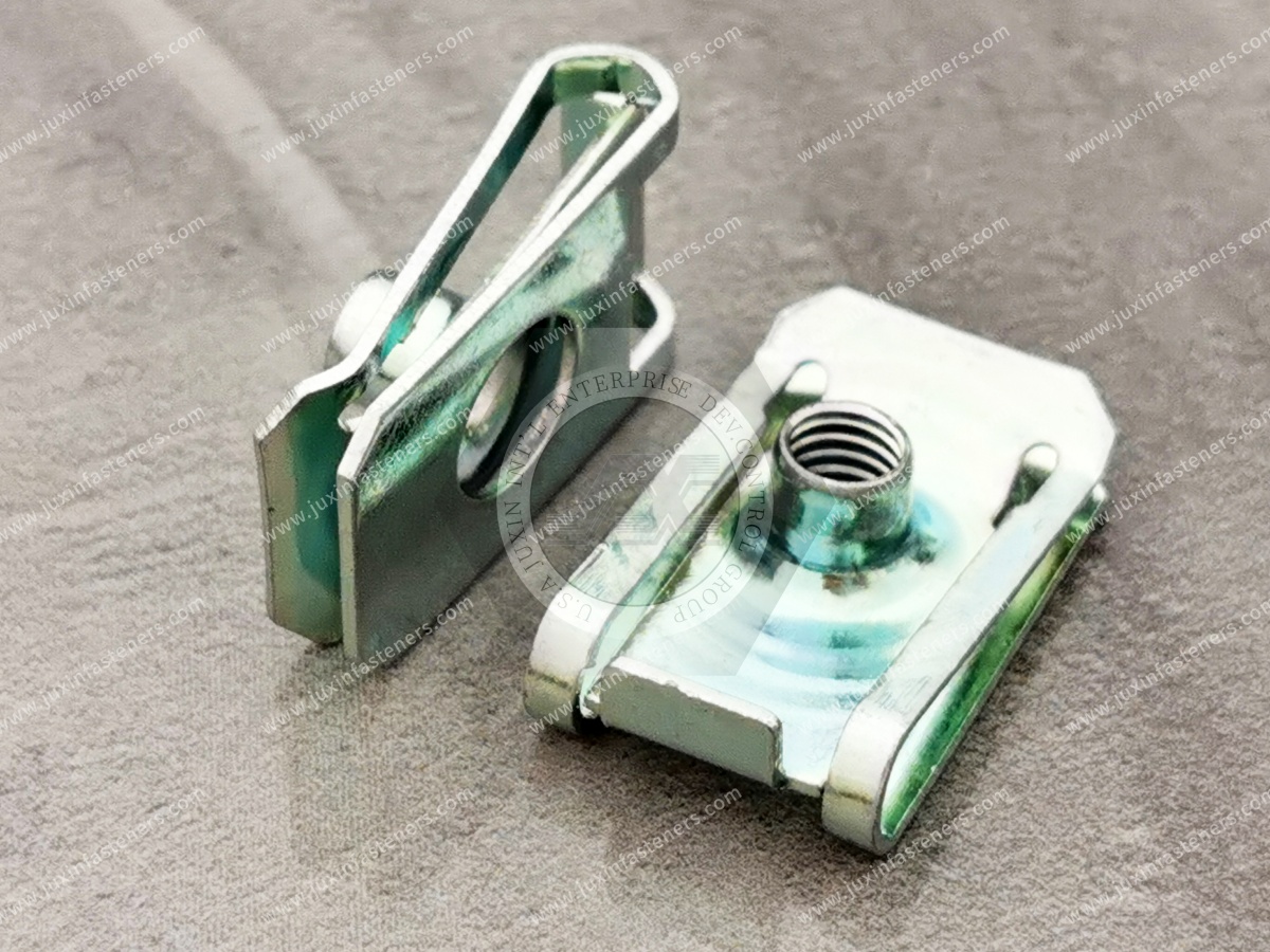
Clip-on nuts do not require welding at their installation location.
This can be useful where manufacturers want to avoid:
local welding operations;
weld distortion;
weld-related process steps;
post-weld finishing issues.
This does not mean welding is inherently inferior.
Weld nuts remain appropriate for many high-volume and permanent fastening architectures.
Once properly installed, the clip retains the threaded element at the panel edge.
This can simplify assembly where holding a separate nut behind the panel would be difficult.
Some clip-on nuts can be removed and replaced if damaged.
This can be useful in serviceable equipment.
Replaceability, however, does not mean unlimited reuse.
A sourcing program should first determine whether a clip-on nut is actually the correct fastener architecture.
Alternatives can include:
weld nuts;
self-clinching nuts;
blind rivet nuts;
cage nuts;
tapped features;
threaded inserts;
loose nuts.
Each architecture solves a different combination of:
access;
panel geometry;
load;
manufacturing sequence;
serviceability;
cost.
For a broader comparison, see Sheet-Metal Fastener Selection Guide.
Clip-on nuts generally depend on access to a suitable panel edge.
Therefore, the first geometry question should be:
Can the fastener be installed from the panel edge?
If yes, a clip-on architecture may be a candidate.
If the required threaded point is far from the edge and only one side is accessible, another fastening architecture may be more suitable.
This distinction prevents a common sourcing mistake:
Blind Screw Access ≠ Clip Installation Without Edge Access
U-nuts and J-nuts are not simply two names for the same geometry.
Their shapes can influence:
installation direction;
panel engagement;
throat depth;
clearance;
retention behavior.
For detailed geometry selection, see U-Nuts vs J-Nuts Geometry.
Barrel-style clip-on nuts can provide a compact threaded architecture for selected sheet-metal assemblies.
Important parameters can include:
panel thickness;
throat depth;
hole position;
barrel/thread geometry;
available envelope.
For related product selection, see Strong-Grip Clip-On Barrel Nuts & U-Nuts.
Enclosed hex designs can provide a captive nut element within a spring clip architecture.
They can be useful where a more conventional nut-style threaded element is desired.
They should not automatically be interpreted as:
sealed;
waterproof;
vibration-proof;
structurally superior.
For additional engineering guidance, see Strong-Grip Clip-On Enclosed Hex Nuts.
Folded flanges create specific geometry constraints.
Selection can depend on:
flange thickness;
flange width;
bend radius;
hole setback;
nearby return geometry.
For more detail, see Clip-On Nuts for Flanged Edges.
Some spring clips are designed for tapping-screw engagement rather than a conventional machine-screw nut thread.
These should not be sourced interchangeably with machine-thread clip-on nuts.
The mating screw system is part of the fastener specification.
Low-profile designs can help where packaging space is restricted.
However:
Low Profile ≠ Higher Strength
and:
Low Profile ≠ Automatically Better Assembly
A very compact clip can create tighter:
alignment;
installation;
driver-access
requirements.
One of the most common sourcing errors is defining the component only by thread size.
For example:
M6 U-Nut
is not a complete specification.
Two M6 U-nuts can differ in:
panel grip range;
material thickness;
overall width;
throat depth;
hole setback;
spring-arm geometry;
thread construction;
free-state geometry;
finish;
installation behavior.
Therefore:
Same Thread Size ≠ Interchangeable Clip Nut
A reliable clip-on nut specification should begin with the sheet-metal interface rather than the supplier catalogue.
The engineering sequence should be:
Panel → Edge Geometry → Hole → Clip → Thread → Screw → Joint
This is more robust than:
Catalogue Part → Try to Make Panel Fit
Identify the panel material.
Examples may include:
carbon steel sheet;
stainless steel sheet;
aluminum sheet;
another specified sheet material.
Panel material can affect:
local deformation;
clip grip;
surface interaction;
corrosion interface.
Nominal sheet thickness alone is not enough.
Engineering should consider:
nominal thickness;
production tolerance;
finished thickness where relevant.
For detailed selection guidance, see Panel Thickness Selection Guide.
The clip must operate within an appropriate panel-thickness range.
If the panel is too thin relative to the clip geometry, the fastener may have inadequate retention.
If the panel is too thick, installation can produce excessive spring deflection.
Therefore:
Nominal Panel Thickness ≠ Complete Grip Specification
Paint and powder coating can change the effective panel interface.
For post-finish clip installation, consider:
Base Sheet + Surface Finish + Production Variation
The coating may also influence:
insertion force;
friction;
local marking;
clip retention.
A clip installed after finishing can still scratch or compress a coating.
If finish appearance or corrosion protection is critical, evaluate:
clip edge geometry;
installation force;
coating hardness;
coating thickness;
installation method.
Therefore:
Post-Paint Installation ≠ Zero Finish Damage by Definition
Hole diameter should be controlled according to the selected fastener and mating screw system.
A generic “standard clearance hole” should not be assumed.
Different clip designs may use different:
hole geometry;
thread alignment;
screw entry conditions.
Hole setback is the distance from the panel edge to the hole center.
This dimension is fundamental to clip selection.
Incorrect setback can cause:
misalignment;
cross-threading;
clip migration;
abnormal screw starting;
assembly difficulty.
Throat depth determines how far the functional thread position lies from the panel edge.
It should be controlled separately from thread size.
Therefore:
M5 / M6 / 1/4-20 ≠ Throat Depth
A narrow flange may limit:
clip installation;
clip seating;
available edge distance;
tool access.
Flange geometry belongs in the RFQ.
The nearby bend radius can interfere with clip seating.
A clip that fits a flat coupon may not seat correctly beside a formed bend.
This is one reason why sample testing on production-intent sheet metal is valuable.
Sheet-metal assemblies contain multiple dimensional variations.
These may include:
sheet thickness;
hole position;
bend location;
flange angle;
coating thickness;
mating-part position.
The fastener should be selected against the actual tolerance stack rather than nominal CAD geometry alone.
A common assumption is that clip-on nuts automatically provide floating alignment.
That is not correct.
Some geometries may permit limited positional accommodation.
Others locate the threaded element much more rigidly.
Therefore:
Clip-On Nut ≠ Automatically Floating Nut
If float is required, define:
required direction;
required movement;
alignment tolerance.
Do not assume it from the product name.
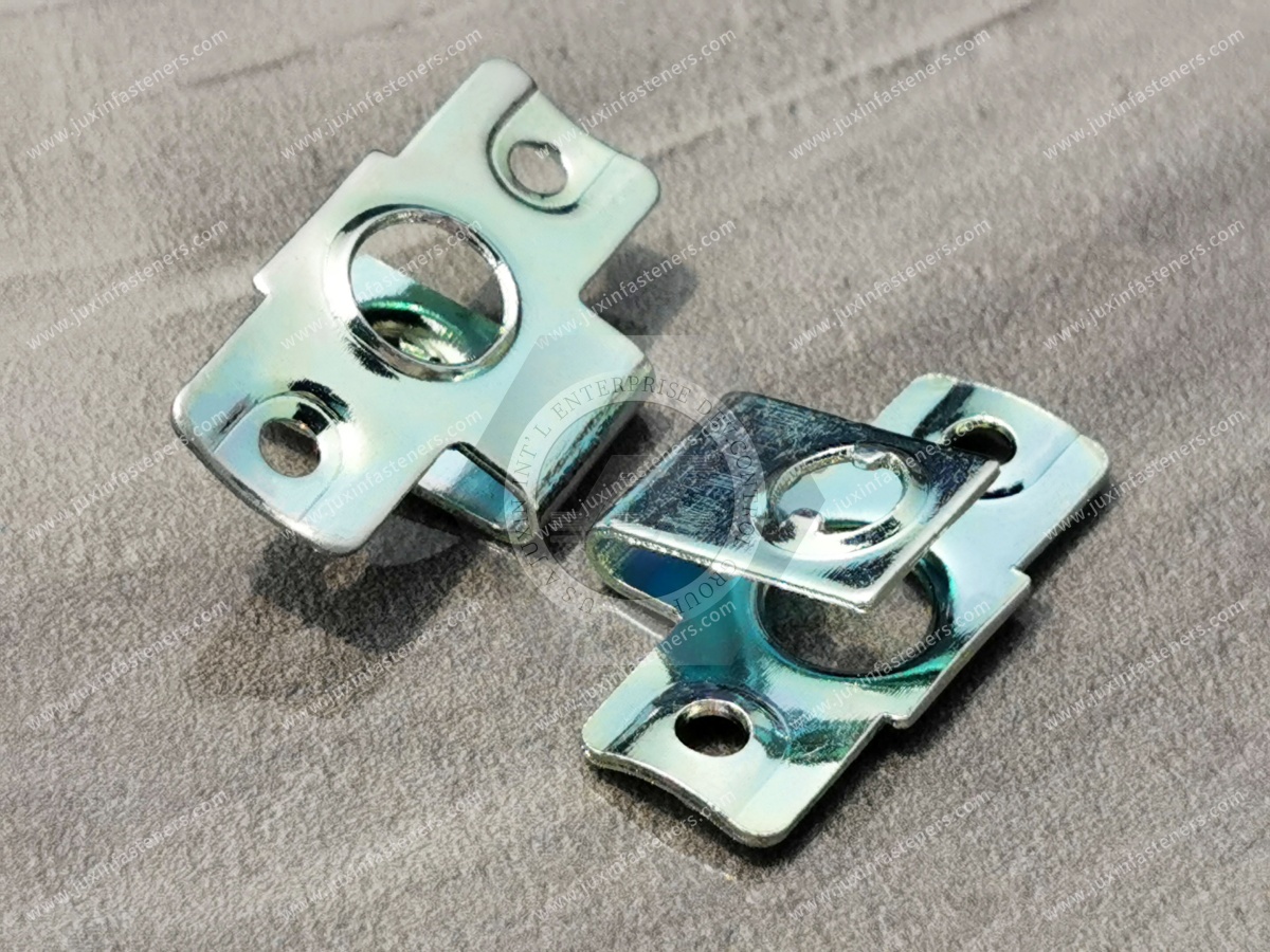
Useful assembly accommodation should not be confused with uncontrolled movement.
Excessive movement can create:
inconsistent screw starting;
rattling;
clip migration;
automation problems.
The required amount of positional freedom should be engineered.
Procurement specifications frequently combine these two different requirements.
Describes how securely the fastener remains on the panel during:
handling;
transportation;
assembly;
screw insertion.
Depends on the complete system:
Clip Thread + Screw + Panel + Mating Component
Therefore:
High Clip Retention ≠ High Final Joint Strength
Spring arms generally provide panel retention.
They should not automatically be treated as a screw-locking mechanism.
Therefore:
Panel Grip Force ≠ Prevailing Thread Torque
If resistance to screw loosening is required, the joint should be evaluated separately.
The RFQ should clearly identify whether the assembly uses:
ISO metric thread;
Unified inch thread;
tapping screw;
another defined thread system.
Never rely only on a nominal diameter.
For general-purpose metric fastening threads, applicable ISO documents define:
basic/design profiles;
diameter and pitch combinations;
basic dimensions;
tolerances.
The production drawing should identify the required thread rather than merely saying:
“Metric thread.”
Global OEMs can reduce unnecessary part proliferation by reviewing whether multiple plants use functionally duplicated metric sizes.
However, standardization should occur only after checking:
panel geometry;
screw requirements;
load;
assembly method;
regional manufacturing constraints.
For North American equipment, Unified inch threads such as UNC or UNF may be required.
The RFQ should define:
nominal size;
threads per inch;
thread series;
applicable drawing requirement.
Do not convert an inch-thread application to metric solely for procurement convenience without engineering approval.
Similar-looking metric and inch clip nuts can create production risk.
Controls can include:
distinct part numbers;
controlled labeling;
packaging identification;
segregated inventory.
A visually similar part is not necessarily interchangeable.
Material should be selected according to:
spring requirement;
environment;
geometry;
manufacturing process;
customer specification.
Common categories include:
specification-controlled carbon spring steel;
stainless spring material where appropriate.
A global OEM specification should preferably communicate the required internationally understood material or performance requirement rather than depending on a regional shorthand such as 65Mn.
The important questions are:
What material specification is required?
What mechanical condition is required?
What spring behavior is required?
What corrosion environment applies?
What customer-specific requirement applies?
Carbon spring steel can provide strong elastic recovery for many clip geometries.
Performance depends on more than the material name.
It also depends on:
thickness;
forming;
heat treatment;
hardness/mechanical condition;
clip geometry.
Stainless materials can be considered where corrosion exposure warrants them.
However:
Stainless ≠ Corrosion-Proof
and:
Stainless ≠ Automatic Functional Equivalent to Carbon Spring Steel
Changing material can alter:
spring behavior;
forming behavior;
dimensions;
cost.
Supplier substitution should therefore be validated.
Surface finish can affect:
corrosion protection;
friction;
dimensions;
appearance;
assembly behavior.
The finish specification should be based on the application rather than a generic requirement for “maximum corrosion resistance.”
ISO 4042 provides requirements for electroplated coating systems on fasteners and includes clips within its scope.
It can therefore be relevant when electroplated steel clip-on nuts are specified.
However, the standard does not by itself define:
the correct clip geometry;
the required corrosion performance for every industry;
the service life of the finished assembly.
A clip is a geometry-sensitive spring component.
Coating thickness can influence:
effective dimensions;
grip behavior;
thread fit;
installation behavior.
Therefore:
Coating Specification ≠ Purely Cosmetic Requirement
For susceptible hardened/high-strength steel components, manufacturing and electroplating processes can create hydrogen-embrittlement risk.
The correct controls depend on:
material;
hardness/strength;
process;
coating system;
stress condition.
Procurement should not automatically request a generic “baking certificate” without understanding the material and process.
Likewise:
One Bake Temperature + One Bake Time ≠ Universal Hydrogen-Embrittlement Solution
If corrosion testing is required, the RFQ should specify:
applicable test method;
exposure duration;
acceptance criteria.
Do not use a generic request such as:
“Highest salt spray hours available.”
The requirement should come from the actual service environment or customer specification.
Laboratory corrosion tests can support coating comparison or specification verification.
They do not directly predict:
years outdoors;
years inside an electrical cabinet;
automotive life;
HVAC service life;
machinery service life.
Some OEM programs require:
material declarations;
certificates;
lot traceability;
inspection records.
Others do not.
The required documentation should be defined in the RFQ.
Do not automatically require an EN 10204 3.1 certificate or full MTR package for every commercial spring clip unless the customer program actually requires it.
A procurement package may define requirements for:
drawing inspection;
dimensional reports;
material documentation;
coating documentation;
sample approval;
packaging identification;
lot traceability.
The correct package depends on the OEM program.
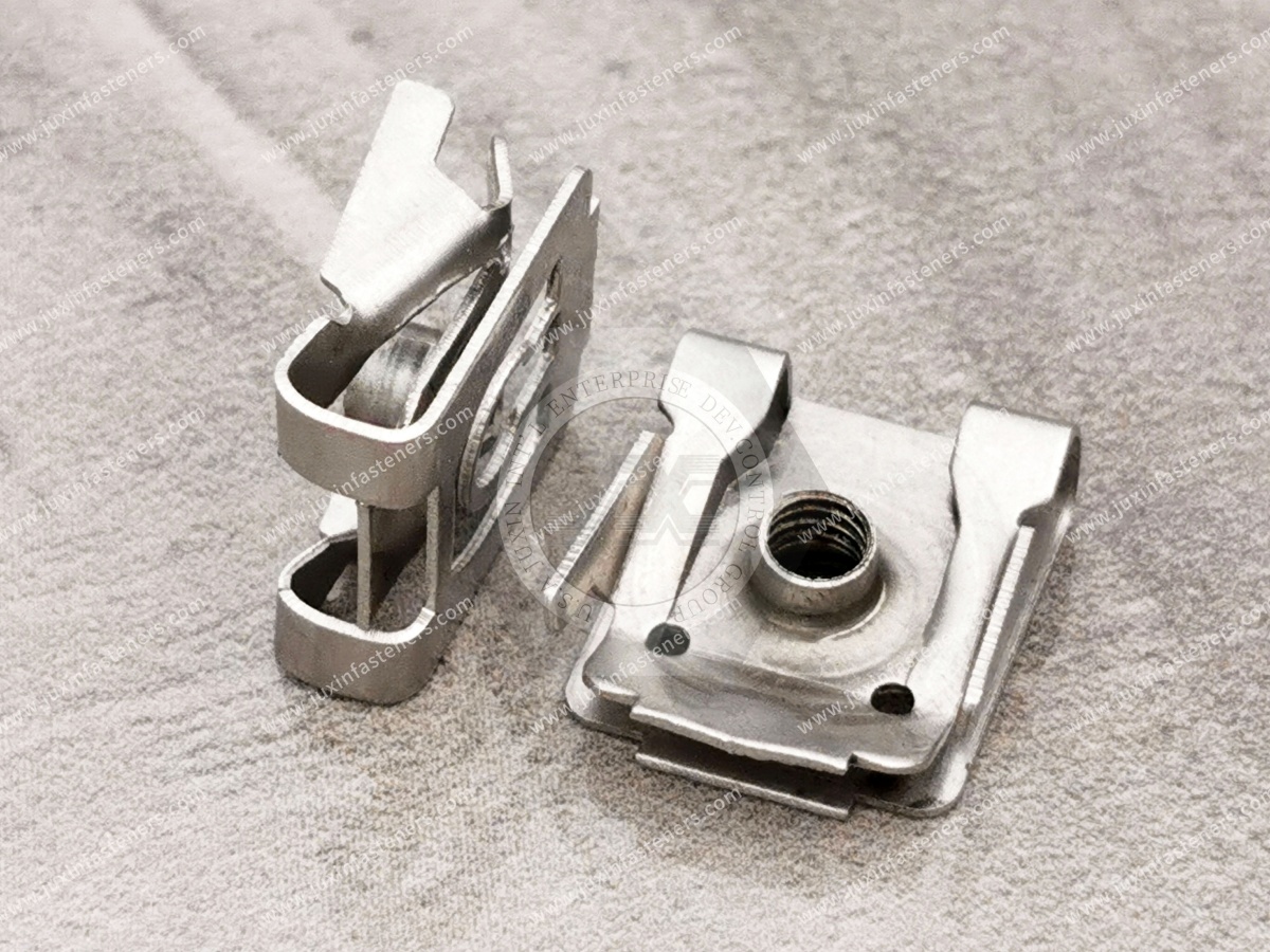
Prototype sourcing often begins with:
catalogue sample;
supplier sample;
existing component.
Before production, the design should be converted into a controlled specification.
That specification can define:
thread;
geometry;
grip range;
material;
finish;
critical dimensions;
functional requirements.
A single sample fitting a single panel does not establish production capability.
Production introduces variation in:
sheet thickness;
bend location;
hole position;
coating thickness;
clip dimensions;
screw dimensions;
assembly equipment.
The production assembly should be evaluated across expected tolerance conditions.
Before releasing an OEM clip-nut RFQ, engineering and sourcing teams should review whether the drawing controls the dimensions that actually determine function.
A useful audit asks:
Can another qualified supplier manufacture a functionally equivalent part from this drawing without guessing?
If the answer is no, the specification is incomplete.
Depending on the design, these can include:
overall width;
overall height;
material thickness;
throat depth;
hole setback;
panel grip range;
thread position;
thread specification;
free-state spring geometry;
functional opening;
material;
finish.
Not every dimension requires the same tolerance.
Critical functional dimensions deserve appropriate control.
Unnecessarily tight tolerances can increase:
manufacturing cost;
inspection cost;
rejection rate.
Tolerance should follow functional need.
The objective is not:
Tightest Possible Drawing
It is:
Controlled Functional Drawing
A physical sample can be useful.
It should not automatically replace the engineering specification.
Samples can help suppliers understand:
geometry;
assembly behavior;
finish;
packaging.
But production acceptance should ideally rely on controlled requirements.
If an OEM is second-sourcing an existing fastener, provide the current:
supplier part number;
drawing;
sample
where commercially and legally appropriate.
This can accelerate cross-reference evaluation.
However, a cross-reference should not be approved solely because the new component looks similar.
Changing a clip-on nut supplier can change:
spring geometry;
material condition;
grip force;
throat depth;
thread position;
coating;
friction;
assembly behavior.
Therefore:
Supplier Change ≠ Pure Purchasing Change
For critical assemblies, the alternative part should be validated against the controlled requirements.
Two suppliers may both sell:
M6 U-Nut for 1.0–1.5 mm Panel
but the components may differ in:
geometry;
material thickness;
free-state shape;
insertion force;
retention;
hole setback;
finish.
This is why sourcing by catalogue description alone creates risk.
Global OEMs often want to reduce fastener part-number count.
This can improve:
purchasing leverage;
inventory control;
supplier management;
plant-to-plant consistency.
However, rationalization should be based on functional equivalence.
A weak strategy is:
“All of these use M6, so use one M6 clip nut.”
That ignores:
panel thickness;
setback;
throat depth;
environment;
load;
service requirement.
A stronger approach groups parts by:
thread system;
panel grip range;
hole setback;
throat depth;
clip architecture;
material/finish;
functional requirements.
Then engineering can identify genuine duplicates.
Many OEMs can identify a relatively small number of clip geometries that cover a large percentage of routine sheet-metal applications.
These can become preferred components.
Less common applications remain drawing-specific.
The goal is not one universal clip nut.
The goal is:
Minimum Practical Part Count Without Compromising Function
A fastener approved at Plant A should not automatically be released at Plant B.
Plant differences may include:
panel supplier;
sheet tolerance;
coating process;
assembly tooling;
screw supplier;
production sequence.
The same BOM number requires the same controlled interface.
Large OEMs can use an internal global part number linked to approved supplier references.
This helps separate:
OEM Functional Specification
from:
Supplier Commercial Catalogue Number
That architecture makes second sourcing easier.
If a clip changes in:
material;
geometry;
coating;
thread construction;
heat treatment;
manufacturing process
the customer should determine whether revalidation is required.
A visually identical clip can behave differently.
Packaging is not only a logistics issue.
Poor packaging can cause:
tangled clips;
deformation;
coating damage;
mixed parts;
difficult line-side handling.
The RFQ should identify how the fastener will be consumed.
Bulk packaging may be suitable for manual assembly or line-side replenishment.
Define:
quantity per bag/carton;
labeling;
lot segregation
where relevant.
Some OEMs may require fasteners to be packed according to:
workstation;
assembly kit;
product configuration.
This should be communicated commercially rather than assumed.
Gemini's original draft assumed high-volume clip nuts should support automated handling.
That is too broad.
Not every clip geometry is suitable for:
bowl feeding;
track feeding;
robotic handling;
automatic placement.
If automation is required, specify it during sourcing.
A clip that is easy for an operator to install may be difficult for an automated system.
Automated installation can require tighter control of:
orientation;
geometry;
position;
insertion force;
packaging.
Therefore:
Manual Assembly Approval ≠ Automated Assembly Approval
The RFQ should state whether installation is:
manual;
hand-tool assisted;
pneumatic;
automated.
This helps the supplier understand the actual manufacturing process.
Likewise, define whether screws are installed using:
manual tools;
controlled electric drivers;
automated screwdriving.
The driver process can influence alignment and joint behavior.
A master sourcing framework can support many industries while maintaining application-specific requirements.
Clip-on nuts can support appropriate:
doors;
covers;
internal brackets;
folded flanges.
Important considerations include:
post-paint installation;
panel thickness;
electrical functional boundaries.
A standard clip-on nut should not automatically be treated as a grounding or bonding component.
Potential applications include:
AHU service panels;
blower housings;
access covers.
The clip provides mechanical attachment.
It should not automatically be treated as an air-sealing fastener.
Potential applications include:
machine enclosures;
maintenance covers;
appropriate guards;
conveyor service panels.
Where a panel performs a personnel-protection function, machinery safety requirements must be evaluated separately.
Low-profile clip-on nuts can support compact:
controller cabinets;
sensor housings;
auxiliary covers.
Dynamic robot structural joints require separate engineering evaluation.
Clip-on nuts can support appropriate:
body panels;
brackets;
service covers;
auxiliary enclosures.
They should not automatically be specified for crash-critical, suspension, steering or primary EV battery structural joints.
Potential applications include appropriate:
equipment cabinets;
service panels;
auxiliary enclosures.
Railway vibration, fire, corrosion and system qualification requirements remain application-specific.
Stainless or other appropriate clip materials can be considered for:
diagnostic housings;
laboratory analyzers;
equipment carts.
The fastener does not automatically provide:
ISO 13485 compliance;
biocompatibility;
sterile qualification;
cleanroom qualification.
A successful sourcing page should answer both.
Engineers may search:
how to select clip-on nuts;
U-nut grip range;
clip nut hole setback;
sheet metal clip nut dimensions;
U-nut vs J-nut;
clip nut panel thickness;
clip nut failure;
clip nut thread selection.
They need engineering decisions.
Buyers may search:
clip nut manufacturer;
OEM clip nut supplier;
bulk U-nut supplier;
spring nut manufacturer;
custom sheet metal fastener supplier;
clip nut second source;
clip nut cross reference.
They need sourcing confidence.
The page must connect both journeys.
A useful hierarchy is:
What equipment and assembly uses the fastener?
U-nut, J-nut, barrel clip, enclosed thread, tapping-screw clip or another geometry?
Panel thickness, edge geometry, hole diameter, setback and finish.
Metric/inch/tapping screw, size, pitch/TPI and mating screw.
Clip retention, joint requirements, vibration/service requirements where applicable.
Material condition, coating/finish and corrosion requirement.
Assembly method, automation, packaging, inspection and documentation.
Sample quantity, pilot volume, annual demand, plant locations and program timing.
This hierarchy reduces quotation ambiguity.
Identify:
equipment;
panel;
attached component;
service function.
Determine whether clip installation from the edge is possible.
Compare:
U-nut;
J-nut;
barrel clip;
enclosed-thread clip;
tapping-screw clip;
alternative sheet-metal fastener.
Specify:
material;
thickness;
tolerance;
finish;
flange width;
bend geometry;
hole diameter;
setback.
Specify:
metric/inch;
nominal size;
pitch/TPI;
mating screw.
Control:
grip range;
throat depth;
overall envelope;
thread position;
required alignment accommodation.
Specify only what the application requires.
Examples may include:
retention;
joint load;
service cycles;
vibration;
environmental exposure.
Specify:
installation method;
automated feeding if required;
screwdriving process;
packaging.
Specify required:
dimensional reports;
material documentation;
coating documentation;
traceability.
Use production-intent:
panel;
screw;
assembly method.
Confirm the component across expected manufacturing tolerances.
Create a controlled:
drawing;
specification;
approved sample/reference where appropriate.
Only then should price comparison become the primary sourcing activity.
A buyer may send five suppliers:
“M6 clip nut, 100,000 pcs/year. Quote please.”
The five quotations may represent five different products.
The lowest price is therefore not necessarily the lowest price for the same technical requirement.
Better sequence:
Specification First → Comparable Quotes Second
Before sending a production RFQ, ask whether the package answers these ten questions:
What does the clip attach?
What panel does it grip?
What is the panel thickness range?
Where is the hole relative to the edge?
What screw/thread system is used?
What clip geometry is required?
What material and finish are required?
What functional conditions apply?
How will it be assembled?
What is the expected commercial volume?
If several answers are missing, the RFQ is likely to produce assumptions rather than comparable quotations.
Unit fastener price is only one part of sourcing economics.
A useful model is:
Fastener Price + Installation Labor + Tooling + Rework + Line Downtime Risk + Inventory + Maintenance + Replacement
A slightly lower unit price can become expensive if the part causes:
cross-threading;
line stoppage;
manual rework;
excessive sorting;
field replacement.
Reducing unnecessary part numbers can reduce:
purchasing complexity;
inventory;
warehouse locations;
line-side errors;
supplier management.
But over-standardization can create mechanical compromises.
The objective is:
Controlled Rationalization, Not Forced Commonality
Second sourcing can reduce supply-chain risk.
However, a second supplier should be qualified against the same functional specification.
Useful comparison criteria can include:
critical dimensions;
panel fit;
thread fit;
installation behavior;
retention;
material/finish;
assembly performance.
A supplier may provide a cross-reference to another manufacturer's part number.
That cross-reference should be treated as a candidate.
Engineering should still verify:
dimensions;
grip;
setback;
thread;
material;
finish;
assembly behavior.
Therefore:
Cross-Reference ≠ Automatic Engineering Approval
A sourcing RFQ should communicate more than annual quantity.
Useful commercial information can include:
prototype quantity;
pilot quantity;
production lot size;
annual volume;
number of manufacturing plants;
expected program duration;
demand variability.
This helps align manufacturing and packaging strategy.
Projected annual demand helps commercial planning.
It should be distinguished from a firm purchase commitment.
Clear demand communication improves supply planning without creating ambiguity.
A drawing-specific design may be justified when standard products cannot satisfy:
grip range;
throat depth;
restricted envelope;
hole setback;
thread location;
retention requirement;
assembly constraints.
The business case should consider:
tooling;
validation;
expected volume;
lifecycle demand.
A standard or established geometry may be preferable when it satisfies the engineering requirements because it can reduce:
tooling;
development time;
sourcing complexity.
Custom does not automatically mean better.
Do not assume that:
every M6 clip nut is interchangeable;
every U-nut floats;
stronger clip grip means stronger joint;
spring grip prevents screw loosening;
stainless is corrosion-proof;
more salt-spray hours means longer service life;
every plated clip requires the same hydrogen-relief process;
every supplier must provide the same certificate package;
every clip can be automatically fed;
every clip-on nut works on every sheet thickness;
every supplier cross-reference is a drop-in replacement.
These assumptions create avoidable sourcing risk.
Avoid releasing a drawing that omits critical:
panel thickness;
hole setback;
thread;
throat depth;
grip requirement;
material;
finish.
A supplier should not have to reverse-engineer the design intent from a photograph.
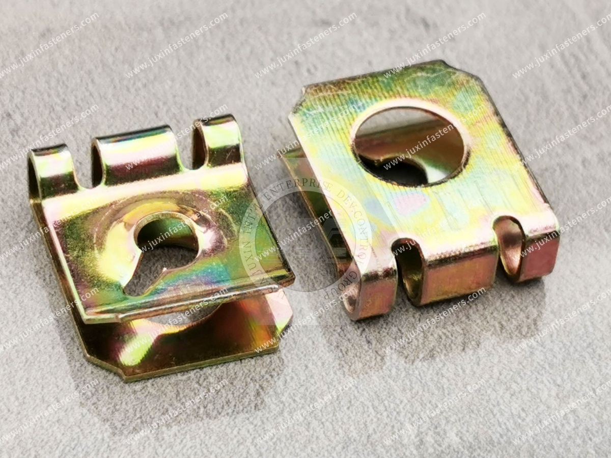
When qualifying a new clip-on nut supplier, compare:
drawing interpretation;
sample geometry;
thread quality;
panel fit;
assembly behavior;
material/finish conformity;
production consistency;
packaging;
documentation capability;
commercial scalability.
Supplier qualification should evaluate the complete sourcing requirement rather than one sample dimension.
When submitting an RFQ to JUXIN FASTENERS, provide where applicable:
OEM/project name or internal project reference;
industry/application;
assembly description;
2D drawing;
3D model where available;
assembly drawing;
current part sample;
current supplier part number where appropriate;
required fastener architecture;
U-nut/J-nut/barrel/enclosed/tapping-screw type;
metric or inch system;
thread diameter;
pitch or TPI;
thread tolerance requirement where defined;
mating screw specification;
screw material;
screw finish;
screw length;
screw-head style;
panel material;
nominal panel thickness;
panel-thickness tolerance;
finished thickness where relevant;
panel coating/finish;
flange width;
flange geometry;
bend radius where relevant;
hole diameter;
hole setback;
throat depth;
maximum fastener envelope;
required alignment accommodation where applicable;
clip-retention requirement where defined;
joint mechanical requirement;
service-cycle requirement;
vibration/shock requirement where relevant;
operating temperature;
humidity;
corrosion environment;
chemical/fluid exposure;
fastener material requirement;
coating/finish specification;
corrosion-test method where required;
corrosion-test duration where required;
acceptance criteria;
hydrogen-embrittlement control requirement where applicable;
installation method;
automated-feeding requirement if applicable;
automated-placement requirement if applicable;
screwdriving method;
packaging format;
quantity per package;
labeling requirement;
lot-traceability requirement;
inspection requirement;
material documentation requirement;
coating documentation requirement;
customer-specific quality requirement;
sample quantity;
prototype quantity;
pilot quantity;
production order quantity;
estimated annual usage;
number of manufacturing plants;
program timing;
forecast information;
required delivery destination/incoterm where relevant.

Start with the panel and assembly interface, define the fastener geometry and thread system, establish material/finish and functional requirements,
evaluate production-intent samples, then compare commercial quotations against the same controlled specification.
Depending on the design, critical dimensions can include panel grip range, throat depth, hole setback, overall envelope, thread position and relevant spring geometry.
No. Two fasteners with the same thread can have different panel interfaces and assembly behavior.
No. Positional accommodation depends on the specific geometry.
Only if the applications share compatible panel geometry, grip, setback, throat depth, material/finish and functional requirements.
Metric standardization can simplify some portfolios, but existing inch applications should not be converted without engineering review.
Where applicable, ISO general-purpose metric thread standards can define thread profile, selected sizes, basic dimensions and tolerances. The actual drawing should identify the required thread specification.
ISO 4042 applies to electroplated fasteners within its scope, including clips. The actual coating system and performance requirements still need to be specified for the application.
Not automatically. Documentation requirements should follow the OEM program and controlled specification.
No. Hydrogen-embrittlement controls should be based on the material, hardness/strength, process and applicable specification rather than a universal requirement.
Some designs may be compatible with automated feeding, but this must be evaluated for the actual geometry and assembly system.
It should normally be treated as a candidate equivalent and verified against the controlled engineering requirements.
JUXIN FASTENERS can review available drawings, samples, current part references, panel geometry, screw requirements,
material/finish requirements and projected demand to identify candidate clip-on nut configurations for evaluation.
A purchasing inquiry may begin:
“We need 100,000 pcs M6 clip nuts. Please quote.”
But procurement cannot know whether supplier quotations are technically comparable until engineering answers:
What Clip Architecture?
What Panel Thickness?
What Grip Range?
What Hole Setback?
What Throat Depth?
What Screw?
What Material?
What Finish?
What Operating Environment?
What Assembly Process?
What Documentation Is Actually Required?
The correct commercial pathway is:
Application → Fastener Architecture → Panel Interface → Thread / Screw → Geometry → Material / Finish
→ Functional Requirements → Production Requirements → Controlled Drawing → Samples → Assembly Validation → Approved Specification → Comparable Supplier RFQ → Production Sourcing
That is the difference between purchasing a catalogue description and sourcing a controlled OEM component.
JUXIN FASTENERS supports OEM and industrial sourcing for sheet-metal clip-on nut applications including:
U-nuts;
J-nuts;
strong-grip clip-on nuts;
barrel clip-on nuts;
enclosed hex clip-on nuts;
low-profile clip-on nuts;
tapping-screw spring clips;
metric clip-on nuts;
inch clip-on nuts;
carbon spring-steel clips;
stainless spring clips where appropriate;
drawing-based spring fasteners.
Applications can include appropriate:
automotive assemblies;
EV auxiliary assemblies;
electrical cabinets;
switchgear;
HVAC equipment;
industrial machinery;
robotics and automation;
rail equipment;
electronics;
medical and laboratory equipment;
general OEM sheet-metal chassis and enclosures.
For related engineering guidance, see:
Sheet-Metal Fastener Selection Guide
Panel Thickness Selection Guide
Metric Clip-On Nuts Selection Guide
Inch Clip-On Nuts Selection Guide
Carbon Steel Clip-On Nuts: Material & Coating Guide
304 vs 316 Stainless Steel Clip-On Nuts
Strong-Grip Clip-On Enclosed Hex Nuts
Strong-Grip Clip-On Barrel Nuts & U-Nuts
Clip-On Nuts for Flanged Edges
For an OEM clip-on nut sourcing project, second-source review or drawing-based RFQ, send your 2D drawing,
3D model where available, current sample or part number, panel material and thickness, hole setback, throat depth,
thread and mating screw requirements, material/finish specification, production assembly requirements, sample quantity and projected annual demand to:
The most effective procurement question is not:
“Who can supply this M6 clip nut at the lowest unit price?”
It is:
“Which supplier can consistently manufacture the defined panel interface, thread system, spring geometry, material, finish and production requirements across the complete OEM program?”
That question turns clip-on nut purchasing into controlled strategic sourcing.
 MORE NEWS
Contact Us
Tel.:
+86 020 8621 0320
+86 020 3121 6067
E-mail:
Technical Support:
Navigation
SEND INQUIREY