
Call Us
+86 136 6007 9809
Call Us
+86 136 6007 9809

Sep. 21, 2026
In high-volume sheet-metal assembly, selecting the correct clip-on nut is only half of the fastening decision.
The mating screw is the other half.
A correctly selected U-nut, J-nut, barrel clip nut or enclosed-thread clip can still produce assembly failures if the mating screw has the wrong:
thread family;
diameter;
pitch or threads per inch;
tolerance relationship;
length;
tip geometry;
material;
surface finish;
tightening condition.
Likewise, a screw that works correctly with one spring fastener should not automatically be assumed compatible with another fastener that appears visually similar.
For OEM design engineers, manufacturing engineers and procurement teams, clip nut screw compatibility should therefore be treated as a controlled fastening-system requirement rather than a catalogue afterthought.
The correct engineering model is:
Clip Architecture + Thread System + Mating Screw + Panel Geometry + Alignment + Tightening Process + Joint Requirement
All seven interfaces matter.
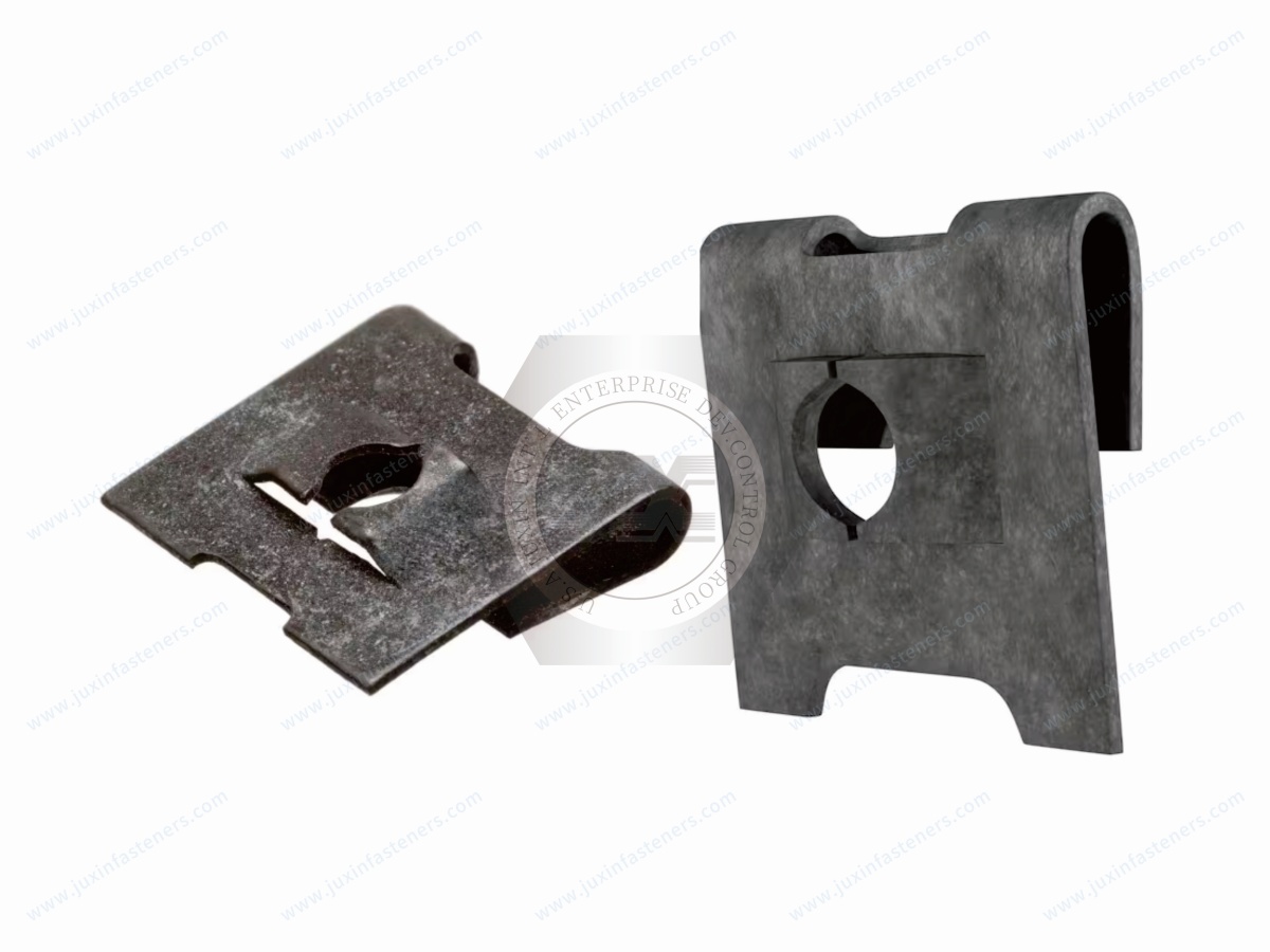
Before discussing thread engagement, engineers should identify the fastening architecture.
Two broad systems commonly encountered in spring fasteners are:
Machine-Thread Clip-On Nut + Machine Screw
and
Tapping / Thread-Forming Screw + Purpose-Designed Spring Clip
They are not automatically interchangeable.
This distinction is fundamental.
Machine-thread clip-on nuts provide an internal threaded feature intended to mate with a compatible machine screw.
Depending on the design, products can include:
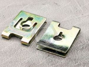
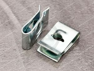
U-nuts;
J-nuts;
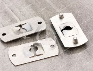
enclosed-thread clip nuts;
barrel clip nuts;
other captive spring-nut configurations.
The screw and internal thread must be compatible in:
nominal diameter;
pitch or TPI;
thread form;
relevant tolerance relationship.
Other spring fasteners are specifically designed to work with tapping or thread-forming screws.
These systems rely on a different engagement mechanism.
The mating screw interacts with a purpose-designed spring feature or receiving geometry rather than simply entering a conventional machine-thread nut.
For related product selection, see Strong-Grip Clip-On Nuts for Tapping Screws.
A tapping screw should not automatically be driven into a machine-thread clip-on nut.
Likewise, a conventional machine screw should not automatically be substituted into a spring clip designed around a specific tapping-screw geometry.
The screw and clip must be engineered as a compatible pair.
Therefore:
Similar Diameter ≠ Compatible Thread System
Thread-forming screws can create or form their mating thread in appropriate materials and specifically designed receiving features.
However, this does not mean they universally create a “zero-clearance” joint.
Nor does thread forming automatically guarantee resistance to vibrational loosening.
Performance depends on:
screw geometry;
receiving feature;
material;
engagement;
installation process;
final joint design.
Therefore:
Thread Forming ≠ Automatic Thread Locking
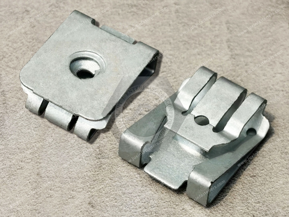
Some clip-on nuts use thread-bearing features produced from relatively thin material or captive threaded elements rather than the thick body of a conventional solid nut.
This changes the mechanical architecture.
However, it is important not to generalize all clip-on nuts as having the same “spring-formed thread.”
Different designs may use:
formed threaded features;
stamped thread features;
captive nut elements;
barrel-style threaded elements;
purpose-designed tapping-screw engagement features.
The actual fastener construction should be identified before defining screw compatibility.
The clip body itself provides spring behavior for panel retention.
Some clip architectures may also permit limited positional compliance.
But it should not be assumed that the threaded element intentionally expands radially during normal screw installation.
A machine-thread clip nut should normally be treated as a defined threaded interface.
If the screw must force, reform or significantly distort the receiving thread during assembly, the combination requires specific validation.
Certain clip-on nut designs can provide limited positional accommodation.
This may help the screw find the thread when there are small assembly variations.
However:
Compliance ≠ Permission for Misalignment
Excessive angular or lateral misalignment can cause:
cross-threading;
abnormal rundown torque;
thread damage;
incomplete seating;
false torque readings.
Screw compatibility cannot be evaluated independently from the panel.
Alignment depends on the relationship between:
panel edge;
panel hole;
hole setback;
clip throat depth;
thread center;
mating component hole.
A correctly manufactured screw can still bind if these features are misaligned.
Hole setback defines the relationship between the panel edge and the screw axis.
If the setback is incorrect relative to the clip geometry, the screw may enter the threaded feature at an angle.
Potential consequences include:
difficult screw starting;
elevated rundown torque;
cross-threading;
partial engagement;
thread deformation.
Two M6 clip-on nuts can have different throat depths.
Therefore:
Same Thread Size ≠ Same Thread Position
The selected clip must position its threaded feature correctly relative to the panel hole.
For general geometry troubleshooting, see Clip-On Nut Failure Analysis.
For ISO general-purpose metric machine-thread systems, the engineering specification should identify more than the letter “M.”
For example:
M6
alone does not communicate every required thread detail.
The specification may need to define:
nominal diameter;
pitch;
applicable thread requirement;
tolerance where relevant.
ISO general-purpose metric screw threads are defined through a family of standards.
The framework includes standards covering:
basic/design thread profiles;
general diameter/pitch planning;
selected commercial fastener sizes;
basic dimensions;
thread tolerances.
These standards help engineers define a compatible metric thread system.
They do not by themselves define the complete mechanical performance of a clip-on nut assembly.
A nominal diameter can exist with more than one pitch.
Therefore, specifying:
M8
without the required pitch can create sourcing ambiguity where more than one pitch is possible.
A controlled drawing should identify the intended thread.
Unified inch systems require similar discipline.
An inch-thread specification should identify:
nominal size;
threads per inch;
thread series where applicable;
relevant tolerance/class requirement where necessary.
For example, two screws with similar major diameters but different TPI values are not compatible.
For inch product selection, see Inch Clip-On Nuts Selection Guide.
Some metric and inch fasteners can appear very similar.
Production teams should never identify compatibility only by visual inspection.
A wrong screw can sometimes start into the incorrect thread before binding.
That creates a particularly dangerous assembly condition because the operator may continue tightening.
Potential results include:
damaged internal threads;
screw damage;
high false torque;
inadequate clamp;
hidden assembly defects.
Pitch mismatch is one of the most fundamental screw-compatibility failures.
If the screw and nut have different pitch or TPI:
thread flanks cannot engage correctly;
interference increases rapidly;
the screw may bind;
threads may deform.
Therefore:
Nominal Diameter Match ≠ Thread Match
Diameter and pitch alone do not always establish complete compatibility.
The intended thread system and form must also be correct.
Do not substitute a different thread family merely because the nominal dimensions appear close.
For conventional machine-thread systems, thread tolerances influence:
fit;
assembly;
interchangeability.
However, clip-on nut thread performance should not be reduced to a generic assumption that every spring fastener uses the same conventional internal-thread tolerance class.
The actual product drawing and manufacturing method should control the requirement.
For ISO general-purpose metric screw threads, ISO 965-1:2026 establishes the tolerance-system principles and basic data.
This is useful when defining conventional metric threaded interfaces.
But a compliant thread designation alone does not establish:
clip retention;
strip torque;
assembly torque;
joint strength.
These remain separate engineering requirements.
One of the most important design questions is:
How much of the intended thread-bearing feature is effectively engaged by the mating screw?
Effective engagement influences the load transferred through the internal and external threads.
However, there is no universal rule that every clip-on nut requires the screw to protrude a fixed number of threads beyond the fastener.
The requirement depends on the actual threaded architecture.
Gemini's original draft stated that the screw must pass completely through the active spring thread turns.
That may be appropriate for certain designs, but it should not be treated as a universal clip-nut requirement.
What matters is that the assembly provides sufficient effective engagement for the intended load and tightening condition without creating interference.
Therefore:
Required Engagement Must Be Defined by the Actual Fastener Design
Insufficient effective engagement can increase the risk of:
thread stripping;
localized thread deformation;
incomplete load transfer;
unreliable tightening.
The limiting component may be the clip thread rather than the screw.
A longer screw is not automatically safer.
Excessive screw protrusion can interfere with:
electronics;
wiring;
moving components;
internal brackets;
insulation;
adjacent panels;
batteries;
cooling components.
Therefore screw length should be selected from the complete assembly stack-up.
A practical screw-length review should consider:
Screw Head / Bearing Interface → Attached Component → Washer if Used → Panel Stack → Clip Thread → Required Engagement → Available Rear Clearance
This is especially important in:
compact electrical enclosures;
EV electronics;
robotics;
appliances;
HVAC equipment.
When a threaded joint is tightened, load is transferred through the engaged thread flanks.
If the internal thread-bearing feature cannot support the applied load, stripping can occur.
Potential influences include:
engagement geometry;
fastener material;
screw material;
thread geometry;
manufacturing condition;
tightening torque;
alignment.
Strip torque is the torque at which the threaded system loses its ability to sustain further tightening under the specified test condition because a relevant thread or surrounding feature fails.
But strip torque should never be quoted without test context.
A meaningful strip-torque result should identify:
screw used;
clip used;
panel condition where relevant;
assembly orientation;
test method;
tightening speed;
lubrication/surface condition;
failure definition.
These two values serve different purposes.
The torque intended for normal assembly.
The torque associated with destructive or function-losing thread failure under the defined test.
Production tightening should operate within an engineered process window below relevant failure thresholds.
There is no universal percentage that applies to every clip-on nut assembly.
A high strip torque does not automatically mean the joint has high:
tensile capacity;
shear capacity;
fatigue strength;
vibration durability.
It measures a specific failure boundary under specific conditions.
Rundown torque is another quantity that should be separated from final tightening torque.
During screw installation, torque may be consumed before the joint is fully seated because of:
thread friction;
interference;
prevailing features where intentionally present;
alignment problems;
thread-forming work;
contamination.
This is particularly important in automated assembly.
Suppose an electric screwdriver reports high torque.
It is tempting to assume that the joint is tightly clamped.
But the torque may actually result from:
cross-threading;
pitch mismatch;
damaged threads;
misalignment;
excessive interference.
Therefore:
High Rundown Torque ≠ High Clamp Load
Engineers should understand when the joint actually seats and when additional torque begins generating meaningful clamp.
In automated production, torque-angle or other monitored signatures may sometimes help identify abnormal assembly behavior when the process and joint justify that level of control.
This is an assembly-process decision, not an inherent property of the clip nut.
For compatible machine-thread fasteners, applied torque and resulting clamp force are strongly affected by friction.
Relevant interfaces can include:
screw thread;
internal thread;
screw-head bearing surface;
washer where used;
coating;
lubricant.
Therefore, the same nominal screw and clip geometry can behave differently after a surface-finish change.
ISO 16047 provides standardized conditions for torque/clamp-force testing of threaded fasteners and related parts within its scope.
It can be useful when a compatible conventional threaded system falls within the relevant requirements.
However, it specifically excludes screws that form their own mating thread.
Therefore:
Machine-Thread Torque/Clamp Testing ≠ Automatically Applicable to Tapping-Screw Spring-Clip Systems
Purpose-designed test methods may be required for the latter.
A change in screw finish can alter:
friction;
rundown behavior;
achieved preload;
tightening consistency.
Therefore, changing from one screw coating to another should not automatically be treated as a cosmetic change.
The clip's surface condition can influence:
thread friction;
panel installation;
corrosion behavior.
If a screw-and-clip combination has already been validated, changing the coating system can justify re-evaluation.
Some fasteners may have:
intentional lubricant;
coating-integrated friction modifiers;
dry surface condition.
The assembly specification should reflect the actual production condition.
Adding lubricant without engineering approval can change torque/preload behavior.
The mating screw should be selected for the actual assembly requirement.
A stronger screw does not automatically make the joint stronger.
If the screw capacity greatly exceeds the clip-thread or panel capacity, failure may simply shift to the weaker component.
Therefore:
Higher Screw Strength ≠ Higher Complete Joint Strength
For a machine-thread clip-on nut, verify:
thread system;
nominal diameter;
pitch/TPI;
thread form;
applicable tolerance relationship;
screw length;
effective engagement;
screw tip;
screw material/property requirement;
screw finish;
head style;
bearing interface;
drive system;
tightening process.
For a tapping-screw spring clip, verify:
screw family;
nominal screw size;
thread geometry;
tip/point geometry;
receiving clip geometry;
clip material and thickness;
required driving behavior;
final tightening condition;
reusability requirement.
Do not substitute another tapping screw based only on nominal diameter.
Terminology should be controlled because different screw families can create their mating engagement through different mechanisms.
The selected screw must match the receiving feature for which the spring clip was designed.
A generic RFQ stating:
“Use self-tapping screw”
may be insufficient.
If a service panel using a tapping-screw spring clip will be removed repeatedly, engineers should consider whether repeated screw insertion affects:
receiving geometry;
tightening behavior;
strip resistance;
service life.
A joint optimized for one-time production assembly may not automatically be optimized for frequent maintenance.
Where repeated servicing is expected, a machine-thread clip-on nut may offer advantages for certain applications.
However, repeated service can still affect:
internal threads;
clip position;
panel edge;
screw condition.
Therefore:
Machine Thread ≠ Unlimited Reuse
Screw-tip geometry can influence starting behavior.
In compact assembly environments, a suitable lead-in can help the screw enter the intended threaded feature.
But tip design cannot compensate for gross misalignment.
Cross-threading occurs when the screw does not correctly follow the intended mating thread.
Potential causes include:
angular misalignment;
lateral misalignment;
wrong pitch;
damaged thread;
poor starting geometry;
excessive installation speed.
Cross-threading can produce high torque without useful clamp.
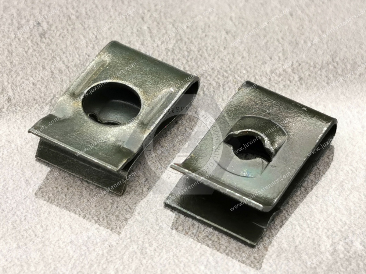
The threaded element is positioned relative to a sheet-metal edge.
Its location therefore depends on:
clip geometry;
panel edge;
hole setback;
panel hole;
mating-part hole.
Tolerance accumulation across these features can shift the screw axis away from the thread axis.
The hole in the panel often serves as a screw-clearance and alignment feature.
It should not automatically be sized from the clip thread designation alone.
Panel hole size should be controlled according to:
screw diameter;
assembly clearance;
clip geometry;
positional tolerance.
Procurement may focus heavily on the clip dimensions while overlooking the customer's sheet-metal tolerance.
A perfectly manufactured clip cannot correct a badly positioned panel hole beyond its designed accommodation range.
Therefore, failure analysis should evaluate both:
Fastener + Panel
not only the purchased clip.
A clip can fit the panel perfectly and still have an incompatible screw.
Likewise, a screw can fit the thread correctly while the clip fits the panel poorly.
These are separate interfaces.
The complete system is:
Panel ↔ Clip ↔ Thread ↔ Screw ↔ Mating Component
A clip's ability to remain on the panel before assembly does not define its final threaded-joint capacity.
For a detailed mechanical explanation, see the related engineering guide on spring nut retention force, clamp load and complete joint strength.
Thread stripping is not one single mechanism.
Depending on the design, failure can involve:
internal thread deformation;
screw thread damage;
local clip deformation;
captive thread-element movement;
surrounding spring-feature distortion.
Failure analysis should identify what actually failed.
Excessive tightening can cause:
thread stripping;
clip deformation;
panel deformation;
screw failure;
bearing-surface damage.
Increasing installation torque should never be used as a generic solution for loose assemblies.
Too little effective tightening can leave:
inadequate clamp;
joint movement;
rattling;
reduced resistance to service loads.
However, the correct solution is not simply “increase torque.”
The entire torque/preload and joint architecture should be evaluated.
A screw can be perfectly compatible with the clip thread and still loosen under an unsuitable joint condition.
Conversely, a screw may bind because of incompatibility even if it never loosens.
Therefore:
Thread Compatibility ≠ Loosening Resistance
The spring force that retains the clip on the panel should not be confused with a thread-locking mechanism.
If screw-loosening resistance is required, engineers should evaluate the complete joint and, where appropriate, a dedicated locking strategy.
Automated assembly introduces additional variables.
These can include:
spindle speed;
approach alignment;
torque control;
angle monitoring;
screw feeding;
seating detection.
A screw-and-clip combination that works manually should not automatically be assumed suitable for automated installation.
For some fastening systems, high installation speed can affect:
heat;
friction;
thread-forming behavior;
torque signature.
This is particularly relevant for tapping/thread-forming systems.
Production validation should use representative equipment.
If the tightening process depends on torque control, the assembly system should use appropriately controlled equipment and the manufacturer's production quality procedures.
The fastener cannot compensate for an uncontrolled assembly process.
Screw compatibility also includes the head and drive system.
Engineers should check:
driver-bit access;
head clearance;
surrounding geometry;
service-tool requirements.
A mechanically compatible thread can still be a poor assembly choice if the driver cannot access it.
Screw head geometry influences:
bearing area;
local panel pressure;
available clearance.
The selected head style should match the clamped component and assembly envelope.
Where washers are used, they become part of the stack-up.
They can change:
screw length requirement;
bearing condition;
clamp distribution.
Do not add or remove washers without checking the validated joint configuration.
A common production problem occurs when several screws share:
the same diameter;
the same pitch;
the same head style
but have different lengths.
The wrong length can assemble successfully while damaging hidden components.
Part-number and line-side controls should therefore prevent screw-length mixing.
Mixed metric/inch manufacturing environments need robust controls.
Useful measures can include:
distinct part numbers;
labeling;
segregated packaging;
controlled line-side presentation.
This reduces accidental thread-family mixing.
A replacement clip may match:
nominal thread;
panel thickness;
approximate shape.
But differences in:
thread geometry;
material thickness;
finish;
alignment;
throat depth
can change screw behavior.
Therefore:
Clip Supplier Change ≠ Automatically Screw-System Equivalent
Likewise, replacing the mating screw can change:
friction;
thread dimensions;
tip geometry;
coating;
head bearing condition.
A validated joint is a matched assembly, not merely two nominal part numbers.
A prototype may be assembled slowly by an experienced engineer.
Production may use:
higher driver speed;
different tooling;
automated screw feeding;
production-tolerance panels.
Therefore:
Prototype Success ≠ Production Process Validation
A useful validation plan separates several questions.
Confirm:
screw diameter;
pitch/TPI;
thread form;
clip geometry;
hole position;
engagement;
screw length.
Evaluate:
starting;
alignment;
rundown behavior;
seating;
tightening.
Where required, evaluate:
strip behavior;
thread deformation;
panel deformation;
screw failure.
Evaluate application-specific:
clamp;
tensile loading;
transverse loading;
vibration;
thermal cycling;
service cycles.
Repeat with representative:
production screws;
production clips;
production panels;
coatings;
assembly tools.
A supplier may provide an impressive strip-torque number.
But engineering still needs to know:
What screw was used?
What panel was used?
What speed was used?
What finish was used?
What failure occurred?
How does it compare with production tightening?
A number without test context is not a complete specification.
| Engineering Variable | Machine-Thread Clip Nut | Tapping-Screw Spring Clip |
|---|---|---|
| Screw system | Defined machine thread | Defined tapping/thread-forming screw system |
| Diameter | Must match specified thread | Must match validated clip/screw design |
| Pitch / TPI | Must match | Screw geometry must match receiving feature |
| Thread tolerance | Relevant to defined machine-thread interface | Conventional machine-thread tolerance may not describe the system |
| Effective engagement | Must be sufficient for design | Depends on formed engagement geometry |
| Rundown torque | Mainly friction/alignment before seating | May include material-forming work |
| Strip behavior | Thread system dependent | Screw/clip forming interface dependent |
| ISO 16047 applicability | Potentially applicable within its defined scope | Not applicable to screws forming their own mating thread |
| Repeated servicing | Requires validation | Particularly important to validate |
| Screw substitution | Requires compatibility review | Requires compatibility review |
General fabricated enclosures can use both machine-thread clip nuts and tapping-screw spring clips depending on:
serviceability;
production speed;
load;
cost;
assembly method.
The screw system should be selected early enough to control the panel design.
Potential applications can include appropriate:
trim brackets;
body panels;
electronic housings;
service covers;
auxiliary assemblies.
Automated screwdriving makes compatibility particularly important.
Primary structural, crash-critical, suspension, steering and other safety-critical applications require dedicated engineering and qualification.
Spring fasteners may support:
equipment housings;
access panels;
blower covers;
service assemblies.
Frequent maintenance can make screw-system selection important.
The fastener itself should not be treated as an air-sealing mechanism.
High-volume appliance assembly can use spring clips because they can support efficient sheet-metal fastening.
For automated or semi-automated production, screw:
feeding;
starting;
rundown;
seating
should be validated together with the clip.
Machine-thread clip-on nuts can provide removable threaded attachment points on suitable cabinet flanges.
The screw-and-clip system does not automatically provide:
electrical bonding;
grounding;
EMI continuity;
ingress protection.
These require separate system design.
Service covers and appropriate machine guards may require repeated screw removal.
Thread durability and service-cycle requirements should therefore be considered.
Safety-related guard assemblies must also satisfy the applicable machinery safety design requirements independently of the clip-nut specification.

Compact controller housings and sensor enclosures can create very limited rear clearance.
Screw length and protrusion become particularly important.
A screw that is only a few millimeters too long may interfere with:
cables;
PCB assemblies;
sensors;
moving components.
Engineers may search:
clip nut screw compatibility;
U-nut screw size;
clip nut thread engagement;
spring nut strip torque;
why screw binds in clip nut;
thread-forming screw spring clip;
machine screw vs tapping screw clip;
clip nut torque.
Their goal is to prevent mechanical or assembly failure.
Purchasing teams may search:
clip nut and screw supplier;
spring nut manufacturer;
U-nut supplier;
tapping screw clip supplier;
OEM clip nut manufacturer;
custom spring fastener supplier.
Their goal is to obtain a commercially scalable, technically compatible system.
The RFQ should connect both needs.
Determine whether the application uses:
machine-thread clip nut;
tapping-screw spring clip;
another fastener system.
Define:
metric;
Unified inch;
tapping/thread-forming;
another controlled system.
For machine threads, specify the complete thread designation.
Confirm:
panel thickness;
hole diameter;
hole setback;
throat depth.
Review the complete stack-up from the screw entry point to the clip thread.
Use the actual fastener design and load requirement rather than a generic thread-count rule.
Check engagement and rear clearance.
Match them to:
mechanical requirement;
environment;
validated friction condition.
Specify:
manual/automated;
target tightening condition;
production tool.
Where necessary, evaluate:
strip behavior;
panel deformation;
screw failure.
Evaluate relevant:
vibration;
thermal cycling;
repeated removal;
environment.
Control both the clip and mating screw in the production documentation.
When requesting a quotation or engineering review from JUXIN FASTENERS, provide where applicable:
application;
assembly description;
2D fastener drawing;
3D model where available;
assembly drawing;
existing clip sample;
existing screw sample;
current supplier references where appropriate;
clip type;
clip geometry;
machine-thread or tapping-screw system;
metric or inch system;
nominal screw diameter;
pitch or TPI;
complete thread designation;
thread tolerance/class where applicable;
screw type;
screw length;
screw tip/point geometry;
screw head style;
drive type;
screw material/property requirement;
screw coating/finish;
lubrication/friction requirement where defined;
panel material;
panel thickness;
panel-thickness tolerance;
panel finish;
hole diameter;
hole setback;
throat depth;
attached-component thickness;
washer thickness where applicable;
maximum permitted rear protrusion;
required effective engagement;
assembly orientation;
manual or automated installation;
driver type;
driver speed where relevant;
target tightening torque where defined;
rundown limits where defined;
strip-torque requirement where defined;
torque/clamp-force test requirement where applicable;
repeated service-cycle requirement;
vibration/shock requirement;
operating temperature;
environmental exposure;
corrosion requirement;
sample quantity;
pilot quantity;
production order quantity;
projected annual volume;
packaging requirement;
quality/documentation requirement.
Identify the clip's intended screw system, then verify diameter, pitch/TPI, thread form, geometry, engagement, screw length, alignment and tightening process using production-intent components.
Not automatically. Machine-thread clip nuts and tapping-screw spring clips are different fastening architectures.
Not automatically. Thread geometry, point design, material and receiving clip geometry can affect compatibility.
Possible causes include excessive tightening torque, insufficient engagement, misalignment, incompatible screw/thread geometry, damaged threads and an unsuitable screw/clip combination.
There is no universal number that applies to every clip-on nut architecture. Required effective engagement should be established from the actual fastener design and validated assembly requirements.
Only where required by the particular fastener design and assembly. Excessive protrusion can create interference.
Possible causes include pitch mismatch, cross-threading, misalignment, damaged threads, excessive interference or an incompatible screw/clip system.
Not necessarily. Friction and assembly interference can consume torque without creating the intended clamp.
Rundown torque occurs while the screw advances before final joint tightening. Final tightening torque occurs as the seated joint develops clamp. Abnormally high rundown torque can indicate an assembly problem.
It is a failure-related torque measured under defined test conditions at which the threaded system loses functional integrity. It is not the normal production tightening torque.
ISO 16047 excludes screws that form their own mating thread, so it should not be applied generically to tapping/thread-forming screw spring-clip systems.
Yes. Surface condition can influence friction and therefore tightening behavior.
Not necessarily. A stronger screw can shift the failure to the clip thread or surrounding sheet-metal structure.
Possibly, but automated screwdriving introduces different alignment, speed and process-control requirements and should be validated.
JUXIN FASTENERS can review available screw and clip samples, drawings, panel geometry, thread requirements,
tightening conditions and projected production demand to identify candidate configurations for customer evaluation.
An RFQ may begin with:
“We need an M6 clip nut.”
But the engineering questions are:
M6 × What Pitch?
What Internal Thread Architecture?
What Mating Screw?
What Screw Length?
What Screw Finish?
What Panel Thickness?
What Hole Setback?
What Throat Depth?
How Much Effective Engagement?
What Rear Clearance?
Manual or Automated Rundown?
What Installation Torque?
What Strip Margin?
How Many Service Cycles?
The correct sourcing pathway is:
Clip Architecture → Screw System → Thread Designation → Panel Geometry → Alignment → Effective Engagement → Screw Length → Material / Finish → Tightening Process → Failure Limits → Production Validation → Controlled Specification → RFQ
That transforms a nominal fastener description into a controlled OEM fastening system.
JUXIN FASTENERS supports OEM sourcing for appropriate spring-fastener systems including:
U-nuts;
J-nuts;
strong-grip clip-on nuts;
barrel clip-on nuts;
enclosed-thread clip nuts;
spring clips for tapping screws;
metric clip-on nuts;
inch clip-on nuts;
low-profile clip-on nuts;
drawing-based spring fasteners.
For related engineering guidance, see:
Strong-Grip Clip-On Nuts for Tapping Screws
Metric Clip-On Nuts Selection Guide
Inch Clip-On Nuts Selection Guide
Panel Thickness Selection Guide
Sheet-Metal Fastener Selection Guide
Strong-Grip Clip-On Enclosed Hex Nuts
Strong-Grip Clip-On Barrel Nuts & U-Nuts
For an OEM screw-and-clip compatibility review, second-source evaluation, sample request or production RFQ,
send your clip drawing or sample, mating screw specification, panel material and thickness, hole geometry,
tightening process, required engagement, environmental requirements, sample quantity and projected annual demand to:
The most important question is not:
“Which screw fits into this clip?”
It is:
“Which screw, clip, panel geometry and tightening process have been validated to function together as one production fastening system?”
That is the foundation of reliable screw compatibility, controlled thread engagement and scalable OEM assembly.
 MORE NEWS
Contact Us
Tel.:
+86 020 8621 0320
+86 020 3121 6067
E-mail:
Technical Support:
Navigation
SEND INQUIREY