Call Us
+86 136 6007 9809
Call Us
+86 136 6007 9809

Heavy-duty nylon cable clamps, commonly called nylon P-clips, plastic P-clips, screw-mount cable clamps,
nylon loop clamps, or wire harness clamps, provide controlled mechanical retention for electrical cables,
wire harnesses, flexible tubing, and other routed lines in industrial equipment.
Product Specification
Heavy-duty nylon cable clamps, commonly called nylon P-clips, plastic P-clips, screw-mount cable clamps, nylon loop clamps, or wire harness clamps,
provide controlled mechanical retention for electrical cables, wire harnesses, flexible tubing, and other routed lines in industrial equipment.
Unlike a cable tie that primarily bundles cables together, a screw-mounted nylon P-clip establishes a defined attachment point between the routed harness and the equipment structure.
This distinction becomes important in automotive and commercial vehicles, industrial automation,
electrical equipment, power distribution systems, machinery, renewable-energy equipment, AI data center infrastructure,
telecommunications equipment, HVAC systems, medical equipment, marine equipment, agricultural machinery, and other assemblies exposed to vibration, thermal cycling, or repeated service.
A correctly selected cable clamp can help control harness movement, maintain routing clearance, reduce contact with sharp sheet-metal edges,
separate cables from moving components, and establish repeatable harness positioning during production.
However, selecting a heavy-duty nylon cable clamp by cable diameter alone is not sufficient.
The complete engineering interface should be evaluated as:
Harness OD + Clamp ID + Band Geometry + Mounting Hole + Fastener + Mounting Surface + Dynamic Load + Temperature + Environment
Juxin Fasteners supplies standard and custom nylon cable clamps, plastic P-clips, nylon cable clips, cable tie mounts,
snap bushings, strain-relief components, and drawing-based custom molded plastic fasteners for industrial OEM applications.
Engineering and sourcing review can begin from an existing manufacturer part number, OEM part number, 2D drawing,
3D CAD model, physical sample, harness diameter, mounting-hole specification, equipment environment, or application requirement.
A nylon P-clip is a molded loop-style cable clamp with an integrated mounting foot.
When installed around a cable or harness and secured to a chassis, panel, frame, bracket, or mounting plate, the clamp creates a controlled mechanical routing point.
Typical functions include:
retaining electrical wire harnesses;
supporting power cables;
positioning control cables;
routing sensor wiring;
securing selected flexible tubing;
separating harnesses from structural edges;
reducing uncontrolled cable movement.
Depending on the market and application, similar components may be described as:
nylon P-clips;
plastic P-clips;
nylon cable clamps;
plastic cable clamps;
screw-mount cable clamps;
nylon wire harness clamps;
insulated cable retaining clips;
chassis cable holders;
loop clamps.
These terms frequently overlap, but product names alone do not establish dimensional interchangeability.
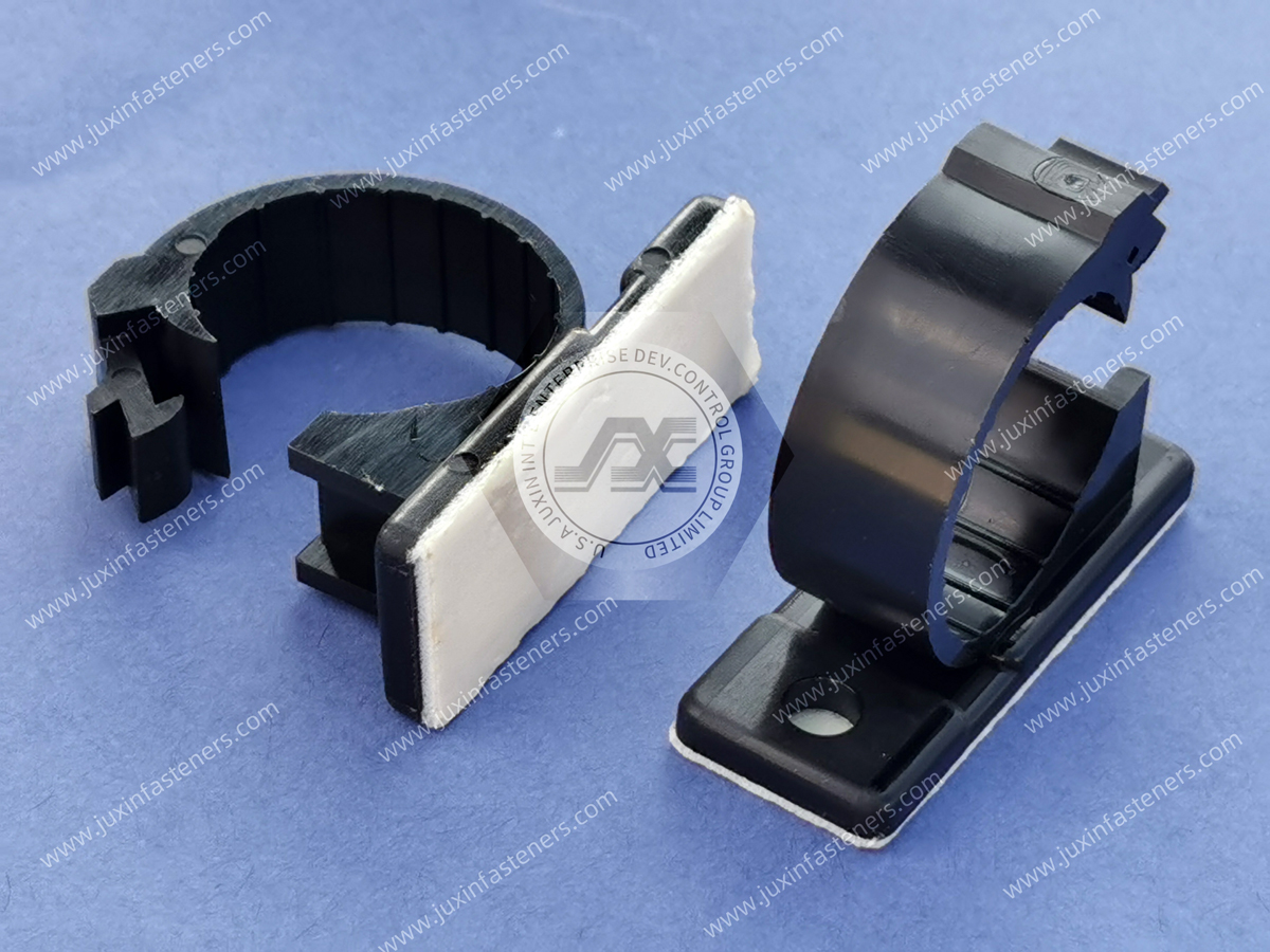
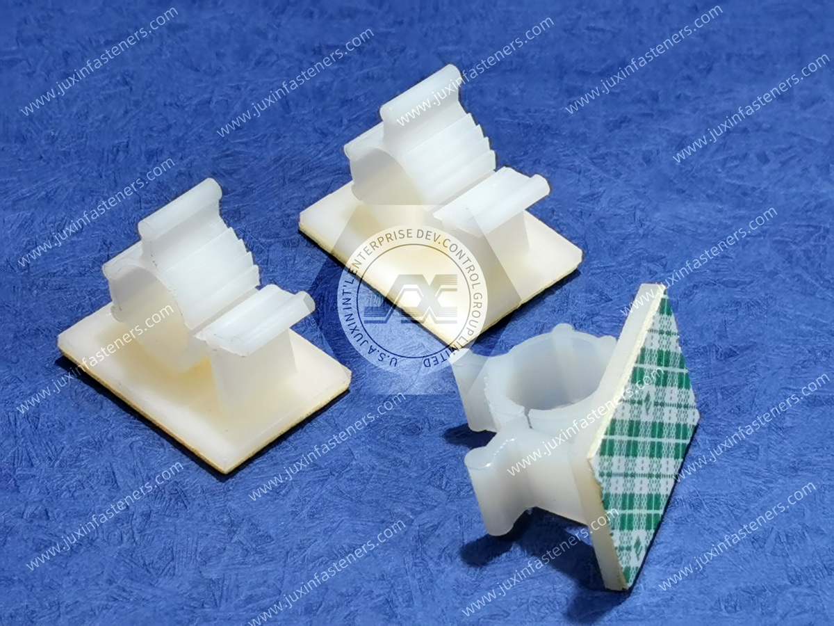
Cable ties and P-clips are both cable-management components, but they solve different problems.
A cable tie primarily consolidates multiple wires into a bundle.
A P-clip establishes a mechanical connection between that bundle and the supporting structure.
Conceptually:
Cable Tie → Bundle-to-Bundle Retention
P-Clip → Bundle-to-Structure Retention
In many industrial assemblies, both are used together.
Cable ties organize the harness while P-clips establish defined structural routing points.
See our Cable Tie Mounts solutions for additional bundle anchoring options.
A screw-mounted P-clip normally uses a machine screw, bolt, stud, or other mechanical fastener to attach the clamp to the supporting structure.
A snap-in cable clip may instead engage directly with a panel hole.
Therefore:
P-Clip = Mechanical Fastener Mounting
Snap-In Cable Clip = Panel-Hole Retention
The correct architecture depends on assembly speed, serviceability, mounting strength, available panel geometry, and installation access.
See our Nylon Cable Clips solutions for snap-in routing applications.
Standard nylon P-clips typically consist of:
curved retaining loop;
defined internal cable area;
molded band;
mounting foot;
fastener clearance hole.
When the mounting foot is secured, the loop retains the cable or harness at the intended location.
Standard configurations can be suitable for general electrical equipment, machinery, control cabinets, appliances, HVAC equipment, and other industrial assemblies.
Applications exposed to higher dynamic loading may require increased structural rigidity.
Heavy-duty configurations can incorporate:
thicker clamp bands;
wider bands;
reinforced mounting areas;
molded ribs;
increased material around the mounting hole;
application-specific loop geometry.
These features can improve structural capability, but a thicker clamp is not automatically the correct solution.
Increasing stiffness can also increase contact pressure on the cable and reduce the clamp's ability to accommodate harness variation.
The complete interface must therefore be evaluated.
Increasing clamp band width distributes contact over a larger section of the cable jacket or wire harness.
This can be beneficial where the retained bundle has a relatively soft outer jacket.
However:
Wider Band ≠ Automatically Better Retention
A wider clamp also occupies more packaging space and may interfere with:
connectors;
branches;
adjacent harnesses;
brackets;
enclosure walls.
Band width should therefore be selected according to both mechanical load and routing geometry.
One of the most common sourcing errors is assuming that:
Harness OD = Required Clamp ID
This is not always correct.
The effective harness diameter can change because of:
wire bundle tolerance;
cable jacket tolerance;
tape wrapping;
braided sleeving;
corrugated conduit;
heat-shrink tubing;
branch transitions;
production variation.
A nominal 10 mm electrical bundle may therefore not behave like a rigid 10 mm cylindrical shaft.
Engineering teams should evaluate the actual finished harness condition rather than relying only on the theoretical cable diameter.
An oversized nylon cable clamp can allow:
harness movement;
impact against the clamp;
fretting;
noise;
jacket abrasion;
shifting of the routing position.
In vibration-sensitive equipment, even small repeated relative movement can become important over a long service life.
Therefore:
Loose Fit → Relative Movement → Repeated Contact → Potential Chafing
The actual risk depends on cable construction, vibration, contact geometry, environment, and service duration.
An undersized clamp can apply excessive radial pressure to the retained bundle.
Potential consequences include:
cable jacket compression;
conductor deformation;
insulation damage;
restricted movement;
clamp overstress;
difficulty during assembly.
For flexible tubing, excessive compression can potentially reduce the internal flow area.
Therefore:
Tighter Fit ≠ Automatically Better Retention
The objective is controlled retention without damaging the routed component.
A wire harness is not always a dimensionally rigid cylinder.
A bundle of individual wires may compress significantly under clamp pressure, while a thick-wall power cable may compress very little.
This means two harnesses with the same measured outside diameter can require different clamp behavior.
For critical applications, engineers should consider:
cable construction;
insulation hardness;
bundle wrapping;
conductor arrangement;
required movement.
This is one reason physical sample validation is valuable during cable-clamp qualification.
The mounting hole in the P-clip foot must be compatible with the intended screw, bolt, or stud.
Important parameters include:
fastener nominal diameter;
actual shank diameter;
mounting-hole ID;
washer arrangement;
screw-head bearing diameter.
Excessively tight clearance can complicate assembly.
Excessive clearance can allow clamp movement before tightening.
Therefore:
Fastener Nominal Size ≠ Clamp Mounting-Hole Diameter
The actual drawing dimensions should govern.
The mounting foot transfers the harness load into the supporting structure.
Its geometry influences:
bearing area;
clamp orientation;
screw-head seating;
resistance to rotation;
local stress around the mounting hole.
A small mounting foot may fit compact spaces but provide less bearing area.
A larger foot can improve support but requires additional installation space.
Two cable clamps can have the same nominal loop diameter and still be incompatible.
Differences in:
hole center position;
foot length;
loop centerline;
overall height;
band width;
can move the wire harness away from its intended routing position.
This is especially important where the harness must maintain clearance from:
sharp edges;
hot surfaces;
rotating parts;
fans;
belts;
busbars;
connectors.
Therefore:
Same Clamp ID ≠ Same Harness Routing Geometry
This is a critical consideration in second-source qualification.
The mounting screw is normally metallic and may be capable of significantly higher tightening torque than the nylon clamp can tolerate.
This creates an important design rule:
Metal Screw Torque Capacity ≠ Allowable Plastic Clamp Assembly Torque
Excessive tightening can produce:
mounting-foot crushing;
local deformation;
hole elongation;
cracking;
long-term creep.
Installation torque must therefore be validated for the complete joint rather than copied from a general metal-to-metal torque table.
The screw head or washer transfers installation load into the plastic mounting foot.
A very small bearing area can create high local compressive stress.
Where appropriate, a compatible flat washer may help distribute the load.
However, washer OD must also be checked for interference with the clamp loop and surrounding equipment.
PA66 is widely used for molded cable-management components because suitable grades can provide a practical combination of:
strength;
toughness;
fatigue resistance;
electrical insulation;
moldability;
corrosion-free construction.
However:
PA66 is a material family, not a complete performance specification.
Actual properties depend on:
resin grade;
conditioning;
temperature;
additives;
geometry;
manufacturing conditions.
For demanding applications, material requirements should be specified at the project level.
Polyamide absorbs moisture from the environment.
Moisture conditioning can change:
stiffness;
toughness;
flexibility;
dimensions;
long-term mechanical response.
A dry-as-molded clamp can therefore behave differently from a moisture-conditioned clamp in service.
For tightly controlled retention applications, engineers should evaluate the expected operating condition rather than relying only on initial room-temperature properties.
Cable clamps installed near power electronics, motors, engines, inverters, transformers, power supplies, or other heat-generating components can experience elevated temperatures.
Long-term heat exposure can affect polymer mechanical properties.
Where temperature is significant, engineering teams should define:
normal operating temperature;
maximum continuous temperature;
short-term peak temperature;
thermal cycling profile.
Heat-stabilized resin grades may be appropriate for selected applications, but material selection should be based on the actual service environment.
Some electrical and electronic applications require a specified flammability classification.
Where UL 94 is required, the project should identify the necessary classification and applicable material thickness.
It is important to distinguish:
Base Polymer Type ≠ UL 94 Classification
and
One PA66 Grade ≠ Every PA66 Grade
Flammability performance depends on the specific resin formulation and tested thickness.
Juxin Fasteners can evaluate project-specific material requirements when they are included in the RFQ or drawing.
A P-clip in a vibrating machine experiences more than simple static cable weight.
Dynamic loading can be influenced by:
harness mass;
unsupported span;
vibration frequency;
vibration amplitude;
clamp spacing;
harness stiffness;
mounting orientation.
A longer unsupported harness span can increase dynamic movement and loading at the clamp.
Therefore:
Cable Clamp Selection ≠ Clamp Strength Alone
The routing architecture must also be considered.
If two mounting points are positioned too far apart, the cable between them can oscillate.
This can increase:
bending at the clamp exit;
cable movement;
clamp loading;
connector loading;
chafing risk.
Clamp spacing should therefore be defined as part of the complete wire-harness design.
The harness should ideally leave the clamp in a controlled direction.
A severe side angle immediately after the clamp can concentrate stress at the clamp edge.
This is especially relevant for:
stiff power cables;
shielded cables;
thick cable bundles.
Routing should therefore consider both the clamp location and the cable path immediately before and after the mounting point.
Cable abrasion is often attributed to the clamp, but the root cause can involve multiple interacting factors.
Potential contributors include:
incorrect clamp size;
excessive harness movement;
rough cable surface;
vibration;
contamination;
sharp adjacent edges;
insufficient routing clearance.
Therefore, a chafing investigation should evaluate:
Clamp + Harness + Routing + Vibration + Adjacent Structure
rather than replacing the clamp without identifying the actual cause.
A polymer cable clamp can provide a non-conductive interface between a cable bundle and a metallic mounting structure.
This may be useful where direct metallic contact is undesirable.
However:
Nylon P-Clip ≠ Complete Electrical System Isolation
The complete equipment design must still account for:
cable insulation;
fasteners;
grounding;
creepage;
clearance;
conductive contamination.
Polymer clamps do not create the same direct metal-to-metal contact path as an all-metal clamp body.
This can be useful around mixed-metal structures.
However, the metallic mounting screw may still contact the chassis.
Therefore, complete galvanic isolation should not be assumed from the clamp material alone.
Nylon wire harness clamps can support routing for:
body harnesses;
interior electrical systems;
lighting harnesses;
sensor wiring;
control modules;
selected underbody or compartment routing where the specified material is suitable.
Automotive projects should define project-specific:
temperature;
vibration;
chemical exposure;
material;
validation requirements.
A general-purpose nylon P-clip should not automatically be assumed suitable for every vehicle location.
Industrial machinery can contain extensive:
sensor cables;
motor cables;
control wiring;
pneumatic lines;
auxiliary tubing.
Screw-mounted cable clamps provide defined routing points on:
machine frames;
sheet-metal panels;
control enclosures;
moving equipment structures where appropriate.
Vibration and service access are particularly important in these applications.
Potential applications include routing within:
switchgear;
power distribution cabinets;
inverter systems;
power conversion equipment;
industrial electrical enclosures.
Material temperature capability and project-specific flammability requirements should be confirmed where applicable.
High-density AI computing infrastructure requires controlled routing of:
power cables;
control wiring;
monitoring cables;
fan and cooling-system wiring;
auxiliary harnesses.
Plastic cable clamps can be used in selected rack, power-distribution, cooling, and supporting equipment assemblies where the material and geometry meet the project requirements.
Selection should consider:
cable density;
service access;
airflow;
thermal environment;
vibration from cooling equipment.
Solar power equipment, energy storage systems, inverters, power conversion equipment, and related infrastructure can require organized routing of power and control cables.
Applications may involve:
internal enclosure routing;
sensor wiring;
control harnesses;
auxiliary cable management.
Outdoor applications require additional evaluation of UV exposure, moisture, temperature, and weathering.
HVAC systems contain:
fan wiring;
compressor wiring;
control harnesses;
sensor cables.
Vibration from motors, fans, and compressors can make positive cable retention important.
Clamp selection should consider both vibration and expected service access.
Medical and laboratory equipment may use cable clamps for internal routing where clean organization and controlled cable positioning are required.
Project-specific requirements relating to:
material;
cleaning chemicals;
temperature;
regulatory compliance;
must be defined by the equipment manufacturer.
Marine equipment introduces:
humidity;
salt exposure;
vibration;
temperature variation.
Polymer cable clamps can eliminate corrosion of the clamp body itself, but the mounting fastener and surrounding metallic interfaces still require appropriate material selection.
Agricultural and off-highway machinery can expose cable-management components to:
vibration;
shock;
dust;
moisture;
temperature variation.
Harness routing should be evaluated together with environmental protection and mechanical clearance.
Possible causes:
clamp ID too large;
harness OD smaller than expected;
compressible bundle;
insufficient routing support.
Possible contributors:
relative movement;
vibration;
clamp mismatch;
contamination;
adjacent structure contact.
Possible causes:
excessive installation torque;
insufficient bearing area;
misalignment;
impact loading;
unsuitable material condition.
Possible causes:
oversized harness;
excessive dynamic load;
high temperature;
incorrect geometry.
Possible causes:
excessive torque;
clamp rotation;
repeated dynamic load;
insufficient material around the hole.
Possible causes:
insufficient mounting preload;
oversized mounting hole;
low-friction mounting surface;
dynamic harness loading.
Possible causes:
clamp ID too small;
incorrect cable OD assumption;
soft cable jacket;
excessive clamp closure.
Potential contributors:
unsuitable material grade;
thermal aging;
UV exposure;
chemical exposure;
environmental conditions.
Failure analysis should evaluate the entire installation rather than the clamp as an isolated component.
A sourcing request may initially state:
“We need a 12 mm nylon P-clip.”
That does not establish interchangeability.
Two nominal 12 mm cable clamps can differ in:
actual closed-loop ID;
band width;
band thickness;
mounting-hole diameter;
mounting-foot length;
hole-center position;
overall height;
material;
geometry.
Even if both physically retain a 12 mm bundle, they may position the harness differently within the equipment.
Therefore:
Same Nominal Clamp Size ≠ Same Clamp Geometry ≠ Same Harness Routing Position
This is one of the most important considerations when qualifying a second source.
For engineering and procurement comparison, Juxin Fasteners recommends verifying at least:
Loop ID + Band Width + Band Thickness + Mounting Hole ID + Foot Length + Hole Center Position + Overall Height + Material
Where the geometry is more complex, the customer drawing should govern.
Additional application parameters should include:
Harness OD + Fastener Size + Temperature + Vibration + Environment
This provides a much stronger basis for interchangeability than nominal clamp size alone.
Provide:
manufacturer;
manufacturer part number;
OEM part number;
2D drawing;
3D CAD model;
physical sample;
photographs.
Confirm:
nominal bundle OD;
minimum OD;
maximum OD;
cable type;
jacket material if relevant;
sleeving or wrapping;
bundle weight.
Specify:
loop ID;
band width;
band thickness;
mounting-hole diameter;
foot geometry;
overall dimensions.
Provide:
screw or bolt size;
screw-head type;
washer arrangement;
mounting surface;
threaded hole, nut, or stud configuration.
Specify:
clamp orientation;
unsupported cable span;
nearby hot components;
moving components;
sharp edges;
required clearance.
Provide:
minimum temperature;
maximum temperature;
vibration;
shock;
humidity;
UV exposure;
chemical exposure;
indoor or outdoor use.
Specify where applicable:
PA66;
heat-stabilized grade;
UV-stabilized grade;
flame-retardant requirement;
other project-specific polymer.
Check:
harness fit;
mounting alignment;
loop closure;
cable compression;
assembly effort;
routing position.
Where required, evaluate:
vibration;
pull loading;
thermal cycling;
cable abrasion;
long-term retention;
serviceability.
After approval, proceed to:
quotation;
material confirmation;
inspection requirements;
packaging;
lot traceability;
production planning.
Standard P-clips cover many common cable-routing requirements, but proprietary equipment may require application-specific geometry.
Custom requirements can include:
non-standard loop ID;
wider clamp band;
reinforced mounting foot;
special mounting-hole diameter;
offset mounting foot;
unusual harness routing angle;
custom material;
application-specific profile.
Juxin Fasteners can support drawing-based custom cable-management components through:
2D drawing review;
3D CAD review;
physical sample comparison;
dimensional analysis;
material evaluation;
DFM discussion;
tooling evaluation;
sample validation;
production sourcing.
See our Custom Molded Plastic Fasteners solutions for proprietary OEM plastic components.
For faster engineering review and quotation, provide as much of the following information as possible.
manufacturer;
manufacturer part number;
OEM part number;
drawing;
CAD model;
physical sample;
photographs.
nominal OD;
minimum OD;
maximum OD;
cable construction;
sleeving or wrapping;
approximate harness weight.
loop ID;
band width;
band thickness;
mounting-hole ID;
mounting-foot dimensions;
overall height;
hole-center position.
screw / bolt size;
screw-head type;
washer;
chassis material;
mounting orientation.
static load;
vibration;
shock;
cable movement;
service frequency.
minimum temperature;
maximum temperature;
humidity;
UV exposure;
chemical exposure;
indoor / outdoor application.
PA66;
heat-stabilized grade;
UV-stabilized grade;
flame-retardant requirement where applicable;
other specified polymer.
sample quantity;
production quantity;
expected annual usage;
delivery schedule;
RoHS declaration;
REACH declaration;
material documentation;
lot traceability;
inspection requirements.
Providing the finished harness OD together with the clamp geometry, mounting interface, operating environment, and existing part information significantly improves second-source evaluation accuracy.
Related Juxin Fasteners product and engineering solutions include:
Adjustable Cable Clamps for variable bundle diameters;
Nylon Cable Clips for snap-in wire routing;
Cable Tie Mounts for anchored cable bundling;
Nylon Snap Bushings for cable protection through panel cutouts;
Strain Relief Bushings for controlling cable movement at enclosure entry points;
Custom Molded Plastic Fasteners for proprietary cable-management hardware.
These products perform different functions within the wire-management architecture and should be selected according to the actual harness,
mounting interface, environment, assembly process, and service requirements.
Juxin Fasteners supports automotive and commercial vehicle manufacturers, industrial automation companies, electrical equipment OEMs,
power-distribution manufacturers, machinery builders, renewable-energy equipment companies, AI data center infrastructure suppliers,
HVAC manufacturers, telecommunications equipment manufacturers, medical equipment companies, contract manufacturers, procurement teams,
and supplier-development organizations requiring standard or custom plastic cable-management hardware.
For nylon P-clip and heavy-duty cable clamp projects, the sourcing pathway can begin with:
Existing Part / Drawing / Sample → Harness OD Review → Clamp Geometry Review → Mounting Interface Review
→ Routing & Environment Review → Material Selection → Candidate Clamp → Physical Sample → Assembly & Functional Validation → Second-Source Qualification → Production RFQ
This process can support:
new product development;
wire harness routing;
cable-management redesign;
existing component replacement;
supplier consolidation;
second-source qualification;
obsolete component replacement;
custom cable clamp development.
Send us your existing supplier part number, OEM part number, 2D drawing, 3D CAD model, physical sample, harness diameter,
clamp dimensions, mounting-fastener information, temperature range, vibration requirements, material specification, compliance requirements, and expected annual volume for technical review.
Email: info@juxinfasteners.com
Website: www.juxinfasteners.com
Product Packaging
Packaging Standard
At Juxin Fasteners, we apply standardized export packaging to ensure product protection, traceability, and compliance with international logistics requirements.
1. Standard Export Packaging
Unless otherwise specified, all products will be packed according to our factory standard export packaging, which includes:
Moisture-resistant inner protection
Poly bag or small box packing as required
Reinforced export cartons
Clear labeling with part number, specification, batch number, and quantity
Palletizing for sea or air shipment when necessary
Our standard packaging is designed to ensure safe transportation, efficient warehousing, and long-distance international shipping.
2. Customized Packaging Options
We also provide customized packaging solutions according to customer requirements, including but not limited to:
Private labeling
Customized barcodes
Specific carton dimensions
Retail packaging
Special pallet configuration
Customer-specific marking and identification
So that you know, customized packaging may involve additional costs and extended lead time depending on the complexity of the requirements.
3. Compliance & Quality Assurance
All packaging processes are controlled under our ISO 9001 quality management system to ensure consistency, traceability, and product integrity throughout the supply chain.
Product Pictures
Contact Us
Tel.:
+86 020 8621 0320
+86 020 3121 6067
E-mail:
Technical Support:
Navigation
SEND INQUIREY