
Call Us
+86 136 6007 9809
Call Us
+86 136 6007 9809

Nov. 04, 2023
Selecting a precision dowel pin is only one part of designing an accurate locating system.
The performance of the assembly is determined by the relationship between the pin, hole and mating components.
A precision-ground dowel pin installed into an incorrectly specified hole can still produce excessive assembly force,
unwanted clearance, poor repeatability, component distortion or difficult maintenance.
For design engineers, the critical relationship is:
pin size and tolerance + hole size and tolerance + hole position + mating material + required joint function
This means there is no universal dowel pin hole tolerance that is correct for every application.
JUXIN FASTENERS manufactures precision dowel pins, cylindrical pins, parallel pins, hardened locating pins,
stainless steel dowel pins, pull-out dowel pins, oversized repair pins and custom precision pins for automotive,
industrial machinery, automation, robotics, tooling, electrical equipment and OEM manufacturing.
This guide explains how engineers should approach dowel pin fits, hole tolerances and locating-system design.
A dowel pin fit is created by the dimensional relationship between the pin and the mating hole.
It is not determined by nominal diameter alone.
For example, specifying an “8 mm dowel pin” does not fully define how that pin will assemble into an “8 mm hole.”
The actual relationship depends on:
Pin diameter tolerance
Hole diameter tolerance
Pin roundness
Hole geometry
Surface condition
Material
Temperature
Coating or finish where applicable
Manufacturing variation
The first engineering principle is therefore:
Nominal size does not define the fit. Tolerances define the fit.
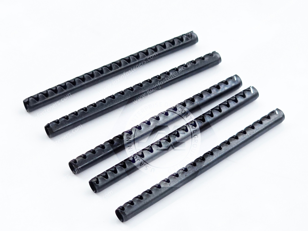
Dowel pins are frequently used where repeatable component location matters.
Typical applications include:
Machine housings
Gearboxes
Automotive components
CNC fixtures
Injection molds
Stamping dies
Robotic tooling
Automation equipment
Inspection fixtures
Precision assemblies
If the hole is too large relative to the pin, the assembly may lose the required locating control.
If the hole is too small, installation force may become excessive.
The correct hole is therefore not simply the tightest hole that can be manufactured.
It is the hole that creates the required functional fit.
Before specifying tolerances, determine what the pin must accomplish.
Ask:
Is the pin primarily locating the components?
Must the pin remain permanently in one component?
Must the mating component be removable?
Is repeated assembly required?
Will the pin transfer shear load?
Is the pin used as a manufacturing datum?
Is field maintenance expected?
Are multiple pins locating the same component?
The answers determine the appropriate fit strategy.
A press fit, or interference fit, is created when the dimensional relationship between the pin and hole produces interference.
This may be useful where the dowel pin must remain retained in one component.
Potential applications include:
Machine housings
Tooling
Fixtures
Mold components
Automotive assemblies
Industrial equipment
However:
More interference does not automatically mean a better joint.
Excessive interference can cause:
Excessive insertion force
Hole expansion
Pin surface damage
Component distortion
Cracking in unsuitable materials
Difficult removal
Loss of dimensional accuracy
The interference should be selected for the actual component design.
A slip or controlled clearance fit may be used where a component must assemble over a locating pin and later be removed.
Typical applications include:
Removable covers
Tooling plates
Inspection fixtures
Changeover tooling
Machine modules
Serviceable equipment
The engineering challenge is balancing two competing requirements:
easy assembly
and
accurate location
Too little clearance may make assembly difficult.
Too much clearance may reduce positional repeatability.
A transition fit occupies the dimensional region between definite clearance and definite interference.
Depending on actual manufactured dimensions, individual assemblies may produce slight clearance or slight interference.
Transition-fit concepts can be useful in selected locating applications, but they must be evaluated through the complete tolerance stack.
The words “transition fit” alone are not sufficient to manufacture the joint.
The drawing still needs actual dimensional requirements.
One of the most useful approaches for serviceable precision assemblies is to design the pin to remain fixed in one component while the second component locates over it.
Conceptually:
Base component → retained pin
Removable component → locating hole
This allows the dowel pin to establish location without requiring both components to grip the pin tightly.
This strategy can improve:
Assembly efficiency
Maintenance
Repeatable positioning
Component replacement
Pin retention
The exact fits must still be determined from the application.
Engineers should avoid evaluating the dowel pin as an isolated component.
The locating system includes:
Pin
Retaining hole
Mating hole
Component geometry
Hole spacing
Positional tolerances
Clamping fasteners
Assembly sequence
A high-precision pin cannot correct inaccurate mating components.
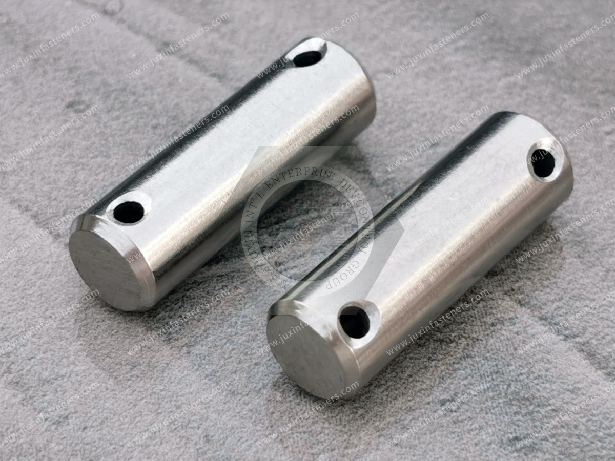
A hole can have the correct diameter and still be in the wrong position.
This distinction becomes particularly important when two or more dowel pins are used.
Consider two mating components containing two locating holes.
Even if all four holes meet their diameter tolerances, assembly may become difficult if the center-to-center position differs between the components.
Possible consequences include:
Binding
Forced assembly
Internal stress
Distortion
Difficult maintenance
Loss of repeatability
For this reason, engineers should consider GD&T and positional tolerance, not only hole diameter.
Using two precision dowel pins can accurately constrain a component.
But if both pins and both mating holes are specified too tightly without considering positional variation, the design can become over-constrained.
Manufacturing variation then makes assembly difficult.
The correct locating strategy depends on:
Required degrees of freedom
Component size
Hole spacing
Manufacturing capability
Required repeatability
Thermal expansion
Assembly process
Precision design means controlling the necessary movement—not simply eliminating every possible clearance.
In precision fixtures and tooling, designers sometimes use locating strategies that constrain the required directions without unnecessarily constraining every direction at every locating point.
The exact design depends on the application and engineering standard.
The underlying principle is important:
Locate the component accurately without creating unnecessary redundant constraint.
This becomes increasingly important as:
Distance between locating points increases
Component size increases
Temperature variation increases
Positional tolerances become tighter
The hole-manufacturing process should be capable of achieving the required tolerance and geometry.
Possible processes include:
Drilling
Reaming
Boring
CNC machining
Grinding or specialized finishing
Drilling alone may be adequate for some general applications.
Precision locating systems may require additional finishing operations.
The process should be selected according to:
Hole tolerance
Surface requirement
Material
Production volume
Required repeatability
Manufacturing capability
No.
Reaming is commonly used for precision dowel holes because it can improve dimensional control compared with basic drilling.
However, saying that every dowel pin hole must be reamed would be incorrect.
The correct manufacturing process depends on the required fit and manufacturing capability.
The drawing should specify the functional requirement rather than assume one production process unless that process is itself required.
Diameter tolerance alone does not describe the complete mating surface.
Surface condition can influence:
Installation force
Contact behavior
Wear
Galling
Removal
Repeatability
For precision or high-cycle applications, surface requirements may therefore be relevant to the locating system.
A correctly machined hole with a burr at its entrance can behave like an incorrectly sized hole during installation.
Potential effects include:
Increased insertion force
Scratching
Pin damage
Misalignment
Incomplete seating
Hole entrance condition should therefore be controlled during production.
Many precision pins incorporate end geometry that assists installation.
A suitable pin chamfer or hole lead-in can help:
Guide the pin
Reduce edge interference
Improve assembly consistency
Protect mating surfaces
However, excessive chamfering can reduce the effective locating contact area.
The geometry should be appropriate for the joint.
The same nominal interference can behave differently depending on the mating material.
A hardened steel housing and an aluminum housing do not respond identically.
Important material properties include:
Elastic modulus
Yield strength
Hardness
Wall thickness
Thermal expansion
Galling tendency
Surface condition
Therefore, dowel pin fits should not be copied blindly from one assembly into another made from different materials.
Hardened steel dowel pins are commonly selected where the application requires:
Wear resistance
Dimensional stability
Precision location
Mechanical strength
Typical applications include:
Machinery
Tooling
Fixtures
Dies
Industrial equipment
The mating component still requires a compatible fit and material design.
Stainless steel locating pins may be selected for applications requiring corrosion resistance.
Possible materials depend on the required combination of:
Corrosion resistance
Hardness
Strength
Wear resistance
Temperature
304, 316 and martensitic stainless grades should not be treated as interchangeable materials.
Each provides a different engineering balance.
Aluminum housings are common in:
Automotive systems
EV equipment
Electronics
Robotics
Automation
Lightweight machinery
When using a steel or stainless steel pin in aluminum, engineers should consider:
Local deformation
Hole wear
Wall thickness
Repeated removal
Thermal expansion difference
Corrosion interaction
Operating temperature
A fit used successfully in steel should not automatically be transferred to aluminum.
Pressing a pin into a thin wall can produce local deformation even when the nominal interference appears reasonable.
Potential consequences include:
Hole expansion
Wall distortion
Cracking
Loss of surrounding dimensional accuracy
The surrounding component geometry is therefore part of the fit calculation.
Temperature changes dimensions.
When the pin and mating component are made from different materials, they may expand and contract at different rates.
This can change:
Clearance
Interference
Retention
Assembly force
Removal force
Stress
Thermal effects may be important in:
Automotive systems
Power equipment
EV components
Industrial machinery
Outdoor equipment
High-temperature assemblies
Precision equipment
The relevant temperature range should be included in the engineering review where necessary.
Surface treatments may change the final dimensional condition of a precision component.
For close-tolerance pins, the manufacturing and finishing sequence should therefore consider whether the specified final dimension applies before or after finishing.
Possible treatments include:
Black oxide
Zinc-based coatings
Nickel coatings
Passivation
Application-specific protective finishes
Not every finish is appropriate for every precision pin or fit.
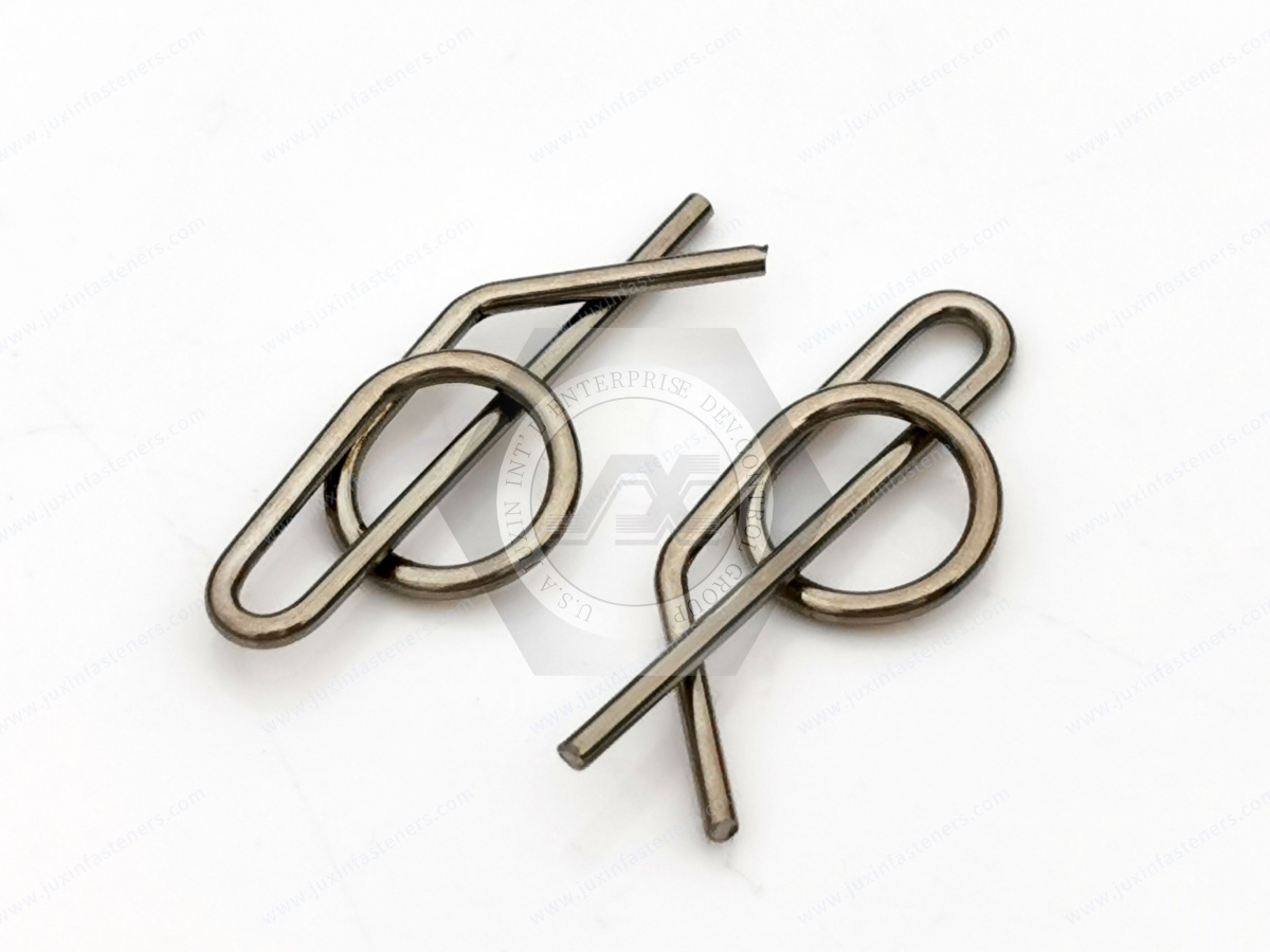
Retaining compounds may be used in some assemblies.
However, adhesive should not automatically be used to compensate for:
Incorrect hole size
Poor positional accuracy
Excessive wear
Wrong pin selection
If a retaining compound is part of the design, the joint should be engineered and validated accordingly.
A useful way to evaluate a locating system is to consider all dimensional contributors.
These may include:
Pin diameter
Pin tolerance
Retaining-hole diameter
Retaining-hole tolerance
Mating-hole diameter
Mating-hole tolerance
Hole position
Hole spacing
Component machining tolerances
Thermal variation
Looking only at one tolerance can hide the actual source of assembly variation.
For tolerance analysis, engineers may need to consider the dimensional extremes of the pin and hole.
The tightest possible manufactured combination may determine maximum interference.
The loosest possible combination may determine maximum clearance.
Both ends of the tolerance range matter.
A design that works only at nominal dimensions is not a robust production design.
If a component must be removed regularly, the fit strategy should account for:
Removal force
Hole wear
Surface damage
Repeatable location
Maintenance tools
Pin replacement
A permanently pressed locating system may not be the best choice for a frequently serviced assembly.
Internally threaded pull-out dowel pins are useful where the pin must be extracted from a blind or tightly fitted hole.
Applications include:
Molds
Dies
Fixtures
Machine assemblies
Automation tooling
The internal thread provides an extraction interface.
It should not be confused with the primary locating function of the cylindrical surface.
A worn locating hole can cause:
Positioning error
Loose fit
Movement
Reduced repeatability
An oversized repair pin can sometimes be used after the hole has been correctly reworked.
The correct repair sequence is:
inspect → restore hole geometry → establish new controlled dimension → select matching repair pin → validate location
Simply installing a larger pin into an irregular worn hole is not a precision repair.
Possible causes:
Hole undersize
Pin oversize
Burr
Contamination
Excessive interference
Misalignment
Surface damage
Possible causes:
Hole oversize
Pin undersize
Wear
Incorrect tolerance
Wrong standard or part
Material deformation
Possible causes:
Hole positional error
Incorrect hole spacing
Excessively tight clearance
Pin misalignment
Component distortion
Thermal effects
Possible causes:
Excessive mating-hole clearance
Hole wear
Damaged locating surfaces
Contamination
Incorrect locating strategy
Root-cause analysis should evaluate the complete joint.
Automotive dowel pins may be used in:
Machined housings
Transmission-related components
Production tooling
Welding fixtures
Inspection fixtures
Assembly equipment
The appropriate fit depends on whether the pin is used in the vehicle component itself or in manufacturing equipment.
These are different engineering environments and should not automatically use the same fit strategy.
Automation equipment often requires components to be removed and returned to a repeatable location.
Applications include:
Robot tooling
Fixture plates
Assembly modules
Inspection stations
Changeover tooling
A fixed-pin/removable-component strategy can be useful where serviceability and repeatability must coexist.
Molds and dies require accurate alignment over repeated production cycles.
Engineers should consider:
Wear
Extraction
Maintenance
Plate alignment
Replacement
Thermal conditions
Pull-out dowel pins or other serviceable locating designs may be appropriate depending on the tooling system.
Precision machinery may use dowel pins to locate:
Housings
Machine modules
Fixture components
Tooling
Guide structures
The required tolerance should be derived from machine geometry and functional accuracy rather than selected from a generic fit table without context.
Before releasing a dowel-pin drawing or assembly drawing, verify that the required information is defined.
Include where applicable:
Applicable standard
Nominal diameter
Diameter tolerance
Length
Material
Hardness
Surface finish
Surface treatment
Pin-end geometry
Retaining-hole size and tolerance
Mating-hole size and tolerance
Hole positional tolerance
Installation depth
Projection
Extraction feature
Special inspection requirements
The objective is to remove ambiguity before the component reaches production.
For efficient engineering review and quotation, provide:
2D drawing
3D model where available
Applicable ISO, DIN or ASME/ANSI specification
Pin diameter
Diameter tolerance
Length
Material
Heat treatment
Hardness
Surface finish
Surface treatment
End geometry
Extraction thread if required
Mating-hole information where relevant
Mating material
Required fit
Operating temperature
Corrosion environment
Application
Prototype quantity
Production quantity
Estimated annual volume
Inspection requirements
Material documentation requirements
For custom precision pins, the mating-component information can be particularly useful during manufacturability review.
There is no universal hole size based only on nominal pin diameter.
The correct hole depends on pin tolerance, required fit, mating material, locating strategy and applicable specification.
Not necessarily.
In many serviceable locating systems, the pin may be retained in one component while the second component uses a controlled removable fit.
Not automatically.
Accuracy depends on the complete locating system, including pin tolerance, hole tolerance, hole position, component geometry and clearance.
The tightest possible fit is not always the most appropriate design.
There is no universal interference value suitable for every assembly.
Pin diameter, mating material, wall thickness, pin length, installation method and functional requirements all affect the decision.
It should not be assumed.
The materials have different mechanical and thermal properties, which can change the behavior of the joint.
Common causes include positional error, incorrect center distance, excessive fit tightness, component distortion and tolerance accumulation.
If the pins establish precision location—especially when multiple locating points are used—hole position can be critical.
The required tolerance should come from the functional assembly requirement.
Potentially, but the hole should first be evaluated and reworked into a controlled geometry appropriate for the repair pin.
An oversized pin alone does not correct an irregular worn hole.
A reliable dowel pin joint begins with the locating strategy, not with a catalog diameter.
For design engineers, the decision path is:
joint function → pin standard → pin tolerance → hole tolerance → positional tolerance → material → fit → assembly → serviceability → validation
For purchasing and supplier-development teams, the sourcing path is:
drawing → specification → manufacturing review → sample → fit validation → inspection approval → production
JUXIN FASTENERS manufactures precision dowel pins, ISO-standard cylindrical pins, hardened locating pins, stainless steel dowel pins,
pull-out dowel pins, oversized repair pins and custom machined pins for automotive, industrial machinery, robotics, automation, tooling and global OEM manufacturing.
For related engineering information, see our guides to Precision Dowel Pins, ISO 8734 Cylindrical Pins, Spring Pins vs Dowel Pins, and Dowel Pin Installation & Assembly.
Send us your 2D drawing, 3D model, sample and mating-component requirements for engineering review and quotation.
JUXIN FASTENERS
FASTENING SOLUTIONS FOR GLOBAL OEMS
Website: www.juxinfasteners.com
Email: info@juxinfasteners.com
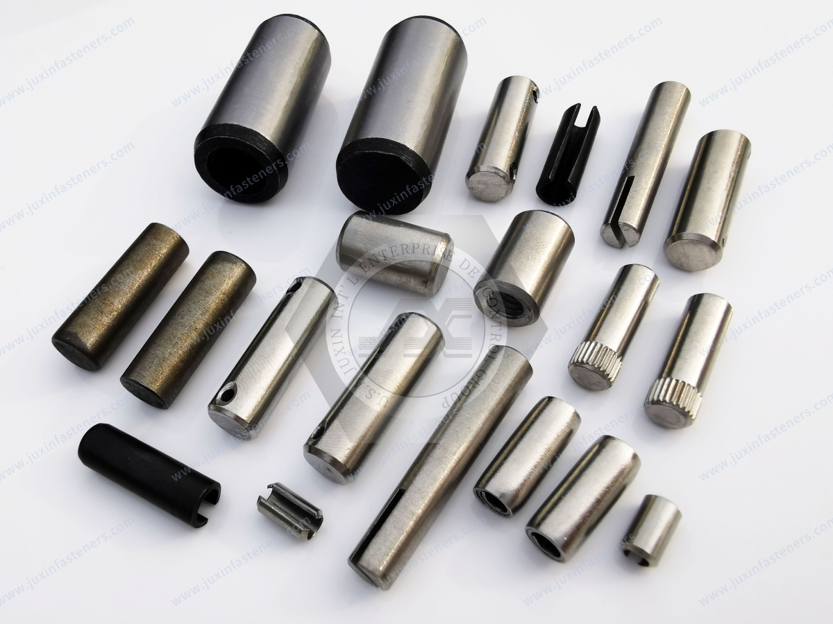
 MORE NEWS

Sep. 27, 2026

Sep. 27, 2026

Sep. 27, 2026
Contact Us
Tel.:
+86 020 8621 0320
+86 020 3121 6067
E-mail:
Technical Support:
Navigation
SEND INQUIREY