
Call Us
+86 136 6007 9809
Call Us
+86 136 6007 9809

Nov. 04, 2023
Installing a dowel pin looks simple: prepare a hole, align the pin and press it into position.
In precision mechanical assemblies, however, reliable dowel pin installation depends on much more than pin diameter alone.
The actual result is controlled by the complete locating system:
pin tolerance + hole tolerance + hole position + fit strategy + mating material + surface condition + installation method + operating environment
An incorrectly designed fit can create excessive insertion force, damaged holes, distorted components, poor positional accuracy or difficult maintenance.
Excessive clearance can create a different set of problems, including loss of repeatable location and unwanted movement.
For this reason, engineers should design the pin and mating holes as one locating system.
JUXIN FASTENERS manufactures precision dowel pins, cylindrical pins, parallel pins, hardened locating pins,
stainless steel dowel pins, internally threaded pull-out dowel pins, oversized repair pins and custom precision pins for automotive,
industrial machinery, automation, robotics, tooling, electrical equipment and OEM manufacturing.
This engineering guide explains how to select the fit, prepare the hole, install the pin and evaluate the completed assembly.
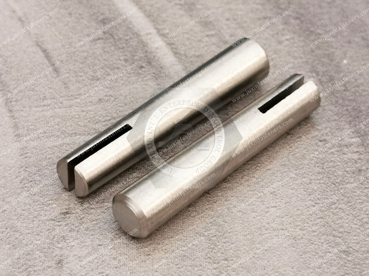
A dowel pin is a precision cylindrical component used primarily to establish controlled relative position between mating parts.
Common industry terminology includes:
Dowel pin
Cylindrical pin
Parallel pin
Locating pin
Alignment pin
Precision pin
Depending on the design, dowel pins may also participate in shear-load transfer.
Their main engineering value, however, is often repeatable mechanical location.
Typical applications include:
Machine housings
Gearboxes
Automotive assemblies
CNC fixtures
Injection molds
Stamping dies
Automation equipment
Robotic systems
Inspection fixtures
Precision mechanical assemblies
Unlike a bolt, whose primary purpose is normally to generate clamp load, a dowel pin is frequently used to establish position.
Understanding this difference is essential when designing the joint.
Internationally recognized pin specifications include several different cylindrical and parallel pin families.
Examples include:
ISO 8734 hardened parallel pins
ISO 2338 parallel pins
ISO 8735 internally threaded hardened parallel pins
Other DIN, ISO, ASME/ANSI or customer-specific pin configurations
A standard number should not be selected only because two products appear geometrically similar.
The applicable standard can define differences in:
Material
Hardness
Diameter tolerance
End geometry
Surface requirements
Threaded extraction features
Other dimensional characteristics
For drawing-controlled OEM projects, the customer drawing remains the primary source for the required geometry and performance.
Before determining hole size or installation method, identify the function of the pin.
Is the pin required to:
Precisely locate two components?
Maintain repeatable alignment after service?
Carry shear load?
Prevent lateral movement?
Position tooling?
Establish a manufacturing datum?
Remain permanently installed?
Be removed during maintenance?
These functions can require different fit strategies.
There is no universal “correct dowel pin fit” for every assembly.
One of the most useful concepts in dowel-pin assembly is to distinguish between the retaining side and the mating side.
In many serviceable assemblies, the designer may want the pin to remain fixed in one component while the second component can be removed and reinstalled.
Conceptually:
Component A → retains the dowel pin
Component B → locates over the dowel pin
This can be more practical than creating a tight interference condition through both components.
The actual fit and tolerances must still be selected according to the drawing, materials, pin specification and positional requirements.
This design approach can improve:
Assembly
Maintenance
Repeatability
Pin retention
Component replacement
Three general fit concepts are commonly discussed in precision pin assemblies.
An interference fit is used where the pin must be retained securely in the mating component.
The pin is larger than the corresponding hole within the designed tolerance relationship.
Installation therefore requires controlled force or another validated assembly process.
Potential uses include:
Permanently retained locating pins
Tooling
Machine components
Fixtures
Housings
Too much interference can create:
Excessive installation force
Hole expansion
Component distortion
Surface damage
Pin damage
Cracking in unsuitable materials
Interference should therefore be engineered rather than maximized.
A transition fit lies between clear clearance and definite interference.
Depending on the actual manufactured pin and hole dimensions, the assembly may produce slight clearance or slight interference.
This can be useful in certain locating applications where designers require controlled positioning without an excessively tight press condition.
The correct fit must be determined from the actual tolerance system.
A controlled clearance fit allows the mating component to assemble over the dowel pin without requiring a press fit.
It may be used on the removable side of a locating assembly.
Potential advantages include:
Easier assembly
Easier disassembly
Serviceability
Reduced risk of damaging the removable component
But excessive clearance can reduce locating accuracy.
The engineering objective is therefore not simply “make the hole larger.”
It is to provide the required assembly clearance while maintaining the required positional accuracy.
A common design mistake is specifying a precision pin while giving insufficient attention to the hole.
The fit is created by two manufactured features:
PIN + HOLE
A precision-ground pin cannot compensate for an incorrectly sized or poorly positioned mating hole.
Engineers should evaluate:
Nominal pin diameter
Pin diameter tolerance
Hole diameter
Hole diameter tolerance
Hole roundness
Hole cylindricity where relevant
Surface condition
Hole position
Mating material
This is especially important when multiple dowel pins locate the same component.
Imagine two perfectly manufactured dowel pins and two perfectly sized holes.
If the center-to-center position of the holes is incorrect, the assembly may still fail.
Possible results include:
Difficult assembly
Binding
Forced installation
Component distortion
Internal stress
Loss of locating accuracy
This is why dowel-pin design is also a GD&T and positional-control problem, not merely a diameter-tolerance problem.
For multi-pin locating systems, engineers should evaluate the complete tolerance stack.
Using multiple tight locating features without considering tolerance accumulation can over-constrain an assembly.
For example, two precision pins installed into two tightly controlled mating holes may become difficult to assemble if the positional tolerances are not compatible.
Depending on the application, engineers may use different locating strategies to control the required degrees of freedom without creating unnecessary constraint.
The correct solution depends on:
Component geometry
Required accuracy
Manufacturing capability
Thermal behavior
Assembly sequence
Service requirements
This is an important consideration in precision fixtures, machine assemblies and tooling systems.
Before preparing the hole, confirm:
Standard or drawing number
Nominal diameter
Diameter tolerance
Length
Material
Hardness
End geometry
Surface condition
Coating or finish
Extraction feature if applicable
Do not assume that all pins with the same nominal diameter have the same tolerance.
Determine whether the pin must be:
Permanently retained
Removable
Fixed in one component
Free in the mating component
Used for precision location
Used partly for shear-load transfer
Only then should the hole tolerance be finalized.
The required manufacturing process depends on the tolerance, material and production volume.
Processes can include:
Drilling
Reaming
Boring
Precision machining
Grinding or other finishing methods for specialized applications
A drilled hole alone may not provide the dimensional accuracy, roundness or surface condition required for a precision locating fit.
Reaming is commonly considered when tighter hole control is required, but the correct process should be selected according to the drawing requirements and manufacturing capability.
A suitable entrance feature can help guide the pin into the hole during installation.
Depending on the design, this may involve:
Chamfer
Lead-in
Radiused entrance
Pin-end chamfer
The entrance geometry should assist assembly without removing excessive locating engagement.
Sharp burrs at the hole entrance should be removed.
Before installation, inspect both components.
Remove:
Chips
Grinding debris
Dirt
Rust
Burrs
Foreign material
Contamination can affect insertion force, damage surfaces and alter the effective fit.
Precision assembly requires clean mating surfaces.
The pin should enter the hole as close to the intended axis as practical.
Misaligned pressing can cause:
Edge loading
Scratching
Pin deformation
Hole damage
Bent pins
Component damage
Appropriate installation tooling should support axial insertion.
For an interference-fit pin, force should be applied in a controlled manner.
Depending on the component and production environment, suitable equipment may include:
Arbor press
Mechanical press
Pneumatic press
Servo press
Hydraulic press
Dedicated assembly fixture
The correct equipment is determined by the required installation force, production volume, component sensitivity and process-control requirements.
A hydraulic press is therefore not automatically required for every dowel pin.
Manual impact installation may be used in some non-critical applications, but uncontrolled hammering can create problems in precision assemblies.
Risks include:
Pin-end damage
Surface damage
Misalignment
Uneven installation depth
Component marking
Uncontrolled installation force
For controlled OEM production, a guided installation process generally provides better repeatability.
In high-volume or safety-relevant manufacturing, insertion force can become useful process data.
Unexpectedly high force may indicate:
Undersized hole
Burr
Contamination
Misalignment
Incorrect pin
Surface damage
Unexpectedly low force may indicate:
Oversized hole
Incorrect pin diameter
Worn tooling
Incorrect machining
Insufficient interference
Where appropriate, force-displacement monitoring can help detect assembly variation before the product moves downstream.
A longer pin is not automatically a better pin.
The required engagement should be determined from the joint design.
Excessive engagement can:
Increase installation force
Increase removal difficulty
Add unnecessary material
Complicate blind-hole installation
Insufficient engagement can reduce the effective locating or load-transfer area.
Engineers should evaluate the required function rather than use a universal engagement rule.
Blind holes require additional consideration because trapped air, oil or other fluid may resist pin insertion.
Potential issues include:
Hydraulic pressure
Incomplete seating
Unexpected insertion force
Difficult removal
The hole and pin design should therefore consider venting, extraction and assembly requirements where applicable.
For assemblies requiring future removal, an internally threaded pull-out dowel pin may be a more serviceable solution.
Internally threaded dowel pins provide an extraction feature that allows tooling or a threaded puller to assist removal.
They are particularly useful in:
Injection molds
Dies
Fixtures
Tooling
Machine assemblies
Automation equipment
The threaded feature is not primarily there to fasten the pin.
Its main purpose can be to improve serviceability and extraction.
During long-term equipment operation, a locating hole may become:
Worn
Enlarged
Damaged
Out of tolerance
In some repair strategies, an oversized dowel pin may allow the locating system to be restored after the hole is reworked to a controlled repair dimension.
This can be relevant to:
Mold repair
Fixture rebuilding
Machine refurbishment
Maintenance operations
However, installing a larger pin directly into a worn hole without restoring the hole geometry does not automatically restore positioning accuracy.
The repair must treat the hole and pin as a new controlled fit system.
The same interference condition can behave differently in different mating materials.
Examples include:
Hardened steel housing
Mild steel plate
Stainless steel
Aluminum
Cast iron
Engineering alloys
The designer should consider:
Elastic modulus
Yield strength
Wall thickness
Hardness
Thermal expansion
Galling tendency
Surface condition
A fit appropriate for a thick steel component may not be appropriate for a thin aluminum wall.
Aluminum housings are common in automotive, EV, automation and lightweight industrial equipment.
When a hardened steel dowel pin is installed into aluminum, engineers should consider:
Local hole deformation
Material strength
Repeated removal
Thermal expansion difference
Fretting or wear
Corrosion compatibility
The hole design should therefore be validated for the actual aluminum alloy and operating environment.
Stainless steel pins may be selected for corrosion-resistant applications, but stainless material does not eliminate fit considerations.
Engineers should still evaluate:
Material grade
Hardness
Surface finish
Galling risk
Mating material
Environment
Installation force
“Stainless steel” alone is not a complete pin specification.
Pin and hole dimensions change with temperature.
If the pin and housing use different materials, their coefficients of thermal expansion may differ.
This can affect:
Installation
Retention
Operating clearance
Removal
Stress in the joint
Thermal effects deserve particular attention in:
Automotive powertrain equipment
EV systems
Industrial machinery
High-temperature equipment
Outdoor equipment
Precision instrumentation
The required analysis depends on the operating temperature range and materials.
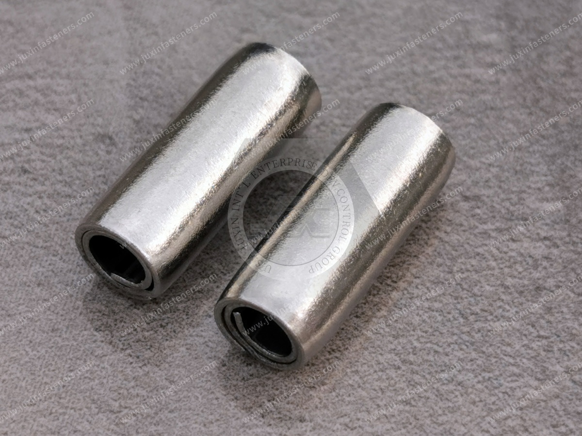
Controlled thermal assembly can be used in certain engineered interference-fit systems.
For example, temperature differences may temporarily alter the dimensions of the pin or mating component to assist installation.
However, thermal assembly should not be improvised.
Engineers must consider:
Material properties
Heat treatment
Coatings
Maximum permissible temperature
Condensation
Final interference
Component distortion
The assembly method should be validated as part of the manufacturing process.
Lubrication requirements depend on the material, finish, fit and assembly specification.
A lubricant can change:
Insertion force
Friction
Surface behavior
Final assembly conditions
Therefore, lubricant should not be added or omitted arbitrarily in a controlled production process.
Where lubrication is specified, its type and application method should be controlled.
Possible causes include:
Hole too small
Excessive interference
Burrs
Contamination
Misalignment
Incorrect pin diameter
Hole distortion
Do not automatically increase pressing force before identifying the cause.
Possible causes include:
Oversized hole
Undersized pin
Incorrect tolerance specification
Hole wear
Wrong pin standard
Incorrect machining process
Measure both the pin and hole before deciding on corrective action.
Possible causes include:
Hole positional error
Incorrect center distance
Excessively tight mating fit
Pin misalignment
Component distortion
Accumulated tolerance error
This is often a locating-system problem rather than a pin-quality problem.
Possible causes can include:
Inadequate retention
Hole wear
Incorrect fit
Cyclic loading
Material deformation
Thermal cycling
The root cause should be identified before simply replacing the pin.
Possible causes include:
Interference fit
Corrosion
Galling
Contamination
No extraction feature
Component deformation
If maintenance is expected, serviceability should be designed into the original joint.
Depending on application requirements, inspection may include:
Pin projection height
Installation depth
Perpendicularity
Component position
Hole position
Runout
Assembly alignment
Insertion force data
Visual surface condition
For precision tooling and machine assemblies, the final component relationship may be more important than checking the pin alone.
For OEM sourcing, useful inspection characteristics can include:
Diameter
Length
Roundness
Straightness
Surface roughness where specified
Hardness
Material
End geometry
Thread feature for pull-out pins
Surface treatment
Inspection requirements should correspond to the drawing and actual function.
Not every pin requires every possible test.
Automotive applications can include:
Machined housing alignment
Transmission-related components
Production fixtures
Welding fixtures
Inspection tooling
Assembly equipment
EV manufacturing equipment
Pin selection depends on the specific joint and validation requirements.
Precision pins are widely used to locate:
Fixture plates
Robot tooling
Assembly stations
Machine modules
Inspection equipment
Changeover tooling
Repeatable location can reduce setup variation when components are removed and reinstalled.
Molds and dies often require accurate component location throughout repeated production cycles.
Applications include:
Mold plates
Inserts
Die sections
Tooling plates
Replaceable components
Serviceable tooling may benefit from extraction features such as internally threaded pull-out pins.
Machine assemblies can use precision locating pins for:
Housing alignment
Fixture location
Machine modules
Guide components
Tooling systems
Correct pin fit helps maintain the intended geometric relationship between components.
Before releasing a drawing, confirm:
What is the pin's primary function?
Which component retains the pin?
Which component must be removable?
What pin standard or drawing applies?
What is the pin diameter tolerance?
What is the hole tolerance?
Is the fit interference, transition or clearance?
Are hole positional tolerances defined?
Is the assembly over-constrained?
What are the mating materials?
Is temperature relevant?
Is corrosion relevant?
How will the pin be installed?
How will the pin be removed?
Is an extraction thread required?
What inspection is required after assembly?
This checklist can prevent many problems before production begins.
For an efficient OEM quotation, provide:
2D drawing
3D model where available
Applicable ISO, DIN or ASME/ANSI standard
Pin diameter
Length
Diameter tolerance
Material
Hardness requirement
Surface finish
Surface treatment
End geometry
Threaded extraction feature if required
Mating-hole information where relevant
Mating material
Fit requirement
Operating temperature
Corrosion environment
Application description
Prototype quantity
Production quantity
Estimated annual volume
Inspection requirements
Material or inspection documentation requirements
The more clearly the joint requirements are defined, the easier it is to evaluate manufacturability and quotation accurately.
Not always.
A press or interference fit may be appropriate when the pin must remain retained in one component, while the mating component may use a different fit.
The correct design depends on the assembly function.
There is no single universal hole size based only on nominal pin diameter.
The correct hole depends on the pin tolerance, required fit, mating material, applicable standard and assembly requirements.
Reaming is commonly used when the required hole accuracy cannot be achieved reliably by drilling alone.
However, the manufacturing process should be selected according to the specified hole tolerance, surface requirement and production method.
Uncontrolled impact can damage the pin or mating component in precision applications.
A guided and controlled installation method is generally preferable where assembly accuracy and repeatability matter.
This depends on the pin, fit, hole condition and application requirements.
For serviceable assemblies, removal should be considered during design rather than after the pin has been installed.
A pull-out dowel pin includes an internal threaded feature or other extraction provision that assists removal from blind or tightly fitted installations.
An oversized dowel pin is a repair or special pin with a diameter larger than the original nominal configuration.
It may be used with a properly reworked hole to restore a controlled locating system.
The problem may be caused by center-distance error, hole positional tolerance, pin misalignment, fit selection or tolerance accumulation.
Pin diameter alone may not be the root cause.
Successful dowel pin installation starts long before the pin reaches the assembly line.
The correct engineering sequence is:
joint function → locating strategy → pin specification → material → hole tolerance → positional tolerance → fit → installation → inspection → serviceability
For procurement teams, the sourcing sequence is:
drawing → specification → manufacturing review → quotation → sample → assembly validation → production approval → volume supply
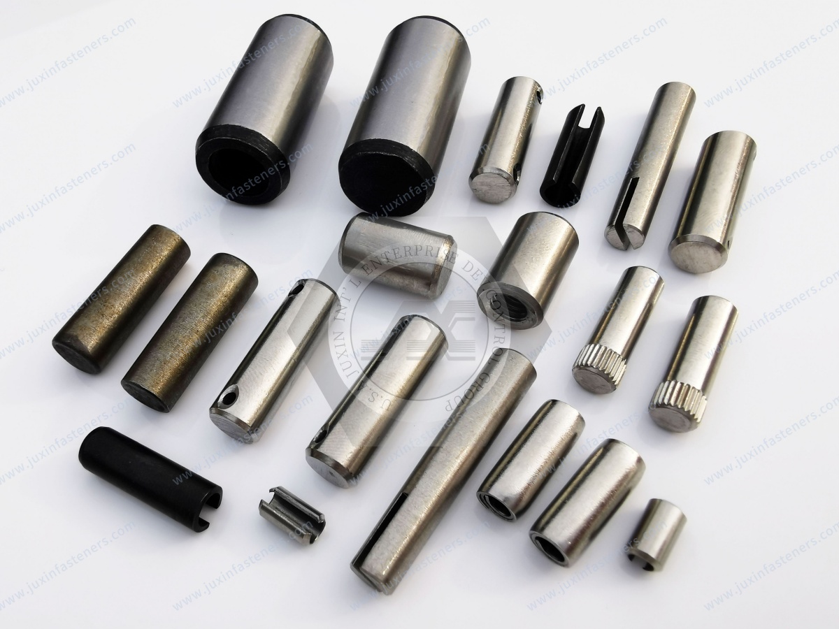
JUXIN FASTENERS supplies ISO-standard cylindrical pins, hardened dowel pins, stainless steel dowel pins, pull-out dowel pins,
oversized repair pins and custom precision locating pins for global OEM and industrial manufacturing projects.
For related engineering information, explore our guides to Precision Dowel Pins, ISO 8734 Cylindrical Pins, Spring Pins vs Dowel Pins, and other precision pin solutions.
Send us your 2D drawing, 3D model, sample or technical requirements for engineering review and quotation.
JUXIN FASTENERS
FASTENING SOLUTIONS FOR GLOBAL OEMS
Website: www.juxinfasteners.com
Email: info@juxinfasteners.com
 MORE NEWS

Sep. 27, 2026

Sep. 27, 2026

Sep. 27, 2026
Contact Us
Tel.:
+86 020 8621 0320
+86 020 3121 6067
E-mail:
Technical Support:
Navigation
SEND INQUIREY