
Call Us
+86 136 6007 9809
Call Us
+86 136 6007 9809

Sep. 23, 2023
Inch external retaining rings, also known as external snap rings, shaft retaining rings or external circlips, provide compact axial retention for components mounted on inch-dimension shafts.
Typical retained components include:
rolling bearings;
gears;
pulleys;
sprockets;
sleeves;
spacers;
rollers;
mechanical subassemblies.
These retaining systems are widely used in industrial machinery, power-transmission equipment, automotive assemblies, electric motors, pumps, compressors, gearboxes, conveyors and automated equipment.
However, specifying an inch retaining ring requires more than selecting a nominal shaft diameter.
Engineers must first identify the actual retaining-ring architecture.
The correct selection model is:
Ring Type → Shaft → Groove → Retained Component → Axial Load → Rotational Speed → Material / Finish → Installation → Validation
This distinction is particularly important because terms such as snap ring, retaining ring, circlip, wire retaining ring and external shaft ring are sometimes used loosely in commercial sourcing.
They do not always describe the same product geometry.
An external retaining ring is installed into a groove on the outside diameter of a shaft.
During installation, the ring is expanded or otherwise positioned over the shaft according to its specific design.
Once installed in the groove, the portion of the retaining ring extending beyond the groove forms a mechanical shoulder that can restrict axial movement of a mating component.
Typical applications include axial retention of:
bearings;
gears;
sleeves;
spacers;
pulleys;
rollers.
The retaining ring does not automatically perform every mechanical function in the assembly.
Its primary role is axial retention.
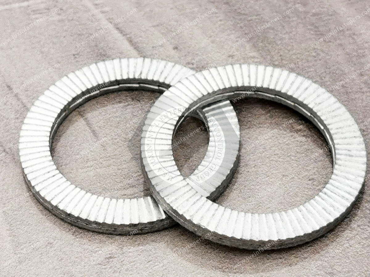
For many general-purpose tapered and reduced-cross-section inch retaining rings, ASME B18.27 is an important U.S. engineering reference.
ASME B18.27 covers multiple inch-series retaining-ring architectures rather than one single external-ring design.
These include families such as:
external retaining rings;
internal retaining rings;
E-rings;
heavy-duty external rings;
reinforced E-rings;
C-rings;
bowed retaining rings;
inverted retaining rings;
beveled retaining rings;
selected locking configurations.
This is important for procurement because:
“Inch retaining ring” is a product family—not one universal geometry.
For a conventional external shaft retaining-ring requirement within the applicable ASME B18.27 system, External Type NA1 is one relevant standardized architecture.
The ring is designed for installation on an appropriate shaft and corresponding groove.
The standard provides dimensional information associated with the ring and recommended groove geometry.
ASME B18.27 also includes Heavy Duty External Type NA4.
A heavy-duty ring should not simply be substituted for another external ring because it appears stronger.
Changing ring architecture can affect:
groove geometry;
installation requirements;
available radial space;
retained-component interface;
assembly tooling.
The ring and groove must be treated as a matched system.
Depending on the assembly, other ring types may provide different functions.
Examples include:
E-rings;
C-rings;
inverted rings;
beveled rings;
bowed rings;
locking configurations.
The appropriate architecture depends on the mechanical problem being solved.
Therefore:
Do Not Select an Inch Retaining Ring from Diameter Alone
The original version of this article described the entire product category as inch shaft flattened steel wire retaining rings.
That terminology can describe certain products, but it should not be treated as equivalent to every standardized inch retaining ring.
Retaining rings can be manufactured using different architectures and processes.
Depending on the design, they may include:
stamped tapered-section rings;
reduced-cross-section rings;
wire-formed rings;
spiral retaining rings;
other application-specific retaining products.
The drawing or governing product specification should identify which architecture is actually required.
Wire-formed and stamped retaining rings can have different:
cross-sectional geometry;
load distribution;
installation behavior;
groove requirements;
radial profile.
Therefore:
Similar Shaft Diameter ≠ Interchangeable Retaining Ring
If an OEM drawing specifies a flattened-wire ring, a conventional stamped external ring should not be substituted without engineering approval.
The reverse is also true.
Spiral retaining rings represent another retaining architecture.
They should not automatically be grouped with tapered/reduced-cross-section external rings.
Where a spiral ring is required, the applicable product standard and drawing should control the specification.
This is why purchasing teams should avoid reducing every shaft-retention inquiry to “snap ring, 1 inch.”
One of the most important sourcing distinctions is between inch-series and metric retaining rings.
A nominally similar shaft diameter does not establish interchangeability.
For example, an inch shaft and a nearby metric shaft size can appear close numerically.
But the retaining systems may differ in:
nominal diameter;
groove diameter;
groove width;
ring thickness;
radial height;
tolerances;
ring architecture.
Therefore:
Near-Equivalent Diameter ≠ Equivalent Retaining System
A procurement team should not take an inch retaining-ring size, multiply it by 25.4 and select the closest DIN retaining ring.
Likewise, a DIN 471 ring should not automatically be substituted for an ASME inch-series ring.
The groove and ring must be evaluated together.
Both can address external retaining-ring applications, but they belong to different dimensional systems.
Relevant to specified inch-series tapered and reduced-cross-section retaining rings and associated dimensional data.
Relevant to metric retaining rings for shafts and corresponding grooves.
For global OEM sourcing, the drawing should state which system controls.
When a retained component moves axially against the ring, a simplified load path is:
Retained Component → Ring → Groove Flank → Shaft
The ring therefore cannot be evaluated independently.
Complete assembly performance can depend on:
ring geometry;
ring material;
groove geometry;
shaft material;
retained-component geometry;
axial load;
rotational speed;
installation condition.
A retaining-ring catalogue may provide useful ring performance data.
But the complete shaft-retention system can fail somewhere else.
Potential limiting mechanisms include:
ring deformation;
groove-flank deformation;
shaft material yielding;
retained-component deformation;
ring displacement;
dynamic fatigue-related failure.
Therefore:
Ring Strength ≠ Complete Assembly Strength
The groove provides the interface through which the ring transfers load into the shaft.
Important groove variables can include:
groove diameter;
groove width;
groove location;
relevant edge geometry;
manufacturing tolerance.
An incorrect groove can compromise a correctly manufactured retaining ring.
A groove intended for one ring family should not automatically be used for another ring.
This is especially important when comparing:
standard external rings;
heavy-duty rings;
wire rings;
spiral rings;
metric alternatives.
The ring and groove should remain a controlled pair.
The axial position of the groove helps establish the position of the retained component.
Groove-position tolerance can therefore influence:
bearing position;
gear alignment;
pulley position;
axial clearance;
assembly stack-up.
For precision machinery, groove location can be a functional dimension rather than merely a machining detail.
The groove is machined into the shaft itself.
Therefore shaft material influences the retaining system.
Relevant variables may include:
base material;
heat treatment;
hardness;
groove-root condition;
shaft section.
A strong retaining ring installed on a relatively weak groove does not automatically create a strong assembly.
Machining a groove reduces the shaft cross-section locally.
It can also introduce a stress concentration.
If the shaft experiences:
bending;
torsion;
cyclic loading;
combined loading,
the groove should be considered in the shaft design.
Axial retention is only one part of the mechanical analysis.
The retained component pushes against the portion of the ring projecting from the shaft groove.
Its contact geometry therefore influences load transfer.
A bearing inner ring, gear, spacer or pulley can present different:
corner radii;
chamfers;
contact faces.
The retaining-ring architecture should be compatible with the retained component.
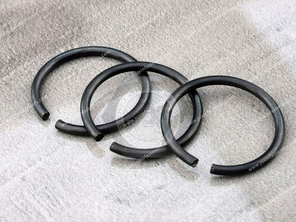
Some retaining-ring architectures place features differently to provide clearance advantages.
This can be useful when a conventional lug arrangement interferes with:
a bearing;
surrounding components;
assembly envelope.
Geometry selection should therefore consider the complete 3D assembly.
Beveled retaining-ring architectures can serve specific axial-positioning functions by interacting with corresponding assembly geometry.
They should not be substituted for conventional external rings solely because the nominal shaft size is the same.
Bowed retaining rings can be used in applications requiring specific axial take-up behavior.
Again:
Bowed Ring ≠ Standard Flat External Ring
The function and groove system should match the intended design.
E-rings are another common external retaining architecture.
Unlike conventional axially assembled external rings, E-rings can be installed radially in appropriate applications.
This can influence:
assembly access;
automation;
tooling;
component packaging.
Do not assume that an E-ring and an axial external ring are direct substitutes.
Different retaining-ring architectures use different installation motions.
A conventional external axial ring may be expanded and moved axially over the shaft.
An E-ring may be installed radially.
A wire or spiral ring can require another installation procedure.
The production process should therefore be considered during product selection.
Spring behavior allows the ring to deform during installation and recover sufficiently for proper retention.
However, elasticity should not be confused with vibration damping.
An external retaining ring is not inherently:
a vibration isolator;
a shock absorber;
a flexible coupling.
Its primary function remains mechanical retention.
The original article stated that flattened-wire retaining rings provide better elasticity and flexibility than traditional stamped rings.
That is too broad.
Mechanical behavior depends on:
material;
cross section;
geometry;
heat treatment;
installation deformation.
A wire ring may offer useful characteristics for a particular design, but it is not universally more elastic or superior.
Reducing component mass can be useful.
But retaining-ring selection should prioritize:
correct geometry;
groove compatibility;
axial capacity;
speed suitability;
environment;
installation.
A lighter ring is not automatically the better engineering choice.
External retaining rings often rotate with the shaft assembly.
As rotational speed increases, centrifugal effects become increasingly important.
The significance depends on:
ring mass;
ring geometry;
shaft diameter;
rotational speed;
groove engagement.
Therefore:
Static Axial Capacity ≠ Automatic High-Speed Capability
A statement such as:
“This retaining ring is suitable for high-speed shafts.”
is incomplete without application data.
The appropriate speed capability depends on the specific ring and assembly.
For demanding high-speed applications, evaluate:
ring design;
groove;
shaft speed;
operating temperature;
dynamic loading;
qualification requirements.
A static axial force and a cyclic axial force are not equivalent.
Dynamic operation can introduce:
repeated groove loading;
impact;
vibration;
fretting;
fatigue-related mechanisms.
The application duty cycle should therefore be included in validation where relevant.
Equipment exposed to sudden:
starts;
stops;
reversals;
impacts
can generate transient axial loads different from normal steady operation.
These should not be ignored when specifying the retaining system.
If an external retaining ring positions a gear or pulley on a shaft, that does not mean the ring should transmit the drive torque.
Torque transfer may depend on:
keyways;
splines;
interference fits;
other drive features.
Therefore:
Axial Positioning ≠ Torque Transfer
Bearings are a common application for inch external retaining rings.
Potential equipment includes:
motors;
pumps;
gearboxes;
conveyors;
industrial drives;
machine tools.
The retaining ring may provide an axial stop for the bearing inner ring in an appropriate design.
An external ring can establish a stop.
It does not automatically establish a controlled bearing preload.
Bearing preload and fixed/floating arrangements should be designed as part of the complete bearing system.
The original article listed 304 stainless steel, 316L stainless steel and a regional spring-steel designation as though these were universal standard materials.
For international OEM sourcing, this should be replaced with specification-controlled material selection.
Possible material categories can include:
carbon spring steel;
corrosion-resistant stainless spring materials;
special alloys where specifically required.
The exact material should follow:
governing standard;
customer drawing;
mechanical requirement;
corrosion environment.
Carbon spring steel is widely used for industrial retaining rings because properly controlled material and processing can provide the elastic behavior required during installation.
Performance depends on more than the material name.
Relevant variables include:
material condition;
cross section;
forming;
heat treatment where applicable;
final geometry.
Stainless materials can be considered where the environment requires increased corrosion resistance.
Potential applications can include:
humid environments;
washdown equipment;
outdoor equipment;
laboratory machinery;
food-processing equipment.
However:
Stainless Steel ≠ Corrosion-Proof
The actual environment should control grade selection.
Certain industries may use special retaining-ring materials for specific:
temperature;
corrosion;
magnetic;
strength;
aerospace
requirements.
These should be treated as drawing- or specification-controlled products.
The original article broadly described these rings as aerospace components.
That claim requires tighter engineering boundaries.
Aerospace retaining rings may be controlled by dedicated:
SAE Aerospace Standards;
customer drawings;
material specifications;
process requirements;
qualification requirements.
A generic industrial inch retaining ring should not automatically be represented as aerospace-qualified.
JUXIN FASTENERS can evaluate drawing-based requirements where manufacturing capability and project requirements are appropriate,
but aerospace flight-critical qualification should never be assumed from product geometry alone.
Industrial retaining rings may be applicable to suitable:
aerospace tooling;
maintenance equipment;
ground-support equipment;
non-flight-critical mechanical assemblies
when the governing drawing and procurement specification permit their use.
This is different from claiming qualification for aircraft flight hardware.
Surface treatment should be selected according to:
base material;
corrosion environment;
dimensional requirements;
customer specification.
Potential finish systems vary by product and project.
Where susceptible high-strength spring steel is exposed to processes that can introduce hydrogen, hydrogen-embrittlement risk requires appropriate process control.
The risk depends on:
material;
hardness;
manufacturing process;
surface-treatment process;
applied stress.
There is no universal post-treatment recipe that guarantees elimination of risk for every retaining ring.
Corrosion requirements should be based on the actual operating environment.
Laboratory corrosion tests can support coating qualification, but test hours should not be directly translated into field-service years.
The old article described flattened-wire rings as inherently wear resistant under continuous rotation.
That is too broad.
A correctly installed retaining ring is normally intended to remain properly seated relative to its groove.
Unexpected relative motion or fretting should be investigated rather than assumed to be a normal wear condition.
The ring's purpose is axial retention.
It should not automatically be designed as the sliding or rotating bearing interface for the retained component.
Where relative rotation occurs at the contact interface, the complete tribological condition should be evaluated.
Installation method depends on ring architecture.
For a conventional external axial retaining ring, a typical procedure includes the following.
Confirm:
correct ring type;
correct nominal size;
correct material/finish;
correct shaft application.
Check for:
correct dimensions;
burrs;
contamination;
machining damage.
Use appropriate retaining-ring pliers or dedicated installation tooling for the selected ring architecture.
For an external ring requiring expansion, open the ring only enough to pass over the shaft.
Avoid unnecessary over-expansion.
Move the ring into the intended groove without excessive twisting or distortion.
Allow the ring to recover into the groove.
Confirm that the ring is properly engaged before the assembly enters service.
The previous article described an installation method in which the shaft and retaining ring were inserted together into an assembly hole.
That is not a universal procedure for external shaft retaining rings.
Installation depends on the ring architecture and the surrounding assembly.
For conventional external axial rings, the ring is normally installed into the shaft groove using the appropriate installation method.
The previous article also stated that the opening should face outward.
That is not a universal engineering rule for every external retaining-ring system.
Orientation requirements should come from:
product design;
assembly drawing;
installation procedure.
Do not create an orientation rule where the governing specification does not require one.
An external ring can be permanently deformed if opened too far.
Potential consequences include:
increased free diameter;
reduced groove engagement;
poor seating;
reduced retention reliability.
Use controlled tooling.
Do not hammer a retaining ring into place unless a specific ring architecture and approved installation method explicitly permits the required tool/process.
Improvised installation can damage:
ring geometry;
groove;
shaft;
surrounding components.
High-volume production may use automated ring installation.
Automation should control:
ring feeding;
orientation;
deformation;
positioning;
seating.
Not every retaining-ring architecture is equally suitable for automated feeding.
Automation compatibility should be specifically validated.
Removal does not automatically mean a ring is suitable for reuse.
Service can affect:
free diameter;
ring geometry;
surface condition;
elastic recovery.
For critical assemblies, follow the equipment manufacturer's service procedure.
One advantage of many retaining-ring systems is serviceability.
But:
Removable Component ≠ Unlimited-Life Component
If repeated service is expected, define the maintenance strategy during design.
Possible causes include:
incorrect ring;
incorrect groove;
axial overload;
excessive installation deformation;
high rotational effects;
groove damage;
unsuitable shaft material;
dynamic loading.
Do not automatically conclude that the ring material was too weak.
The shaft groove may fail before the ring.
Possible contributors include:
relatively soft shaft material;
high axial load;
insufficient groove support;
repeated dynamic loading.
The ring and shaft must therefore be analyzed together.
Potential causes include:
over-expansion;
overload;
excessive centrifugal effects;
incorrect tooling.
Replacing the ring without correcting the installation process can reproduce the failure.
Potential contributors can include:
material/process defect;
excessive installation deformation;
unsuitable surface-treatment process;
severe cyclic loading.
Root-cause analysis should evaluate the complete history of the component.
This failure is especially important in international supply chains.
A sourcing team may replace an inch ring with a visually similar metric part.
The part may appear to install, but groove engagement can be incorrect.
Therefore:
Never Approve Inch/Metric Substitution from Nominal Diameter Alone
Inch external retaining rings may be used in suitable:
pumps;
compressors;
gearboxes;
conveyors;
packaging machinery;
material-handling systems;
industrial drives.
Application-specific load and speed requirements should control selection.
Potential uses can include appropriate:
transmission subassemblies;
motor assemblies;
pumps;
drivetrain auxiliary components.
Automotive safety-critical applications require customer-specific validation.
A generic retaining ring should not automatically be represented as qualified for:
braking;
steering;
suspension;
occupant-restraint
systems.
Inch retaining rings can provide compact axial retention in suitable motor shaft and bearing assemblies.
Selection should consider:
rotational speed;
bearing arrangement;
temperature;
service duty.
Potential applications include:
bearing retention;
drive assemblies;
auxiliary rotating components.
Pressure containment and shaft sealing remain separate engineering functions.
Inch retaining rings may be used in:
drive mechanisms;
feed systems;
bearing assemblies;
auxiliary spindle components.
High-speed spindle applications require dedicated rotational-system evaluation.
Compact ring geometry can be useful in:
actuators;
gearboxes;
rollers;
automation mechanisms.
Rapid acceleration and reversal may introduce dynamic conditions that require specific validation.
Retaining rings can support compact axial positioning where:
groove position;
component tolerances;
axial stack-up
are carefully controlled.
The ring alone does not determine positioning accuracy.
A retaining ring is physically small, but a failure can allow a much larger component to move axially.
Possible consequences can include:
bearing displacement;
gear misalignment;
abnormal noise;
shaft damage;
assembly downtime.
However, “high quality” should not simply mean a harder or heavier ring.
Quality means:
Correct Standard + Correct Geometry + Correct Material + Correct Groove + Controlled Manufacturing + Correct Installation
A standard ASME ring can be sourced by its controlled designation where the standard fully describes the required product.
A project may instead require a drawing-controlled part because of:
special material;
modified geometry;
special finish;
special testing;
unusual packaging;
legacy cross-reference.
The RFQ should make this distinction clear.
OEMs often need to replace an existing supplier's retaining ring.
A cross-reference can be useful as a starting point.
But:
Cross-Reference Candidate ≠ Automatic Drop-In Equivalent
A second-source review should compare:
governing standard;
ring type;
nominal size;
critical dimensions;
groove;
material;
finish;
application requirements.
Two parts described commercially as:
“1-inch external snap ring”
may not be functionally identical.
They can belong to different ring families.
Supplier qualification should therefore use a controlled drawing, standard designation or approved sample/specification rather than a generic description.
Engineers may search:
inch retaining ring standard;
ASME B18.27 retaining ring;
external snap ring groove dimensions;
inch shaft retaining ring load capacity;
external circlip high speed;
wire retaining ring vs stamped retaining ring;
DIN 471 vs inch retaining ring.
They need engineering boundaries and selection data.
Procurement teams may search:
inch retaining ring supplier;
external snap ring manufacturer;
ASME B18.27 supplier;
inch circlip supplier;
shaft retaining ring OEM;
custom wire retaining ring supplier;
retaining ring second source.
They need an identifiable product, controlled specification and scalable supply path.
Determine whether the requirement is controlled by:
ASME B18.27;
another standard;
OEM drawing;
legacy supplier specification.
Determine whether it is:
external axial ring;
heavy-duty external ring;
E-ring;
C-ring;
inverted ring;
bowed ring;
beveled ring;
wire-formed ring;
another design.
Specify:
nominal inch diameter;
material;
heat treatment;
surrounding geometry.
Control the groove dimensions required by the selected ring.
Define whether the ring retains a:
bearing;
gear;
pulley;
sleeve;
spacer;
other component.
Specify:
magnitude;
direction;
static/dynamic condition;
shock.
Evaluate centrifugal effects where applicable.
Consider:
temperature;
corrosion;
moisture;
chemicals;
lubrication.
Use the governing specification and environment.
Determine:
manual tooling;
dedicated applicator;
automated assembly.
Evaluate:
Ring + Groove + Shaft + Retained Component + Load + Speed + Installation
Create a controlled production specification before supplier approval.
When requesting an engineering review or quotation from JUXIN FASTENERS, provide where applicable:
governing standard;
ASME B18.27 type if applicable;
existing part number;
existing supplier reference;
customer drawing;
ring architecture;
nominal shaft diameter;
shaft drawing;
groove diameter;
groove width;
groove location;
groove tolerances;
shaft material;
shaft heat treatment;
retained component;
retained-component drawing;
axial load;
load direction;
static/dynamic condition;
shock requirement;
rotational speed;
operating temperature;
corrosion environment;
lubricant or chemical exposure;
ring material requirement;
surface-finish requirement;
installation method;
automated/manual assembly;
reuse/service requirement;
inspection requirement;
documentation requirement;
sample quantity;
pilot quantity;
production quantity;
projected annual demand;
packaging requirement.
ASME B18.27 is an important U.S. standard for specified tapered and reduced-cross-section retaining rings in the inch series, covering multiple external, internal and other retaining-ring types.
No. It covers multiple retaining-ring families including external, internal, E-ring and other configurations.
No. Other ring architectures and drawing-controlled products exist. The actual governing specification should be identified.
Not necessarily. Wire-formed and stamped/tapered retaining rings can have different geometry, groove requirements and mechanical behavior.
Not automatically. DIN 471 is a metric shaft-retaining-ring system. The ring and groove dimensions must be compared rather than converting nominal diameter alone.
The complete system matters, including ring geometry, groove geometry, shaft material, retained-component interface, axial load, speed and dynamic conditions.
Potentially, but suitability depends on the specific ring and assembly. Rotational speed and centrifugal effects should be evaluated.
Its primary role is axial retention. Gear or pulley torque normally requires a separate torque-transfer mechanism.
No. Material selection depends on spring performance, environment, geometry, processing and cost.
Aerospace applications may require dedicated SAE/AS, customer or program specifications and qualification. A generic industrial inch retaining ring should not automatically be considered aerospace-qualified.
Reuse should not be assumed. Removal can affect geometry and elastic recovery.
A legacy part number can help identify a candidate, but engineering should confirm the governing standard, dimensions, groove, material, finish and application before approving a second source.
JUXIN FASTENERS supports OEM and industrial sourcing for retaining and spring-fastener components including:
inch external retaining rings;
external snap rings;
shaft retaining rings;
application-specific wire retaining rings;
DIN 471 external retaining rings;
DIN 472 internal retaining rings;
spring washers;
spring fasteners;
blind rivet nuts;
self-clinching fasteners;
weld fasteners;
threaded inserts;
drawing-based fasteners;
CNC-machined components.
For a standard inch retaining-ring requirement, provide the governing standard or existing drawing, ring type, nominal size, material/finish requirement and production quantity.
For a legacy-part replacement or second-source project, send the existing sample, supplier part number, drawing and shaft/groove information where available.
For an engineering-driven application, also provide axial load, rotational speed, shaft material, retained component, environment and installation method.
For an OEM quotation, sample request, second-source evaluation or production sourcing project, contact:
Do not begin an inch retaining-ring project with only:
“I need a 1-inch snap ring.”
Begin with:
“Which retaining-ring architecture, groove and load system does this assembly require?”
The reliable sourcing path is:
Standard / Drawing → Ring Architecture → Inch Shaft → Groove → Retained Component → Axial Load → Speed → Material / Finish → Installation → Validation → Controlled Specification → RFQ
That approach prevents false inch/metric substitutions, incorrect groove matching and unreliable supplier cross-references while creating a specification that both engineering and procurement teams can use.
 MORE NEWS

Sep. 27, 2026

Sep. 27, 2026

Sep. 27, 2026
Contact Us
Tel.:
+86 020 8621 0320
+86 020 3121 6067
E-mail:
Technical Support:
Navigation
SEND INQUIREY