
Call Us
+86 136 6007 9809
Call Us
+86 136 6007 9809

Sep. 23, 2023
DIN 471 external retaining rings, also known as shaft circlips, external circlips, external snap rings or retaining rings for shafts, provide compact axial retention for components mounted on shafts.
Installed into a machined groove on the outside diameter of a shaft, the retaining ring forms a mechanical shoulder that can help prevent axial displacement of components such as:
rolling bearings;
gears;
pulleys;
sprockets;
sleeves;
spacers;
rollers;
mechanical subassemblies.
DIN 471 retaining rings are widely used in industrial machinery, power-transmission equipment, automotive assemblies, gearboxes,
pumps, compressors, conveyors, machine tools, robotics and automated equipment.
However, reliable shaft retention requires much more than selecting a circlip according to nominal shaft diameter.
The correct engineering model is:
Retaining Ring + Shaft Groove + Shaft Material + Retained Component + Axial Load + Rotational Speed + Installation Process
The retaining ring is only one part of the complete load-transfer system.
DIN 471 specifies retaining rings for shafts and their corresponding grooves.
The current DIN 471:2026-05 standard covers normal and heavy types.
The primary function of a DIN 471 retaining ring is to locate or retain suitable components axially on a shaft.
A typical example is a rolling bearing mounted on a shaft.
After the bearing reaches its designed axial position, an external retaining ring installed in the shaft groove can create a compact mechanical stop against axial movement.
This can eliminate the need for a threaded shaft end, retaining nut or separate bolted retaining plate in suitable applications.
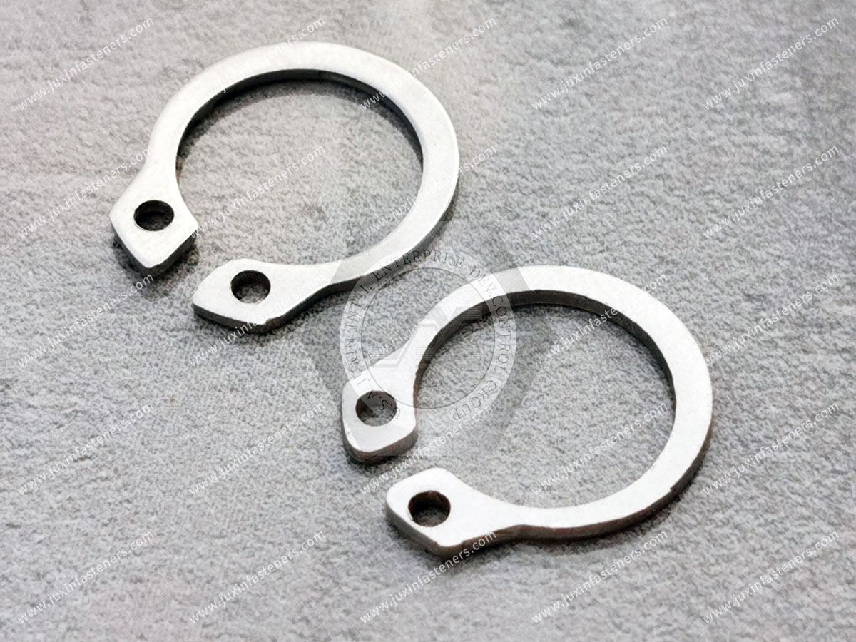
DIN 471 and DIN 472 are closely related retaining-ring standards, but they apply to opposite mounting geometries.
DIN 471 rings are installed into grooves on the outside of shafts.
The ring is expanded during installation so it can pass over the shaft and then contract into the groove.
DIN 472 rings are installed inside grooves in bores or housings.
They are compressed during installation and then expand outward into the internal groove.
A useful engineering and procurement distinction is:
DIN 471 = Shaft = External Retaining Ring
DIN 472 = Bore = Internal Retaining Ring
The two products are not interchangeable.
The retaining mechanism is sometimes described simply as the ring “holding the bearing on the shaft.”
For engineering purposes, the load path is more important.
When a retained component moves axially against the ring, load can be transferred through:
Retained Component → Retaining Ring → Shaft Groove Flank → Shaft
This means axial retention depends on the complete mechanical system.
Important variables include:
ring geometry;
ring material condition;
shaft diameter;
groove diameter;
groove width;
groove location;
shaft material;
shaft heat-treatment condition;
retained-component contact geometry;
axial load;
dynamic loading;
installation condition.
Therefore:
Retaining Ring Strength ≠ Complete Shaft-Retention Capacity
A correctly manufactured DIN 471 retaining ring installed in an unsuitable groove can still produce an unreliable assembly.
The groove is the structural interface that transfers ring load into the shaft.
An unsuitable groove may contribute to:
incomplete ring seating;
excessive ring movement;
groove-edge deformation;
local shaft damage;
reduced axial capacity;
ring displacement.
DIN 471 should therefore be treated as a ring-and-groove system, not simply as a catalogue ring size.
A sourcing inquiry may begin with:
“DIN 471 for a 30 mm shaft.”
That identifies an important dimensional requirement.
But engineering selection may also require:
normal or heavy type;
groove geometry;
shaft material;
shaft hardness;
retained component;
axial load;
rotational speed;
operating environment;
surface requirement;
installation method.
For OEM sourcing, the complete application matters.
DIN 471 covers normal and heavy types.
The correct type should be selected according to the applicable standard dimensions and the actual mechanical requirements.
A heavy-type ring should not simply be treated as a universally superior replacement.
Changing the ring section or geometry can affect:
groove requirements;
installation force;
radial envelope;
surrounding component clearance;
assembly tooling.
The ring and groove must remain a matched system.
A typical external retaining ring includes:
curved spring body;
open ends;
installation lugs;
plier holes.
During installation, external circlip pliers engage the holes and expand the ring.
The ring is opened only enough to pass over the shaft and reach the groove.
When the pliers are released, the ring contracts into the groove.
The spring characteristics of the ring allow controlled deformation during installation.
The material must tolerate expansion and recover sufficiently for groove engagement.
This elasticity does not mean the retaining ring is automatically:
a vibration damper;
a shock absorber;
a flexible coupling;
a shaft-alignment device.
Its primary role is axial retention.
One of the most important practical installation rules is to avoid unnecessary expansion.
If the ring is expanded substantially beyond what is required to pass over the shaft, permanent deformation may occur.
Potential consequences include:
increased free diameter;
reduced groove engagement;
distorted ring geometry;
uneven contact;
compromised retention.
Therefore:
More Expansion ≠ Easier or Better Installation
After installation, the ring should be correctly engaged with the intended shaft groove.
Incomplete seating may result from:
incorrect ring size;
incorrect groove dimensions;
burrs;
contamination;
installation damage;
excessive ring expansion;
unsuitable pliers.
A ring that appears to be “on the shaft” is not necessarily correctly installed.
External circlips are primarily used to control axial movement.
They should not automatically be treated as structural solutions for every force acting on a rotating assembly.
The complete system may also experience:
radial bearing forces;
bending;
torsion;
vibration;
shock;
centrifugal effects.
These require separate engineering consideration.
The original article correctly identified an important concept: the retaining ring and the shaft groove can have different load capacities.
This concept should be retained, but with a more complete engineering interpretation.
Potential limiting mechanisms include:
The ring may deform or lose its intended geometry under excessive axial load.
The groove flank or surrounding shaft material may deform before the ring reaches its own limiting capacity.
The retained component may locally deform or interact unfavorably with the ring.
Repeated load, shock, speed or vibration can create failure mechanisms not represented by a simple static capacity number.
The usable assembly load therefore depends on the weakest relevant part of the complete system together with the required design margin.
Instead of thinking only:
Ring Capacity vs Groove Capacity
engineers should evaluate:
Retained Component → Ring Contact → Ring Body → Groove Flank → Shaft Core
Each interface can influence the final design.
A DIN 471 ring can be used with many shaft materials where the complete assembly is appropriate.
But shaft material can strongly influence groove behavior.
Potential shaft materials include:
carbon steel;
alloy steel;
stainless steel;
hardened steel;
other engineering materials.
The same ring does not necessarily produce the same axial capacity on every shaft.
If the shaft groove is relatively soft, the groove flank may deform under axial loading.
If the shaft is highly hardened, other manufacturing and stress-concentration considerations may become important.
The shaft material and heat-treatment condition should therefore be considered as part of the retention design.
Machining a groove into a shaft changes the shaft cross-section.
The groove can also create a local stress concentration.
This matters particularly where the shaft experiences:
bending;
torsion;
cyclic loading;
fatigue-sensitive duty.
A retaining-ring groove should not be evaluated only for axial retaining capacity while ignoring the effect of the groove on the shaft itself.
Groove diameter influences:
ring seating;
radial engagement;
load transfer;
assembly geometry.
Using an outdated or incorrectly copied groove dimension can affect the retention system even when the ring itself is correct.
For current projects, groove dimensions and tolerances should follow the applicable DIN 471:2026-05 requirements and customer drawing.
The current DIN 471:2026-05 edition replaces DIN 471:2011-04.
The revision updates normative references and corrosion-protection designation examples, includes editorial revisions and corrects specified groove-diameter tolerance information for part of the dimensional range.
For new OEM designs and controlled drawings, engineering teams should therefore verify requirements against the current edition rather than relying on old catalogue data copied from previous DIN 471 editions.
Groove width must also match the applicable retaining-ring geometry.
An unsuitable groove width can contribute to:
excessive axial play;
poor ring support;
incomplete seating;
undesirable load distribution.
The axial location of the groove helps establish the position of the retained component.
Groove-position tolerance may therefore affect:
bearing location;
gear position;
pulley position;
spacer stack-up;
axial end play.
In precision assemblies, groove location can be as important as the ring dimensions.
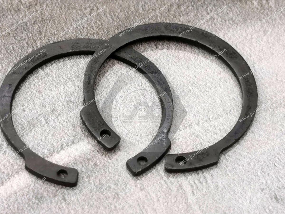
The face of the bearing, gear, pulley, sleeve or spacer that contacts the ring influences load transfer.
The contact interface should provide an appropriate load path.
A correctly selected DIN 471 ring cannot compensate for unsuitable retained-component geometry.
A retaining ring may be used to limit axial movement without necessarily creating a completely rigid axial stack.
Engineers should distinguish between:
preventing component escape;
establishing axial position;
controlling end play;
creating preload.
These are different functions.
A retaining ring can provide an axial stop.
It does not automatically create or control bearing preload.
Where a bearing arrangement requires preload, the complete bearing system must be designed accordingly.
A ring that supports a particular static load condition should not automatically be assumed to provide the same reliability under repeated dynamic loading.
Dynamic applications can introduce:
cyclic groove loading;
repeated ring contact;
impact;
fretting;
fatigue-related mechanisms.
The operating duty cycle should therefore be included in validation for demanding applications.
A short-duration axial impact can create a different mechanical condition from a steady static load.
Applications exposed to:
impacts;
emergency stops;
reciprocating motion;
abrupt direction changes
may require additional evaluation.
External retaining rings are mounted on rotating shafts in many applications.
As rotational speed increases, centrifugal effects become increasingly relevant.
The ring should therefore not be selected from axial load alone where rotational speed is significant.
An external ring rotating with a shaft experiences outward inertial effects.
At higher rotational speed, this can influence radial seating behavior.
The significance depends on factors such as:
ring geometry;
ring mass;
shaft diameter;
rotational speed;
groove engagement.
Therefore:
Adequate Static Axial Capacity ≠ Automatic High-Speed Suitability
There is no responsible universal statement such as:
“DIN 471 rings are safe up to X rpm.”
The appropriate speed limit depends on the specific ring and system.
For high-speed applications, use supplier/standard data and application-specific engineering validation.
In many shaft assemblies, the ring is installed on the rotating shaft and therefore participates in the rotating assembly.
However, the old statement that the ring “must rotate together with the shaft” should not be used as a universal installation acceptance criterion.
The critical requirements are:
correct groove engagement;
intended axial retention;
acceptable behavior under the specified operating speed and load.
Relative movement, fretting or abnormal ring behavior should be assessed according to the actual application.
A standard DIN 471 ring should not automatically be specified for every high-speed rotating system.
Applications such as specialized:
turbines;
high-speed rotors;
generator retaining systems;
aerospace rotating assemblies
may use dedicated retention technologies, materials and qualification requirements.
Do not assume that the phrase “retaining ring” means DIN 471 is appropriate.
Spring steel is widely used because DIN 471 rings must elastically expand during installation and recover sufficiently to engage the shaft groove.
The complete material condition and manufacturing process influence:
strength;
elasticity;
dimensional stability;
installation behavior.
Material should follow the applicable DIN requirement or customer specification.
Where corrosion resistance is required, suitable corrosion-resistant materials may be considered depending on:
environment;
ring size;
mechanical requirement;
customer specification.
Applications may include equipment exposed to:
humidity;
washdown;
outdoor conditions;
chemicals;
marine atmospheres.
However:
Stainless Steel ≠ Corrosion-Proof
Material selection should be environment-specific.
Surface requirements should be selected according to:
base material;
corrosion exposure;
installation deformation;
customer specification.
Do not specify a coating only from appearance.
Dark conversion finishes with oil protection are commonly encountered on industrial spring components.
They may provide useful storage and handling protection for suitable environments.
They should not automatically be described as high-corrosion-resistance systems.
Where susceptible high-strength spring-steel components are electroplated, hydrogen-embrittlement risk must be considered.
Risk depends on factors including:
material;
hardness;
processing;
hydrogen exposure;
applied stress.
There is no universal baking cycle that guarantees elimination of risk for every retaining ring.
Where salt-spray testing is specified, the result represents performance under a controlled laboratory method.
Salt-spray hours should not be directly translated into field-service years.
Actual corrosion performance depends on the real environment.
Hardness can be part of retaining-ring material and process control.
Where Vickers hardness testing is required, ISO 6507-1:2023 defines the Vickers hardness test method for metallic materials within its scope.
The acceptance requirement itself should come from the applicable DIN 471 edition or customer specification.
Depending on the product and control plan, inspection may include relevant:
ring dimensions;
thickness;
lug geometry;
plier-hole geometry;
functional dimensions.
Inspection should be based on the controlled product specification rather than generic internet tables.
Dimensional compliance ultimately needs to support correct installation and groove engagement.
For production qualification, functional checks may therefore be appropriate when specified.
Correct installation is essential.
Confirm:
correct shaft diameter;
correct DIN 471 ring;
groove condition;
groove dimensions;
retained-component position.
Insert the plier tips into the ring holes.
Use tooling appropriate to the ring size.
Open the ring sufficiently to pass over the shaft.
Avoid unnecessary over-expansion.
Guide the ring to the groove without twisting or damaging it.
Allow the ring to contract into the groove in a controlled manner.
Verify that the ring is properly engaged in the groove before the assembly enters service.
Because an external circlip must open to pass over the shaft, technicians may be tempted to expand it excessively.
This can permanently increase the ring's free diameter.
Potential consequences include:
reduced radial engagement;
poor seating;
increased risk of displacement.
Use the minimum practical expansion required for assembly.
Where possible, assembly planning should minimize unnecessary travel of an expanded ring along the shaft.
The installation process should avoid:
scratching critical surfaces;
excessive ring deformation;
interference with other shaft features.
Improvised tools can damage:
lug holes;
ring ends;
ring geometry.
Suitable circlip pliers improve installation control and operator safety.
High-volume production may use dedicated retaining-ring installation equipment.
Automation should control:
expansion;
positioning;
release;
seating.
Production-intent validation is particularly important where installation speed is high.
A ring may sometimes appear undamaged after removal.
That does not automatically mean it should be reused.
Removal can affect:
free diameter;
ring geometry;
lug condition;
surface finish;
elastic recovery.
For critical equipment, the reuse policy should follow the equipment manufacturer's maintenance specification or validated service procedure.
Retaining rings are attractive partly because they can be removed relatively easily.
But:
Easy Removal ≠ Unlimited Reuse
For some maintenance programs, installing a new retaining ring after disassembly may be the appropriate controlled practice.
Possible causes include:
incorrect ring;
incorrect groove;
burrs;
contamination;
excessive expansion;
installation error.
Possible contributors include:
excessive axial load;
unsuitable groove geometry;
groove damage;
incorrect ring size;
permanent ring deformation;
excessive rotational effects.
Possible causes include:
insufficient shaft material strength;
high axial loading;
unsuitable groove geometry;
dynamic loading.
Potential causes include:
installation over-expansion;
excessive centrifugal effects;
overload;
material/process problems.
Potential contributors can include:
material or manufacturing defects;
excessive installation deformation;
unsuitable processing;
cyclic service conditions.
Failure analysis should investigate the entire ring-groove-shaft system.
If an external circlip comes out of the groove, simply ordering a “stronger” ring may not solve the problem.
The root cause may instead be:
groove dimensions;
shaft material;
over-expansion during installation;
excessive speed;
axial overload;
dynamic impact;
incorrect component contact.
Therefore:
Retaining Ring Failure Analysis Must Include the Shaft Groove and Operating System
One of the most common uses of DIN 471 external retaining rings is axial location of bearings on shafts.
Potential equipment includes:
gearboxes;
electric motors;
pumps;
conveyors;
machine tools;
industrial drives.
The ring can form an axial stop against the bearing inner ring in appropriate designs.
The complete bearing arrangement must still account for thermal expansion, fixed/floating bearing strategy and bearing-manufacturer recommendations.
DIN 471 rings can be used to axially locate suitable gears on shafts.
However, the ring does not transmit the shaft's primary torque merely because it positions the gear.
Torque transfer may instead depend on features such as:
splines;
keys;
interference fits;
other drive interfaces.
Therefore:
Axial Retention ≠ Torque Transmission
External retaining rings can also help position suitable pulleys or sprockets.
Again, the torque-transfer mechanism should be analyzed separately.
The ring should not automatically be treated as the component responsible for transmitting drive torque.
Potential applications include:
pumps;
compressors;
packaging machinery;
conveyors;
industrial gearboxes;
production machinery.
Retaining rings provide compact axial location where the shaft and groove are appropriately designed.
DIN 471 retaining rings may be used in appropriate:
transmission assemblies;
drivetrain components;
electric motor assemblies;
pumps;
auxiliary mechanical systems.
A standard DIN 471 ring should not automatically be represented as qualified for every:
steering;
braking;
suspension;
wheel-end;
occupant-safety
application.
Safety-critical applications require customer-specific engineering and validation.
Machine tools may use external retaining rings in:
spindle-related auxiliary assemblies;
feed mechanisms;
gear systems;
bearing arrangements.
High-speed spindle applications require particular attention to rotational effects and the complete spindle design.
DIN 471 rings may be suitable for compact:
actuator assemblies;
gearboxes;
roller systems;
bearing assemblies;
automation mechanisms.
Applications with rapid acceleration, reversal or repeated shock require appropriate dynamic validation.
External retaining rings can be used in suitable motor shaft assemblies for axial positioning.
Motor speed, thermal behavior and bearing arrangement must be considered.
The ring is only one component in the rotor/shaft system.
Potential applications include suitable:
drive shafts;
bearing assemblies;
auxiliary rotating components.
Pressure containment, shaft sealing and other functional requirements remain separate from retaining-ring performance.
A shaft collar can provide a removable axial stop without machining the same type of retaining-ring groove.
However, it may require greater:
radial space;
axial space;
mass.
DIN 471 rings provide a compact alternative where groove machining and load requirements are appropriate.
A threaded shaft nut can provide:
high axial capacity;
adjustment;
controlled bearing preload
in suitable systems.
However, it may require:
shaft threads;
locking features;
greater axial space.
A DIN 471 ring is generally a compact axial stop rather than an adjustable preload device.
A machined shoulder can provide robust axial positioning but may complicate assembly because components cannot pass through the shoulder.
A retaining-ring groove can allow components to be assembled first and retained afterward.
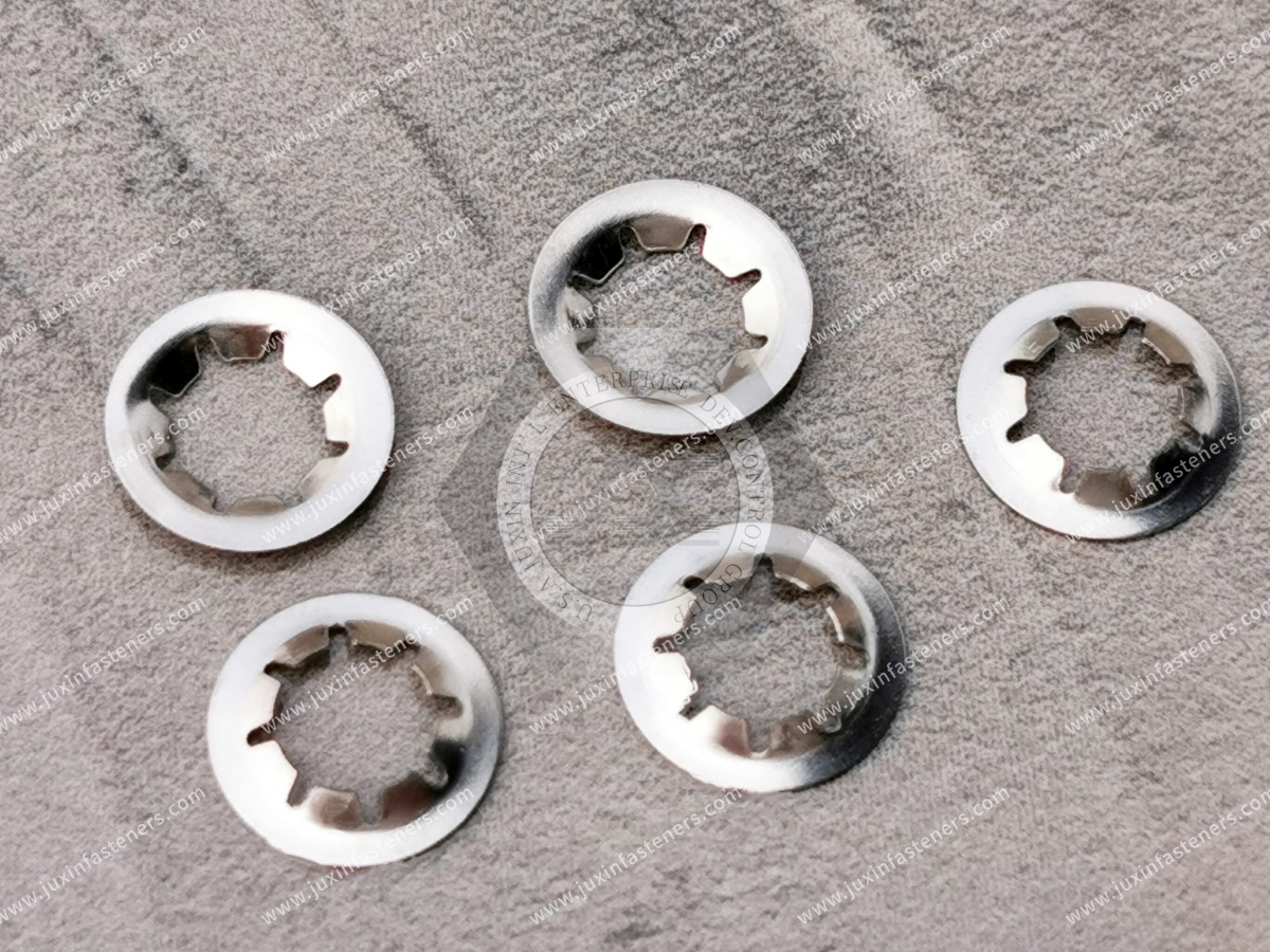
Push-on retainers use a different retention mechanism and may not require a conventional machined DIN 471 groove.
They should not be treated as direct DIN 471 equivalents.
Selection depends on:
service load;
removal requirements;
shaft geometry;
production method.
Determine whether the ring retains a:
bearing;
gear;
pulley;
sprocket;
sleeve;
spacer;
other component.
Specify:
nominal diameter;
material;
heat-treatment condition;
surrounding geometry.
Use the current DIN 471 requirements and controlled drawing.
Control:
groove diameter;
groove width;
groove position;
relevant tolerances.
Identify:
magnitude;
direction;
static or dynamic condition;
impact/shock.
For rotating shafts, evaluate whether speed and centrifugal effects are significant.
Review:
groove strength;
shaft section;
stress concentration;
bending/torsional duty where relevant.
Consider:
temperature;
moisture;
chemicals;
lubricants;
corrosion.
Specify:
manual pliers;
dedicated tooling;
automated installation.
Evaluate:
Ring + Groove + Shaft + Retained Component + Load + Speed + Installation
Engineers may search:
DIN 471 retaining ring load capacity;
external circlip groove dimensions;
shaft retaining ring design;
retaining ring axial load;
external circlip high-speed shaft;
retaining ring groove failure;
DIN 471 vs DIN 472.
Their objective is mechanical reliability.
Purchasing teams may search:
DIN 471 retaining ring supplier;
external circlip manufacturer;
shaft retaining ring supplier;
DIN 471 bulk supplier;
spring steel circlip supplier;
OEM retaining ring manufacturer.
Their objective is supplier availability, specification compliance and production consistency.
The RFQ should satisfy both search intentions.
A DIN 471 designation can define the standardized product.
But an OEM project may also impose additional requirements for:
material;
surface condition;
corrosion performance;
inspection;
documentation;
packaging;
customer drawing.
These requirements should be stated separately.
Not every DIN 471 order automatically requires:
full MTR;
PPAP;
special certificates;
custom test reports.
Procurement should define only the documentation required by the actual project.
This reduces quotation ambiguity and unnecessary supply-chain cost.
For new applications, production-intent samples can be evaluated using the actual:
shaft;
groove;
retained component;
installation tooling.
This is particularly valuable for:
high-speed systems;
softer shaft materials;
high axial loads;
automated assembly;
dynamic applications.
A second-source DIN 471 ring should meet the controlled DIN and drawing requirements.
However, OEM teams should still evaluate customer-specific characteristics such as:
material;
finish;
installation behavior;
documentation;
critical assembly performance.
A supplier change should be controlled according to the risk of the application.
Procurement should evaluate more than ring unit price.
The true sourcing cost can include:
Ring Price + Incoming Inspection + Installation Time + Assembly Defects + Rework + Downtime + Inventory + Maintenance
A slightly cheaper ring that creates installation problems can increase total production cost.
When submitting a DIN 471 inquiry to JUXIN FASTENERS, provide where applicable:
DIN 471 designation;
nominal shaft diameter;
normal or heavy type;
required quantity;
annual volume;
retained component;
application;
industry;
shaft material;
shaft heat-treatment condition;
shaft drawing;
groove diameter;
groove width;
groove location;
groove tolerances;
retained-component geometry;
axial load requirement;
load direction;
static/dynamic load condition;
shock requirement;
rotational speed;
operating temperature;
corrosion environment;
lubricant/chemical exposure;
ring material requirement;
surface-treatment requirement;
installation method;
manual or automated assembly;
customer drawing;
inspection requirement;
documentation requirement;
sample quantity;
production packaging requirement.
DIN 471 is the standard for retaining rings for shafts, covering normal and heavy types and their corresponding shaft grooves.
The current edition is DIN 471:2026-05.
DIN 471 is an external retaining ring installed on a shaft. DIN 472 is an internal retaining ring installed in a bore.
Common English search terms include external retaining ring, external circlip, shaft circlip, external snap ring and retaining ring for shaft.
The retained component transfers axial load into the ring, which transfers the load into the shaft groove and shaft.
Relevant variables include ring geometry, groove geometry, shaft material, retained-component contact, axial load, dynamic conditions and operating speed.
No. The groove or shaft may become the limiting part of the system.
Potentially, depending on the specific ring and system. Centrifugal effects become increasingly important as speed increases, so high-speed applications require appropriate evaluation.
No. Maximum appropriate speed depends on the specific ring and assembly.
Its primary function is axial retention. Torque transfer in gears, pulleys or sprockets normally requires a separately designed torque-transfer interface.
Not automatically. It can provide an axial stop, but bearing preload requires complete bearing-system design.
Reuse should not be assumed. Removal and reinstallation can change ring geometry and elastic recovery.
Possible causes include incorrect groove geometry, axial overload, over-expansion during installation, ring deformation, incorrect ring size, dynamic effects or excessive rotational conditions.
At minimum, provide the DIN 471 size/designation, quantity and any special material, finish, documentation or packaging requirements. For engineering review, also provide shaft, groove, load and speed information.
JUXIN FASTENERS supports OEM and industrial sourcing for fastening and retention components including:
DIN 471 external retaining rings;
DIN 472 internal retaining rings;
spring washers;
spring fasteners;
blind rivet nuts;
weld fasteners;
self-clinching fasteners;
threaded inserts;
drawing-based fasteners;
CNC-machined components.
For standard DIN 471 sourcing, provide the complete designation, quantity, material or finish requirements where applicable and projected annual demand.
For engineering-driven applications, provide the shaft drawing, groove geometry, retained component, axial load, rotational speed, operating environment and installation conditions.
For an OEM quotation, sample request, supplier-development project or second-source evaluation, contact:
A DIN 471 retaining ring should not be selected only because its nominal size matches the shaft.
The more reliable engineering pathway is:
Shaft → Retained Component → Axial Load → Rotational Speed → Ring Type → Groove → Shaft Material → Environment → Installation → Validation → Controlled Specification → RFQ
That approach turns a small external circlip into a properly controlled axial-retention system for industrial production.
 MORE NEWS

Sep. 27, 2026

Sep. 27, 2026

Sep. 27, 2026
Contact Us
Tel.:
+86 020 8621 0320
+86 020 3121 6067
E-mail:
Technical Support:
Navigation
SEND INQUIREY