
Call Us
+86 136 6007 9809
Call Us
+86 136 6007 9809

Jan. 13, 2024
Power distribution boxes, switchgear, transformers, control cabinets and industrial electrical equipment contain bolted joints that may experience vibration,
thermal cycling, environmental exposure and long service periods.
Where a threaded joint is required, selecting the nut is not simply a question of:
“Standard nut or lock nut?”
Engineers need to understand why the joint could lose its required mechanical condition in the first place.
Important variables include:
Bolt preload
Joint stiffness
Transverse loading
Vibration
Bearing-surface settlement
Friction
Tightening method
Surface coating
Temperature
Corrosion
Parent materials
Serviceability
A locking feature can help address particular loosening mechanisms, but it does not correct an inadequately designed bolted joint.
JUXIN FASTENERS supplies serrated flange nuts, nylon insert lock nuts, stainless steel lock nuts, carbon steel lock nuts,
flange nuts and drawing-based custom nuts for electrical equipment and industrial OEM applications.
Typical applications include:
Power distribution boxes
Switchgear systems
Electrical cabinets
Transformer equipment
Industrial control systems
Power electronics
Energy equipment
Renewable-energy equipment
Industrial machinery
Railway electrical equipment
This guide explains how engineers and procurement teams can select locking nuts according to the complete joint rather than choosing an “anti-loosening nut” from the product name alone.
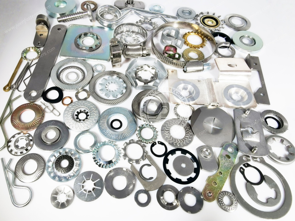
A correctly assembled bolted joint relies on controlled tension in the bolt to clamp the joined components together.
This clamping condition can be influenced over time by several mechanisms.
Surface roughness, coatings, interfaces and softer materials can settle after tightening.
This can reduce the original preload.
If external loading causes relative movement between the clamped components, some threaded joints can become susceptible to self-loosening.
Different materials expand and contract at different rates.
Repeated temperature changes can therefore alter the mechanical condition of the joint.
Some joint materials, coatings, polymers or interface components may relax over time.
Even a well-designed locking nut cannot compensate for uncontrolled assembly.
Variation can come from:
Tightening torque
Friction
Thread condition
Lubrication
Surface finish
Tool calibration
Operator process
This is why the correct lock nut must be selected as part of a bolted-joint system.
A lock nut introduces an additional mechanism intended to resist relative rotation or provide prevailing torque in the threaded connection.
Different lock nut designs achieve this in different ways.
Common approaches include:
Nylon insert prevailing torque
All-metal prevailing torque
Serrated flange interaction with the bearing surface
Application-specific locking geometries
These mechanisms should not be treated as interchangeable.
A nylon insert lock nut interacts with the bolt thread differently from a serrated flange nut.
Likewise, a serrated flange design depends on its interface with the mating surface.
The correct selection depends on how the joint is intended to resist loosening.
| Joint Requirement | Locking Solution to Consider | Key Engineering Check |
|---|---|---|
| General vibration-prone threaded joint | Suitable lock nut | Joint preload and movement |
| Prevailing torque required | Nylon insert or suitable all-metal lock nut | Temperature and reuse requirements |
| Integrated flange desired | Flange lock nut | Bearing surface and joint geometry |
| Serrated bearing interface acceptable | Serrated flange nut | Mating surface and coating damage |
| Corrosive environment | Suitable stainless or protected steel nut | Complete material system |
| Elevated temperature | Application-appropriate locking system | Locking-element temperature capability |
| Repeated maintenance | Serviceable locking strategy | Reuse and inspection requirements |
| Sensitive painted/coated surface | Evaluate non-serrated alternatives | Surface damage and corrosion consequences |
| Electrical bonding interface | Application-specific joint design | Electrical continuity must be validated |
This table is a starting point rather than a universal specification.
A serrated flange nut combines an integrated flange with serrations on the bearing surface.
The flange provides a larger bearing interface than a conventional nut of similar thread size, while the serrations interact mechanically with the mating surface.
Potential applications include:
Equipment frames
Mounting brackets
Machinery
Electrical cabinet structures
Industrial assemblies
The design can be useful where an integrated flange and mechanical resistance to rotation at the bearing interface are appropriate.
However, serrated flange nuts should not automatically be specified for every vibration application.
The locking action of a serrated flange nut depends partly on interaction between the serrations and the mating surface.
This means engineers should consider:
Parent-material hardness
Surface coating
Paint
Plating
Surface finish
Bearing-area requirements
Whether surface marking is acceptable
On a painted or coated electrical enclosure, serrations can potentially disturb the surface layer.
That may be acceptable in one application and undesirable in another.
Potential consequences can include:
Cosmetic damage
Local coating disruption
Changed friction behavior
Exposure of the underlying metal
Changes to corrosion protection
Changes to electrical contact behavior
Therefore, the surface interface should be treated as an engineering variable rather than assuming serrations are always beneficial.
An integrated flange can simplify some assemblies by increasing the nut's bearing area without requiring a separate conventional flat washer for that specific function.
Potential advantages can include:
Reduced component count
Simplified handling
Larger bearing interface
Efficient assembly
However, a flange nut does not replace every possible washer function.
Special washers may be required for:
Load distribution
Electrical requirements
Sealing
Isolation
Surface protection
Application-specific locking systems
Engineers should identify why a washer exists before eliminating it.
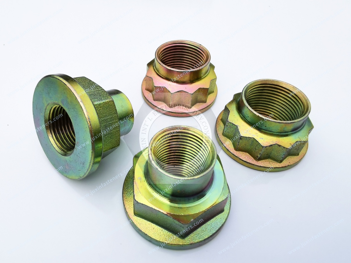
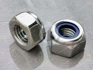
A nylon insert lock nut, commonly called a Nyloc-type nut in general industry terminology, uses a polymer insert that interferes with the mating bolt thread.
This creates prevailing torque and provides resistance to relative rotation.
Potential applications include:
Electrical cabinets
Control equipment
Industrial machinery
Mounting brackets
Equipment housings
Transportation equipment
JUXIN FASTENERS supplies DIN 985-type nylon insert lock nuts and other nylon insert locking nut configurations according to project requirements.
As the bolt thread enters the nylon insert, the polymer deforms around the thread profile.
This interference generates prevailing torque.
It is important to distinguish this from bolt preload.
Prevailing torque is not the same as clamp load.
The nylon insert creates resistance to thread rotation, while the required joint preload still depends on the tightening process and the bolted-joint design.
This distinction is important for both engineering and assembly control.
This question should not be answered with a universal yes or no.
After installation and removal, the nylon insert may no longer provide the same prevailing-torque characteristics as when new.
Reuse suitability depends on:
Product specification
Number of installation cycles
Thread condition
Temperature exposure
Chemical exposure
Required prevailing torque
Customer requirements
For controlled industrial applications, engineers should establish a reuse criterion rather than assuming indefinite reusability.
Where locking performance is critical, replacement after removal may be the more appropriate maintenance strategy depending on the governing specification.
A polymer locking element has different temperature limitations from an all-metal nut.
Engineers should therefore define:
Normal operating temperature
Maximum exposure temperature
Thermal cycling
Nearby heat sources
Abnormal operating conditions
A nylon insert lock nut should not be selected solely because vibration is present.
If temperature exceeds the capability of the locking element, another locking strategy may be required.
The acceptable temperature range should be based on the actual insert material and product specification rather than a generic assumption.
Where polymer locking elements are unsuitable, an all-metal prevailing torque lock nut may be considered depending on the application.
All-metal designs create prevailing torque through controlled metallic thread or nut geometry rather than a polymer insert.
Potential reasons to evaluate an all-metal design include:
Higher-temperature environments
Application-specific durability requirements
Restrictions on polymer components
However, all-metal lock nuts also require engineering evaluation.
Important factors can include:
Thread condition
Prevailing torque
Coating
Lubrication
Installation torque
Galling risk with certain material combinations
Reuse criteria
“All-metal” does not mean “appropriate for every severe application.”
Stainless steel lock nuts may be considered where corrosion resistance is important.
Depending on the application and product specification, options can include A2 / 304-type and A4 / 316-type stainless steel.
Potential applications include:
Outdoor electrical enclosures
Industrial equipment
Energy equipment
Corrosive environments
Stainless steel cabinet structures
Material selection should consider the actual exposure environment.
A2 / 304-type stainless steel is widely used for general corrosion-resistant industrial applications.
A4 / 316-type stainless steel contains molybdenum and can provide improved resistance in certain chloride-containing or more aggressive environments.
However, A4 / 316 should not automatically be specified for every outdoor electrical enclosure.
Engineers should consider:
Chloride exposure
Humidity
Chemicals
Temperature
Cleaning processes
Parent materials
Crevice conditions
Cost
Availability
Corrosion performance is a system-level material decision.
Stainless steel threaded fasteners can be susceptible to galling under certain assembly conditions.
Galling is an adhesive wear mechanism that can damage mating threads during tightening or removal.
Risk can be influenced by:
Material combination
Thread condition
Surface finish
Assembly speed
Lubrication
Tightening load
For stainless steel lock nut applications, engineers and production teams should consider the complete assembly process rather than focusing only on corrosion resistance.
Carbon steel lock nuts can provide an efficient solution for many indoor and protected industrial applications.
Depending on customer requirements, surface treatments may be selected to support corrosion protection and assembly requirements.
Possible coating systems can include zinc-based or other specified industrial finishes depending on the part and project.
The finish should be selected according to:
Required corrosion performance
Service environment
Mating materials
Friction requirements
Appearance
Applicable customer specification
A coating should not be selected only from its color.
Surface treatment can also affect friction during tightening.
This is important because tightening torque is converted partly into:
Thread friction
Bearing-surface friction
Bolt tension
If the friction condition changes, the relationship between applied torque and achieved preload can also change.
Therefore, changing a nut from one coating system to another without reviewing the assembly process can influence joint behavior.
This becomes especially important when procurement qualifies an alternative supplier.
A part that is dimensionally interchangeable is not necessarily assembly-process interchangeable if the friction system changes significantly.
One of the most important concepts in bolted-joint engineering is that applied torque is not itself the functional clamp load.
Torque is an installation input.
Preload is the tension created in the fastener and the resulting clamping action in the joint.
The relationship between them is affected by friction.
This means two visually identical nut-and-bolt assemblies can potentially develop different preload at the same applied torque if their:
Coatings
Lubrication
Surface conditions
Thread conditions
are different.
For critical power equipment, tightening specifications should therefore be established with the actual fastener system.
Vibration alone does not explain every loose threaded joint.
A more useful engineering question is:
Does the external loading create sufficient relative movement at the joint interface to promote self-loosening or loss of clamp condition?
Relevant factors can include:
Initial preload
Joint stiffness
Bolt stiffness
Transverse load
Interface slip
Bearing-surface settlement
Thermal cycling
Fastener geometry
Locking features can add resistance, but maintaining an appropriate joint condition remains fundamental.
Transformer and related electrical equipment can experience mechanical and thermal conditions that require careful joint design.
Potential fastening locations include:
Equipment frames
Covers
Mounting brackets
Access structures
Auxiliary assemblies
Selection factors can include:
Vibration
Thermal cycling
Mechanical loading
Corrosion
Maintenance access
Electrical requirements
Lock nuts may form part of the mechanical fastening strategy, but the specific locking method should be selected according to the actual joint.
Power distribution boxes may require threaded fastening for:
Mounting brackets
Internal supports
Covers
Equipment frames
Structural enclosure components
Auxiliary hardware
Depending on the joint, fastening options may include:
Serrated flange nuts
Nylon insert lock nuts
Stainless steel lock nuts
Conventional nuts with an engineered locking method
Rivet nuts
Self-clinching nuts
Screws and bolts
The correct solution depends on whether the connection is permanent, serviceable or part of a captive threaded attachment.
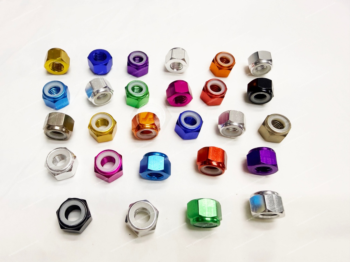
Electrical cabinets often combine several fastening technologies.
For example:
Permanent sheet-metal joints: blind rivets may be appropriate.
Reusable threads in thin sheet: rivet nuts or self-clinching nuts may be appropriate.
Bolted structural or mounting joints: conventional or locking nuts may be appropriate.
Serviceable covers: screws with suitable captive threaded hardware may be appropriate.
This is why an electrical cabinet should be designed as a fastening system, not as a collection of unrelated fasteners.
Mechanical fastening around a busbar is different from an ordinary enclosure bracket.
If the bolted connection is part of the current-carrying electrical interface, engineers must consider more than mechanical anti-loosening.
Relevant variables can include:
Contact pressure
Contact resistance
Contact surface condition
Conductive materials
Plating
Thermal cycling
Temperature rise
Creep or relaxation
Short-circuit mechanical forces
Tightening method
Applicable electrical-equipment requirements
A serrated flange nut or nylon insert lock nut should therefore not be recommended for a current-carrying busbar connection simply because it is described as “anti-loosening.”
The electrical joint must be engineered and validated as a complete system.
Some electrical equipment fasteners also form part of a protective bonding path.
In these joints, electrical continuity can be affected by:
Paint
Powder coating
Oxide layers
Plating
Contact surfaces
Serrations
Washers
Surface preparation
Corrosion
A mechanical lock nut does not by itself prove that the connection provides the required electrical bonding performance.
Where the fastener participates in grounding or protective bonding, the electrical function should be explicitly specified and validated.
This is a useful example of why mechanical and electrical requirements can conflict.
Serrations may mechanically engage the mating surface.
But if the surface is painted or powder coated, the serrations may disturb that coating.
Depending on the design, this could:
Be intentionally used to expose conductive material
Be undesirable because it damages corrosion protection
Produce inconsistent electrical contact
Change the friction condition
Therefore, engineers should not simply specify “serrated flange nut for grounding.”
The complete bonding and corrosion strategy must be defined.
The same fastening principles apply to equipment such as:
Power conversion systems
Energy-storage enclosures
Inverter housings
Electrical distribution equipment
Industrial power electronics
Renewable-energy equipment
These systems can combine:
Vibration
Thermal cycling
Outdoor exposure
Mixed materials
Serviceable components
Electrical bonding requirements
The lock nut should be selected according to the particular mechanical joint rather than only the industry name.
| Application Condition | Potential Solution | Important Check |
|---|---|---|
| General industrial vibration | Suitable prevailing-torque or locking nut | Joint movement and preload |
| Moderate-temperature serviceable joint | Nylon insert lock nut may be considered | Insert temperature and reuse |
| Higher-temperature application | Suitable all-metal system may be considered | Prevailing torque and galling |
| Integrated bearing surface desired | Flange nut | Parent surface |
| Serrated interface acceptable | Serrated flange nut | Coating and surface damage |
| General corrosion-resistant application | A2 / 304-type stainless | Actual environment |
| More aggressive chloride exposure | A4 / 316-type may be considered | Actual corrosion conditions |
| Coated carbon steel system | Suitable specified coating | Corrosion and friction |
| Electrical bonding joint | Application-specific fastening design | Electrical validation |
No row should be interpreted independently from the complete joint.
Thread-locking adhesive provides another approach to resisting unwanted thread movement.
Whether an adhesive or mechanical lock nut is more appropriate depends on factors such as:
Assembly process
Thread cleanliness
Temperature
Chemical exposure
Serviceability
Cure requirements
Production control
Maintenance strategy
For some projects, a mechanical lock nut may simplify assembly.
For others, an adhesive-based locking strategy may be specified by the equipment manufacturer.
The correct approach should follow the validated joint design.
A double-nut arrangement is sometimes used in particular mechanical applications.
However, simply adding a second nut should not be treated as a universal anti-loosening solution.
Correct performance depends on:
Assembly method
Nut geometry
Thread engagement
Tightening sequence
Joint purpose
Where space, weight, production time or repeatability matter, an engineered lock nut may offer a more practical alternative.
The choice should be based on the actual joint requirements.
A practical selection process can follow this sequence.
Is the fastener clamping:
A structural bracket?
A cabinet panel?
A removable component?
An electrical interface?
A grounding connection?
Consider:
Axial loading
Transverse loading
Vibration
Shock
Fatigue
Determine how the joint will be tightened and controlled.
This is especially important when polymer locking elements are being considered.
Consider:
Indoor or outdoor use
Humidity
Chlorides
Chemicals
Cleaning processes
Identify:
Bare metal
Zinc-plated surface
Paint
Powder coating
Stainless steel
Aluminum
Other materials
Will the nut be removed?
If so, establish inspection and reuse criteria.
Testing should represent the actual:
Bolt
Nut
Coating
Parent materials
Tightening method
Loading
Environment
The root cause may be insufficient preload, joint slip, settlement or installation variation.
An M8 lock nut description does not define locking mechanism, material, strength, coating or temperature capability.
Serrations interact with the mating surface and may damage coatings or change electrical and corrosion behavior.
The insert creates prevailing torque. Proper preload still depends on the bolted-joint design and tightening process.
Polymer locking elements have material-dependent thermal limits.
The complete corrosion environment and mating materials should be evaluated.
Corrosion-resistant material does not eliminate assembly-related thread risks.
A different friction condition can change the torque-preload relationship.
Mechanical retention, electrical bonding and current-carrying performance are separate engineering requirements.
Industrial nuts and threaded fasteners can be specified according to relevant ISO, DIN, EN, ASME/ANSI, SAE,
ASTM or customer drawing requirements, depending on the product and market.
For example, nylon insert lock nuts may be supplied in configurations corresponding to established DIN/ISO dimensional and functional requirements where applicable.
However, compliance of an individual fastener does not demonstrate compliance of the complete power distribution box, switchgear assembly or electrical system.
Equipment-level requirements may separately address:
Electrical safety
Protective bonding
Temperature rise
Short-circuit performance
Environmental protection
Vibration
Fire behavior
Ingress protection
The applicable requirements should be identified for each project.
A practical bolted-joint validation process may include:
Confirm the bolt and nut specification.
Confirm thread size and pitch.
Confirm material and strength requirements.
Confirm surface treatment.
Establish the tightening process.
Evaluate the expected preload condition.
Verify locking performance where required.
Evaluate mating-surface behavior.
Assess temperature exposure.
Assess corrosion conditions.
Evaluate vibration or cyclic loading where applicable.
Establish reuse criteria where relevant.
Validate electrical bonding separately where applicable.
Confirm production repeatability.
The validation plan should reflect the actual risk of the application.
For power distribution, electrical cabinet and industrial equipment projects, procurement and supplier-development teams should provide:
2D drawing
Nut type
Thread size and pitch
Applicable dimensional standard where required
Nut material
Required strength or property class where applicable
Locking mechanism
Surface treatment
Mating bolt specification
Tightening requirement where available
Prevailing-torque requirement where applicable
Operating temperature
Corrosion requirement
Vibration requirement where applicable
Mating-surface condition
Reuse requirement
Annual volume
Prototype or sample quantity
Packaging requirements
Current supplier or assembly problem
For alternative-supplier qualification, it is especially important to identify whether the existing issue is:
Nut rotation
Loss of preload
Thread damage
Galling
Corrosion
Coating failure
Surface damage
Assembly inconsistency
Different failure modes require different solutions.
JUXIN FASTENERS supports OEM manufacturers, procurement teams,
supplier-development engineers and equipment manufacturers requiring industrial locking nuts and related fastening components.
Relevant product capabilities include:
Nylon insert lock nuts
DIN 985-type lock nuts
Serrated flange nuts
Flange nuts
Stainless steel lock nuts
Carbon steel lock nuts
A2 / 304-type stainless steel nuts
A4 / 316-type stainless steel nuts
Rivet nuts
Self-clinching nuts
Screws and bolts
Weld nuts
Drawing-based custom fasteners
Material, surface treatment and dimensional requirements are reviewed according to the customer drawing and application.
The answer depends on the joint load, vibration, temperature, parent surface, corrosion environment, tightening process and serviceability requirements.
There is no single lock nut that is appropriate for every electrical application.
They can provide mechanical resistance at the bearing interface, but suitability depends on joint preload, mating surface, loading and whether the serrations are acceptable on the surface.
The nylon insert creates prevailing torque that resists relative thread rotation. It should not be treated as a substitute for correct joint preload and assembly control.
Reuse depends on the product specification, remaining prevailing torque, temperature history, thread condition and application requirements.
Critical applications should use a defined reuse or replacement criterion.
Material selection should be based on actual environmental exposure. 316-type stainless steel may be beneficial in certain chloride-containing environments,
but it is not automatically necessary for every outdoor application.
Under certain assembly conditions, stainless steel mating threads can experience adhesive wear. Material combination,
surface finish, assembly speed, lubrication and tightening conditions can influence the risk.
The change should be reviewed. Different surface systems can change friction, which can affect the relationship between applied tightening torque and achieved preload.
They may form part of some bonding designs, but the fastener alone does not establish compliant electrical continuity.
Surface coatings, contact geometry, corrosion and applicable electrical requirements must also be evaluated.
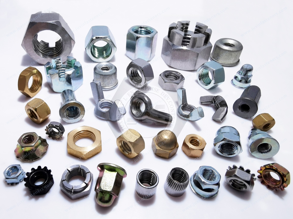
Yes. JUXIN FASTENERS supports standard and drawing-based fastener projects according to customer dimensions, materials,
surface treatments, mechanical requirements and purchasing volumes.
Selecting a lock nut should not begin with:
“Which nut will never loosen?”
No locking nut can make every bolted joint immune to all failure mechanisms.
A more useful engineering path is:
Joint Function → Load → Preload → Movement → Locking Mechanism → Temperature → Surface → Corrosion → Installation → Validation
Once those conditions are defined, engineers and procurement teams can determine whether the application requires a nylon insert lock nut,
serrated flange nut, all-metal lock nut, stainless steel nut, coated carbon steel nut or another engineered fastening strategy.
For power distribution, switchgear, transformer, control cabinet or industrial electrical equipment projects, send JUXIN FASTENERS your 2D drawing,
thread specification, material, strength requirement, surface treatment, operating conditions and annual volume.
Email: info@juxinfasteners.com
Website: www.juxinfasteners.com
Use the existing indexed JUXIN FASTENERS URL when implementing these internal links:
Rivet Nuts for Electrical Cabinets, Switchgear & Control Panels
Railway Converter Cabinet Fastening Solutions
Rivets vs Screws vs Rivet Nuts: Industrial Fastening Method Selection
Nylon Insert Lock Nuts Engineering Guide
Serrated Flange Nuts for Industrial Applications
Stainless Steel Lock Nuts
Self-Clinching Nuts and Studs
Power Electronics Fastening Solutions
Industrial Automation Fastening Solutions
Custom Fasteners and Drawing-Based Components
 MORE NEWS
Oct. 13, 2026
Contact Us
Tel.:
+86 020 8621 0320
+86 020 3121 6067
E-mail:
Technical Support:
Navigation
SEND INQUIREY