
Call Us
+86 136 6007 9809
Call Us
+86 136 6007 9809

Oct. 15, 2023
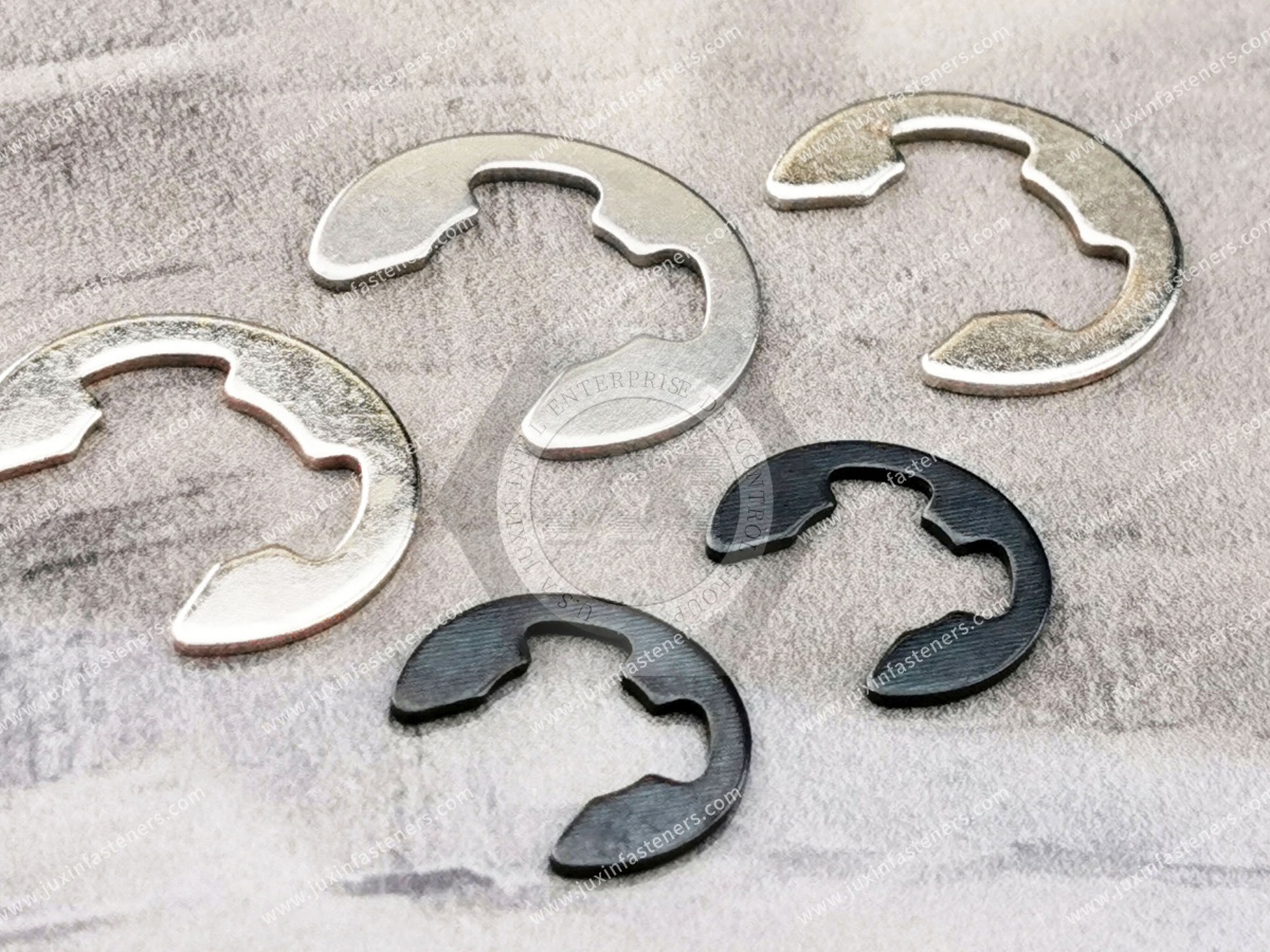
E-type retaining rings, commonly called E-clips or E-rings, are compact radial-installation fasteners used to provide axial retention on grooved shafts.
Their distinctive E-shaped geometry allows the retaining ring to be pushed radially into a machined shaft groove rather than expanded over the end of the shaft like many conventional external circlips.
This installation method makes E-type retaining rings particularly useful in compact mechanical assemblies,
high-volume production and applications where access to the end of the shaft is restricted or inconvenient.
E-clips are widely used to retain components such as gears, rollers, bushings, levers, linkages, wheels and other mechanical parts.
However, selecting an E-clip should not be based only on nominal shaft diameter.
For a reliable industrial assembly, engineers and procurement teams should evaluate the complete retention system:
E-Clip + Shaft Groove + Retained Component + Shaft Material + Axial Load + Installation Process + Operating Environment
Understanding this relationship is important for both new product design and OEM second-source development.
An E-type retaining ring is a spring fastener designed to engage a circumferential groove machined into a shaft.
The ring is normally installed radially from the side of the shaft.
As the E-clip is pushed into the groove, its internal retaining features elastically deflect around the groove region and then recover sufficiently to hold the ring in position.
Once installed, the outer portion of the ring projects beyond the shaft groove and forms an axial stop for the retained component.
Depending on regional terminology and purchasing practices, these components may be searched as:
E-type retaining rings
E-clips
E-rings
E-type circlips
E-type snap rings
Shaft E-clips
External retaining clips
Radial retaining rings
Shaft retaining clips
Spring retaining clips
For sourcing purposes, the drawing, applicable standard and groove dimensions should take precedence over terminology alone.
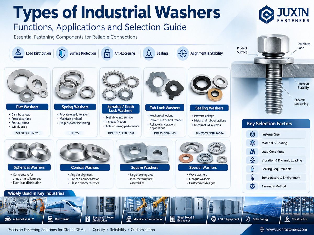
Both E-clips and conventional external circlips can provide axial retention on shafts, but their installation architecture is different.
A conventional external circlip is commonly expanded and installed axially over the end of the shaft before being released into its groove.
An E-clip is normally installed radially from the side.
This difference can significantly affect product and assembly design.
Typical characteristics include:
Radial installation
No requirement to pass the ring over the shaft end
Compact axial package
Suitable for automated or high-volume assembly
Useful where shaft-end access is restricted
Rapid installation when the assembly is designed appropriately
Typical characteristics include:
Axial installation from the shaft end
Expansion during installation
Circlip pliers or suitable installation tooling
Broad range of shaft-retention applications
Standardized configurations such as DIN 471 where applicable
Neither architecture is universally better.
The correct choice depends on the shaft, groove, retained component, load, available installation access and production process.
A common engineering question is whether an E-clip can replace a DIN 471 external retaining ring.
The answer depends on the application.
Although both are used on shafts, they have different geometry and installation behavior.
A DIN 471 retaining ring normally surrounds most of the shaft circumference and is expanded during installation.
An E-clip enters the groove radially.
Therefore, converting between these designs can affect:
Groove geometry
Axial retention capability
Installation tooling
Assembly sequence
Available radial space
Service removal
Component contact geometry
An E-clip should not automatically be substituted for a conventional external circlip solely because the nominal shaft diameter is similar.
Engineering approval should be based on the actual assembly requirements.
The primary function of an E-type retaining ring is axial retention.
When the retained component moves axially toward the clip, the load is transferred through the assembly approximately as:
Retained Component → E-Clip → Groove Edge → Shaft
This means the retaining capability of the system is not determined by the E-clip alone.
The groove and shaft are structural parts of the retention system.
A correctly manufactured E-clip can still perform poorly if the shaft groove is incorrect.
Important groove characteristics may include:
Groove diameter
Groove width
Groove depth
Groove location
Groove edge condition
Groove tolerance
Surface finish
Distance from adjacent shoulders
Shaft material
Shaft hardness
Burrs, incorrect groove dimensions or poor groove positioning can prevent proper seating or reduce retention performance.
For this reason, groove inspection should be part of troubleshooting when an E-clip installation problem occurs.
A request such as:
“Please quote an E-clip for a 10 mm shaft.”
does not completely define the required component.
Two assemblies using the same nominal shaft diameter may use different:
Groove diameters
Groove widths
Ring thicknesses
Retention requirements
Materials
Surface finishes
Installation processes
For reliable sourcing, the applicable standard or drawing should be supplied whenever possible.
Engineers selecting E-type retaining rings should evaluate several interacting variables.
The ring must be compatible with the actual groove rather than merely the nominal shaft diameter.
The expected load acting against the retaining ring must be considered.
The groove edge must be capable of supporting the transferred load without unacceptable deformation.
The geometry contacting the E-clip influences how load reaches the ring.
The assembly must provide sufficient radial access for installation.
Serviceability can influence the preferred retaining architecture.
Temperature, corrosion, contamination and chemical exposure can affect material and finish selection.
High-volume applications may benefit from dedicated installation tooling or automated feeding and insertion systems.
One of the most important engineering principles is that the retention capability belongs to the complete assembly.
Potential limiting factors include:
E-Clip Strength
The clip must resist unacceptable deformation or disengagement.
Groove Strength
The groove edge must transfer the applied axial load.
Shaft Material
A soft shaft material can deform even when the retaining ring itself remains intact.
Retained Component Geometry
The component must contact the E-clip appropriately.
Installation Quality
A partially seated clip may not provide the intended retention.
The weakest element can determine the practical performance of the system.
E-type retaining rings may be used in suitable bearing-related assemblies where the geometry and load permit.
However, several factors should be reviewed.
Bearing rings commonly have chamfers or radii near their edges.
The E-clip and adjacent component geometry should therefore be checked to ensure the intended surfaces carry the axial load.
An E-clip creates an axial stop but does not automatically create zero-clearance positioning.
Final axial clearance depends on the tolerance stack involving:
Shaft shoulder
Bearing width
Groove location
E-clip thickness
Spacers or washers where used
For higher axial loads, the complete retention system should be evaluated rather than assuming any E-clip of the correct diameter is sufficient.
E-clips can also retain gears, pulleys, rollers and similar shaft-mounted components.
In these applications, the E-clip normally provides axial retention.
It should not automatically be considered the component responsible for transmitting operating torque.
Torque may instead be transmitted through:
Keys
Splines
Flats
Interference fits
Pins
Geometric engagement
Other dedicated drive features
This distinction prevents the retaining ring from being incorrectly sized for a function it was not intended to perform.
E-type retaining rings require materials capable of controlled elastic deformation during installation and reliable recovery after seating.
Depending on the product specification, material families may include:
Carbon spring steel
Alloy spring steel
Stainless steel
Application-specific spring materials
Material selection should consider:
Required elasticity
Mechanical strength
Fatigue conditions
Corrosion exposure
Temperature
Installation deformation
Surface treatment
Customer specification
The exact material should be confirmed against the applicable standard or approved drawing.
Spring steels are commonly used for E-type retaining rings because properly processed material can provide the elastic characteristics required for installation and retention.
Performance depends on several manufacturing variables:
Material condition
Forming process
Heat treatment
Hardness
Dimensional control
Edge condition
Surface treatment
Material designation alone does not define finished E-clip performance.
Stainless steel E-clips may be selected where improved corrosion resistance is required.
Common industrial stainless steel families may include A2 / 304-type and A4 / 316-type materials where appropriate to the specification.
Potential applications include:
Food-service equipment
HVAC equipment
Medical and laboratory equipment
Telecommunications equipment
Electrical equipment
Instruments and meters
Semiconductor equipment
Outdoor mechanical assemblies
However, stainless steel should not be described as universally resistant to acids, alkalis, salts or all chemical environments.
Material suitability depends on the actual chemical, chloride, temperature and exposure conditions.
Carbon and alloy steel E-clips may use different surface-protection systems according to customer and environmental requirements.
Possible finish families include suitable:
Phosphate and oil systems
Black finishes
Zinc-based coatings
Zinc-nickel coatings
Zinc-flake systems
Other engineered protective coatings
Selection should consider:
Corrosion requirement
Product hardness
Hydrogen-embrittlement risk where applicable
Coating thickness
Groove fit
Installation behavior
Environmental compliance requirements
E-clips engage closely controlled shaft grooves.
Changing a surface treatment can alter:
Finished thickness
Surface friction
Installation force
Groove engagement
Corrosion performance
Removal behavior
A coating change should therefore not automatically be treated as a cosmetic substitution.
For OEM programs, dimensional and functional validation may be required.
Unlike conventional external circlips, E-clips are generally not installed by expanding the ring with external circlip pliers.
They are normally pushed radially into the shaft groove using appropriate tooling.
Depending on production volume, installation may use:
Manual E-clip installation tools
Applicators
Dedicated assembly fixtures
Pneumatic installation systems
Automated feeding and insertion equipment
The correct tooling depends on clip size, shaft geometry, access and production requirements.
A practical installation sequence is:
Confirm the E-clip corresponds to the required drawing or specification.
Check for:
Burrs
Damage
Contamination
Incorrect machining
Coating buildup
Position the clip squarely with the groove.
Push the E-clip into the groove using suitable tooling.
Confirm that the clip is fully engaged and not visibly distorted.
Check that the component has the intended axial position and clearance.
E-clips are particularly useful in high-volume manufacturing because radial installation can be compatible with automated assembly processes.
A production system may incorporate:
Bulk E-Clips → Feeding → Orientation → Shaft Positioning → Radial Insertion → Seating Verification
This can be relevant in automotive components, appliances, electronic equipment, actuators and other repetitive mechanical assemblies.
When automation is planned, engineers should consider installation tooling during product design rather than after the shaft and groove geometry have already been finalized.
E-clips can often be removed using suitable removal tools, but uncontrolled prying should be avoided.
During removal, the clip can release stored elastic energy and move suddenly.
Appropriate eye protection and controlled tooling are recommended for manual service work.
The removal method should minimize damage to:
E-clip
Shaft groove
Adjacent components
Surface coating
Reuse should not automatically be assumed.
Removal can alter:
Clip geometry
Elastic behavior
Surface finish
Edge condition
For safety-critical, high-load or controlled OEM assemblies, replacement with a new retaining ring may be required by the applicable service or engineering specification.
The decision should follow the product and equipment requirements rather than a universal reuse rule.
E-type retaining rings are widely applicable to compact mechanical mechanisms in automotive systems.
Potential applications include suitable:
Seat mechanisms
Linkages
Actuators
Small gear mechanisms
Pedal assemblies
Latch mechanisms
Wiper mechanisms
Auxiliary motors
Pump mechanisms
Automotive programs may require additional controls for dimensional consistency, traceability, material and surface treatment according to the project.
In EV and battery-related systems, E-clips may be used in suitable mechanical mechanisms associated with:
Pumps
Thermal-management equipment
Actuators
Cooling systems
Production automation
Fixtures
Handling equipment
The application should be evaluated according to the mechanical assembly rather than assuming a generic “EV-grade” retaining ring.
Radial installation makes E-clips useful in compact mechanical assemblies found in:
Robotic joints
Actuators
Grippers
Linkages
Gear mechanisms
Conveyors
Automated handling systems
Assembly equipment
For high-cycle applications, fatigue, groove wear and dimensional consistency may require additional engineering consideration.
Potential applications include:
Packaging equipment
Processing machinery
Small gear assemblies
Rollers
Linkages
Actuators
Material-handling equipment
Machine mechanisms
The correct retaining architecture depends on the actual load and assembly configuration.
E-type retaining rings may be used in suitable:
Door mechanisms
Actuators
Auxiliary equipment
Seat mechanisms
Control mechanisms
Maintenance equipment
Rail projects may impose additional customer-specific requirements for documentation, vibration, fatigue, traceability or material control.
Potential applications include:
Fan mechanisms
Blowers
Motors
Pumps
Actuators
Valve mechanisms
Cooling equipment
Humidity, condensation and temperature should be considered when selecting material and finish.
High-density computing infrastructure is increasing the use of pumps, fans, motors, actuators and liquid-cooling equipment.
E-clips may provide compact axial retention in suitable mechanical subassemblies within:
Cooling distribution units
Pumps
Fans
Motors
Valve actuators
Liquid-cooling equipment
The ring specification should be determined from the actual shaft, groove, load and environment.
E-clips may be used in mechanical components such as:
Fans
Small motors
Actuators
Mechanical interlocks
Switch mechanisms
Cabinet hardware
Their function in these assemblies is mechanical retention rather than electrical grounding unless a separate engineered function has been specifically validated.
Potential applications include:
Antenna mechanisms
Base-station equipment
Cooling fans
Motors
Adjustment mechanisms
Actuators
Outdoor communication hardware
For outdoor applications, corrosion exposure should be considered during material and coating selection.
E-clips may be used in suitable mechanical assemblies within:
Automation equipment
Robotics
Material handling
Motion-control systems
Pumps
Actuators
Positioning equipment
Standard industrial E-clips should not automatically be represented as cleanroom- or vacuum-qualified.
Such requirements must be defined and validated separately.
E-type retaining rings can be used in suitable mechanical assemblies within:
Commercial mixers
Dispensing equipment
Refrigeration systems
Pumps
Motors
Processing equipment
Conveyor mechanisms
Material selection should consider washdown, humidity and cleaning chemicals where applicable.
Use in food-service machinery does not automatically mean the E-clip is approved for direct food contact.
Potential non-implant applications include:
Diagnostic equipment
Laboratory automation
Pumps
Motors
Actuators
Positioning systems
Sample-handling mechanisms
Customer-specific requirements for material, cleanliness, documentation and traceability should be evaluated separately.
Small E-clips are particularly useful in compact mechanical assemblies such as:
Measuring instruments
Adjustment mechanisms
Indicators
Small shafts
Linkages
Sensor mechanisms
Precision mechanical devices
Tolerance stack-up and installation consistency can be especially important in miniature assemblies.
E-clips are frequently compatible with high-volume mechanical assemblies involving:
Motors
Fans
Hinges
Rollers
Linkages
Control mechanisms
Rotating components
Their radial installation can support efficient production when the product and assembly tooling are designed together.
Suitable applications may include:
Ground-support equipment
Test equipment
Manufacturing tooling
Laboratory equipment
Automation systems
Non-flight-critical mechanical assemblies
unless a specific aerospace program establishes additional qualification requirements.
A standard commercial E-clip should not automatically be represented as aerospace-qualified.
Understanding potential failure modes improves both product design and supplier troubleshooting.
Possible causes include:
Incorrect clip
Incorrect groove
Excessive axial load
Incomplete seating
Clip deformation
Shaft deformation
Possible causes include:
Excessive axial load
Soft shaft material
Incorrect groove geometry
Insufficient edge support
Possible causes include:
Incorrect E-clip size
Incorrect groove
Burrs
Coating buildup
Misalignment
Unsuitable tooling
Possible causes include:
Groove position
Clip thickness
Retained-component tolerance
Shoulder position
Assembly stack-up
Possible causes include:
Unsuitable material
Inadequate coating
Moisture
Chlorides
Cleaning chemicals
Environmental exposure
Failure analysis should evaluate the complete retention system rather than the E-clip alone.
A practical engineering selection sequence is:
Is the component retained on a shaft?
→ Yes.
Can the retaining ring be installed radially?
→ If yes, evaluate an E-type retaining ring.
Is shaft-end installation preferable or required?
→ Evaluate a conventional external retaining ring such as an applicable DIN 471 configuration.
For an E-clip application, continue with:
Shaft Diameter → Groove Geometry → Axial Load → Shaft Material → Retained Component
→ Axial Clearance → Installation Access → Service Requirements → Environment → Material → Surface Finish → Validation
This approach is more reliable than selecting an E-clip from shaft diameter alone.
E-clip search behavior differs significantly between engineering and purchasing teams.
Engineers may search for:
E-clip groove dimensions
E-ring for shaft
E-clip vs circlip
E-clip axial load
E-clip installation
E-clip for bearing
E-clip for gear
radial retaining ring
retaining clip for shaft
Their core question is:
Will this E-clip architecture work in my assembly?
Procurement teams may search for:
E-clip manufacturer
E-clip supplier
E-ring supplier
stainless steel E-clips
spring steel E-clips
custom E-clip manufacturer
E-clip OEM supplier
E-clip second source
E-clips from drawing
Their core question is:
Can the supplier consistently manufacture the required clip and support production?
A strong industrial sourcing page should address both.
Standard E-type retaining rings are often the most economical solution when the assembly is designed around established dimensions.
Custom or modified E-clips may be required when the application has:
Non-standard shaft diameter
Existing non-standard groove
Special ring thickness
Restricted radial envelope
Modified contact geometry
Special material
Special coating
Customer-specific retention requirements
Legacy component replacement
The project should therefore be classified before quotation as:
Standard E-Clip
Standard-Based Modified E-Clip
Exact Drawing Replacement
Functional Equivalent
Custom E-Type Retaining Ring
When an existing product must be sourced but the original drawing is unavailable, a physical sample can support development.
A typical process is:
Sample → Dimensional Inspection → Groove Review → Application Review → Material / Finish Evaluation → Drawing Confirmation → Prototype → Assembly Test → Production
A sample can reveal geometry.
It may not reveal the original:
Material specification
Heat-treatment requirement
Hardness target
Coating specification
Design axial load
Fatigue requirement
Original engineering standard
Application data therefore remains important.
For efficient engineering review and quotation, provide as much of the following information as available.
Applicable standard
Customer drawing
Customer part number
Physical sample
Required E-clip type
Nominal shaft diameter
Groove diameter
Groove width
Groove location
Shaft material
Shaft hardness where relevant
Bearing
Gear
Pulley
Roller
Bushing
Lever
Linkage
Other component
Expected axial load
Static or dynamic loading
Vibration
Shock
Required service life
Acceptable axial clearance
Required material
Hardness where specified
Surface finish
Corrosion requirement
Restricted-substance requirements
Operating temperature
Humidity
Outdoor exposure
Chlorides
Cleaning chemicals
Other relevant media
Sample quantity
Pilot quantity
Production quantity
Estimated annual usage
Packaging requirements
Traceability requirements
Delivery schedule
For OEM, Tier-1, Tier-2 and industrial programs, supplier evaluation can extend beyond unit price.
Depending on the project, relevant capabilities may include:
Drawing review
Material control
Forming-process control
Heat-treatment control where applicable
Dimensional inspection
Surface-treatment control
Prototype development
Production consistency
Automatic optical sorting where applicable
Lot identification
Packaging
Change management
Long-term supply support
For high-volume E-clips, automated inspection can support suitable dimensional and visual characteristics, but inspection methods should be matched to the actual product requirement.
JUXIN FASTENERS supports E-type retaining rings, E-clips, E-rings, shaft retaining rings and custom retaining-ring projects for industrial OEMs,
engineering teams, purchasing organizations, supplier-development teams and global supply chains.
Projects can be evaluated from:
Applicable standard
2D drawing
Physical sample
Shaft dimensions
Groove dimensions
Material requirement
Surface-finish requirement
Application information
Production quantity
Depending on the project, the sourcing path may involve:
Standard E-Clip → Drawing-Based Replacement → Modified E-Clip → Custom E-Type Retaining Ring
Where the application may be better suited to another retaining architecture, the project can also be evaluated against external shaft retaining rings or other appropriate retaining-ring configurations.
A useful sourcing process starts with the assembly rather than the catalog number:
What is being retained?
→ What is the shaft diameter?
→ What is the groove geometry?
→ What axial load reaches the clip?
→ What is the shaft material?
→ What axial clearance is acceptable?
→ Is radial installation required?
→ How will the E-clip be installed in production?
→ Does the assembly require service removal?
→ What material and surface finish are required?
→ What environmental conditions apply?
→ Is a standard E-clip available?
→ Is an exact replacement or custom design required?
→ How will samples be validated?
→ What are the pilot and production quantities?
This converts a generic inquiry such as:
“Please quote E-clips.”
into an actionable engineering RFQ:
“Please evaluate the appropriate E-type retaining ring, groove compatibility, material and finish for this shaft assembly and required axial retention.”
For E-type retaining rings, E-clips, E-rings, spring steel E-clips, stainless steel E-clips, standard shaft retaining clips,
drawing-based replacement parts, custom E-type retaining rings or second-source development, send your drawing, sample, shaft and groove dimensions, material, finish, application requirements and quantity to:
JUXIN FASTENERS can review the available technical information and evaluate an appropriate manufacturing, sampling and production path for your project.
 MORE NEWS

Sep. 27, 2026

Sep. 27, 2026

Sep. 27, 2026
Contact Us
Tel.:
+86 020 8621 0320
+86 020 3121 6067
E-mail:
Technical Support:
Navigation
SEND INQUIREY