
Call Us
+86 136 6007 9809
Call Us
+86 136 6007 9809

Aug. 15, 2026
Expansion Bolt Solutions for Power Generation and Electrical Infrastructure
Engineering Selection, Substation Equipment Anchoring, Corrosion Protection, Seismic Considerations and OEM Fastening Solutions
Power generation and electrical infrastructure require fastening systems that maintain mechanical reliability throughout demanding operating and environmental conditions.
Substations, power distribution facilities, transformer installations, industrial power plants,
renewable energy facilities and electrical equipment rooms contain numerous components that must be securely connected to concrete foundations or other suitable supporting structures.
Expansion bolts, mechanical concrete anchors and industrial fastening components may be used for suitable post-installed connections involving equipment bases,
cable supports, electrical cabinets, steel brackets and auxiliary structures.
Unlike ordinary building installations, electrical infrastructure may involve long service periods, restricted maintenance access, outdoor corrosion exposure,
equipment vibration, seismic requirements and project-specific quality documentation.
For electrical equipment manufacturers, EPC contractors, structural engineers, mechanical engineers and procurement teams,
the correct anchoring solution depends on more than nominal bolt diameter or steel strength.
The complete connection must be evaluated, including the equipment, base plate, concrete substrate, anchor group, installation conditions and applicable technical qualifications.
Juxin Fasteners supplies industrial fastening components for power, electrical, machinery, construction and OEM applications.
Our product scope includes expansion bolts, concrete anchoring hardware, bolts, nuts, washers, sheet-metal fasteners and drawing-based custom components.
This guide examines engineering selection and procurement considerations for expansion bolt solutions in power generation and electrical infrastructure.
What Are Expansion Bolts for Electrical Infrastructure?
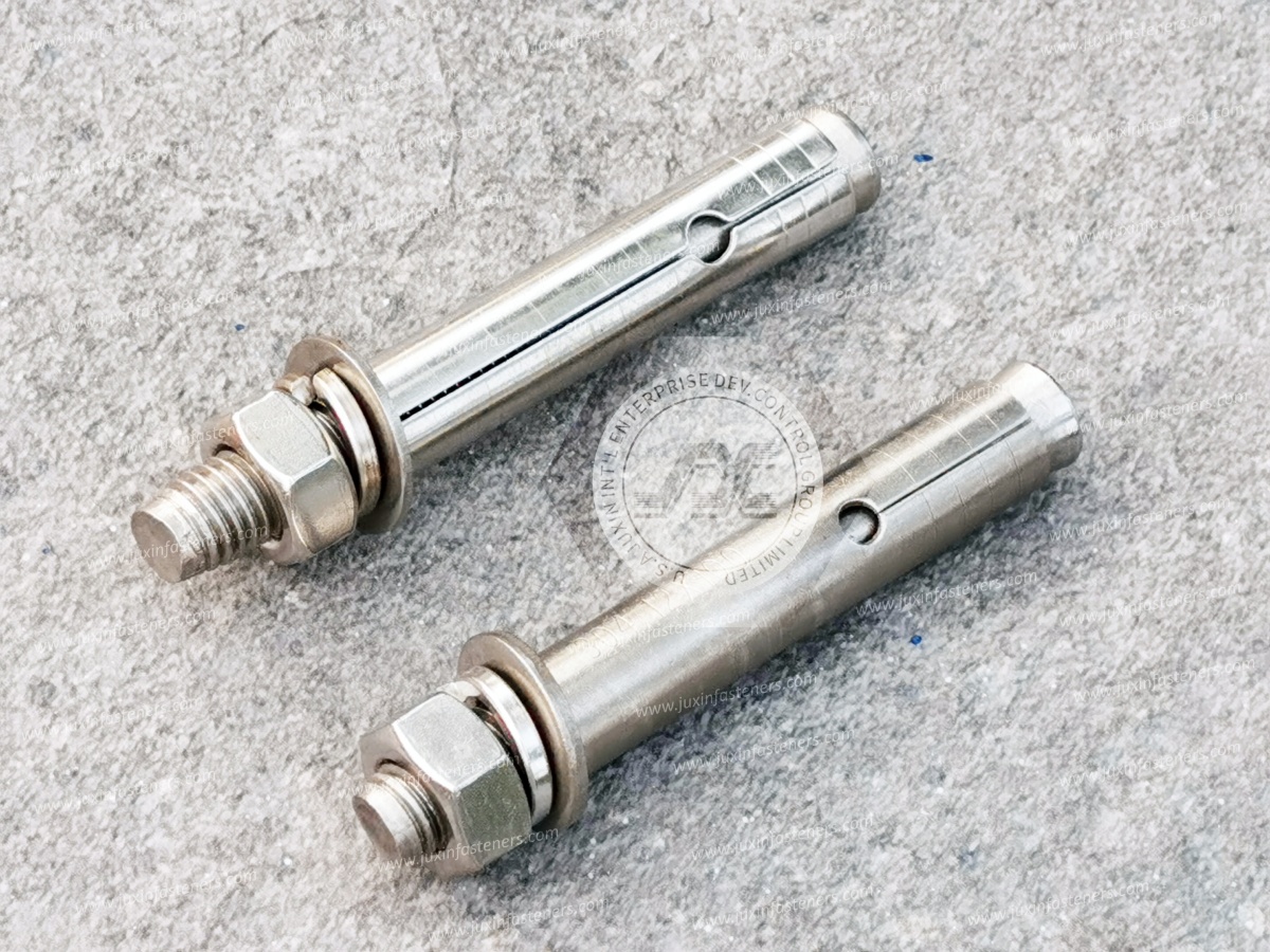
Expansion bolts are post-installed mechanical anchors that develop mechanical engagement with suitable concrete or another approved base material through an expanding component.
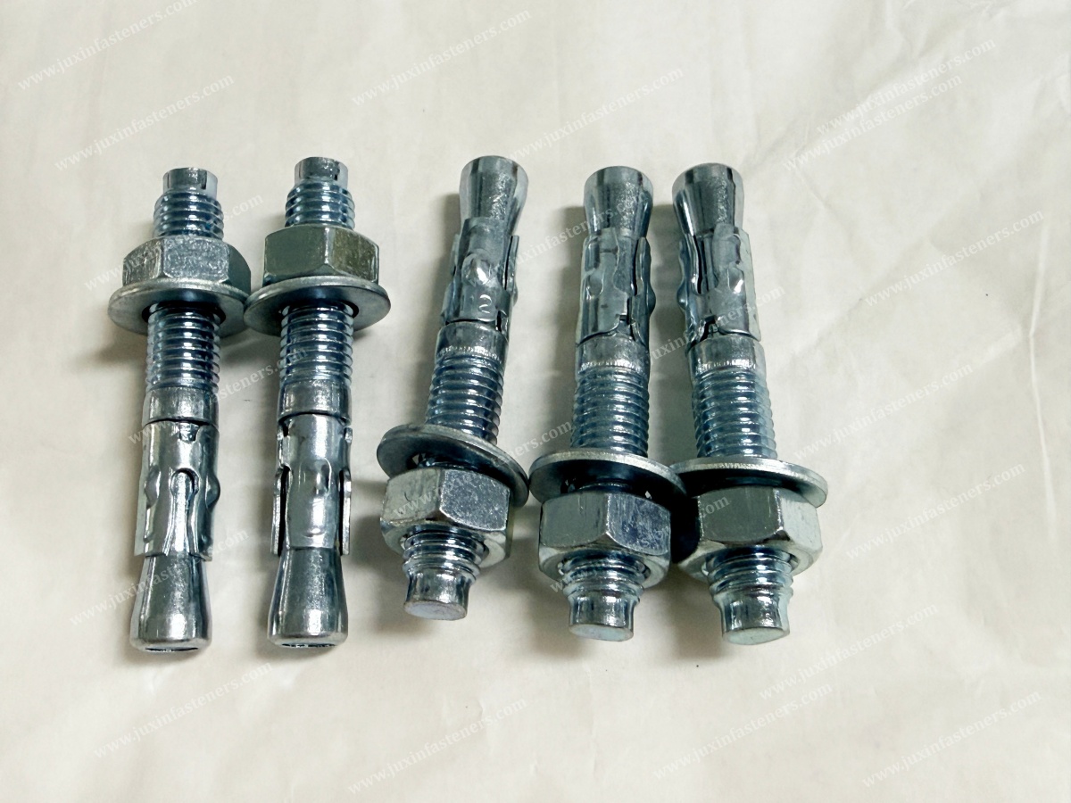
Depending on the anchor design, the assembly may include:
Threaded stud or bolt
Expansion clip or sleeve
Tapered wedge or cone
Nut and washer
Product-specific setting components
The expansion mechanism is activated according to the manufacturer's installation instructions.
The resulting connection transfers applicable tensile and shear forces from the attached fixture into the concrete.
Common International Product Terms
Engineers and industrial buyers may search for:
Power infrastructure expansion bolts
Electrical equipment concrete anchors
Substation equipment anchors
Mechanical expansion anchors
Heavy-duty concrete anchors
Wedge anchor bolts
Sleeve expansion anchors
Post-installed concrete anchors
Transformer support anchors
Electrical cabinet anchoring hardware
Cable tray concrete anchors
Industrial electrical support fasteners
These terms describe related fastening applications but do not establish technical interchangeability.
Mechanical expansion anchors, concrete screw anchors, bonded anchors and cast-in foundation bolts use different installation and load-transfer mechanisms.
Applications in Power Generation and Electrical Infrastructure
Potential applications include:
Substation equipment support frames
Transformer auxiliary supports
Electrical cabinet bases
Switchgear support structures
Cable trays and cable ladders
Conduit support systems
Electrical equipment brackets
Power distribution equipment
Industrial power plant auxiliary equipment
Maintenance structures
Renewable energy electrical equipment
Battery energy storage system accessories
UPS and power conversion equipment supports
Not every application requires an expansion bolt, and not every expansion bolt is suitable for these installations.
Power Infrastructure Application Matrix
| Application | Potential anchoring requirement | Main engineering consideration |
|---|---|---|
| Substation equipment | Equipment support to concrete | Loading, corrosion and seismic requirements |
| Transformer accessories | Auxiliary bracket or frame fixing | Equipment movement and foundation design |
| Electrical cabinet | Cabinet or support base fixing | Overturning and base plate geometry |
| Switchgear equipment | Mechanical restraint | Equipment qualification and anchorage |
| Cable tray system | Support bracket fixing | Repeated installation and overhead safety |
| Power plant equipment | Auxiliary equipment support | Vibration and operating environment |
| Solar inverter equipment | Cabinet or support fixing | Outdoor exposure and equipment geometry |
| Battery storage facility | Enclosure or auxiliary support | Mechanical safety and environmental conditions |
| UPS equipment | Equipment base anchoring | Stability, access and seismic requirements |
Important Engineering Boundary
General-purpose expansion bolts must not automatically be specified for critical transformers, high-voltage equipment,
seismic-qualified switchgear, generator foundations or other safety-sensitive electrical installations.
Such applications may require specifically evaluated anchors and engineered equipment anchorage.
Expansion Bolts for Substation Equipment
Substations contain equipment and supporting structures that must maintain mechanical stability under operating and environmental conditions.
Potential applications include:
Electrical equipment support frames
Auxiliary steel structures
Cable support systems
Control cabinets
Equipment brackets
Maintenance structures
Service platforms
Selected equipment base plates
Outdoor Environmental Exposure
Substation equipment may experience rain, condensation, humidity, atmospheric pollutants and temperature changes.
Equipment Loading
Loads may include equipment weight, wind, seismic actions and operational forces.
Concrete Conditions
Existing or new concrete foundations must satisfy the selected anchor's requirements.
Electrical Clearances
Mechanical supports must not compromise required electrical clearances or equipment access.
Maintenance
Anchor locations should permit required inspection and servicing.
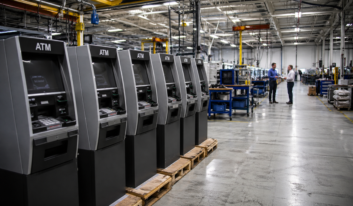
Information Gain: Equipment Anchoring and Electrical Clearances Must Be Coordinated
An anchor layout that appears structurally suitable may still interfere with cable entry, grounding conductors, inspection panels or required electrical clearances.
Electrical and structural drawings should be reviewed together before finalizing the fastening arrangement.
Transformer Support Anchoring
Transformers may be installed on concrete foundations or engineered support structures.
Potential fastening requirements include:
Auxiliary brackets
Equipment accessories
Cable management supports
Monitoring equipment
Secondary support frames
Selected equipment restraints
Primary transformer anchorage is a specialized engineering application.
Transformer Weight
The equipment weight and center of gravity influence the foundation design.
Seismic Actions
In seismic regions, transformer movement and anchorage performance may require specific assessment.
Vibration
Certain transformers can generate operational vibration.
Thermal Movement
Temperature changes may influence equipment and connection behavior.
Foundation Geometry
Existing foundations may have limited anchor spacing, edge distance or available embedment.
Information Gain: Transformer Anchorage Is Not Determined by Weight Alone
Overturning, seismic displacement, connection stiffness and equipment configuration may govern the design.
The complete transformer installation must be evaluated rather than selecting an anchor solely from a static weight estimate.
Expansion Bolts for Electrical Cabinets and Switchgear
Electrical cabinets and switchgear assemblies may require mechanical fixing to floors, plinths or support structures.
Potential applications include:
Control cabinets
Power distribution cabinets
Industrial electrical enclosures
Switchgear support frames
Auxiliary control equipment
Electrical monitoring systems
Cabinet Geometry
Tall, narrow cabinets may create overturning demands under lateral loading.
Base Plate and Mounting Holes
Mounting-hole geometry and base stiffness affect anchor force distribution.
Floor Construction
The supporting slab must have sufficient capacity and suitable anchor geometry.
Access Requirements
Anchors should not obstruct cable entry, maintenance access or equipment removal.
Seismic Requirements
Some electrical equipment installations require qualified seismic restraint systems.
Engineering Information Gain: A Cabinet Mounting Hole Is Not an Anchor Design
The presence of mounting holes in an electrical enclosure does not establish that any expansion bolt of matching diameter will be suitable.
The engineer must verify the equipment anchorage forces, foundation conditions and installation requirements.
Cable Tray and Cable Ladder Anchoring
Power infrastructure frequently requires extensive cable management systems.
Applications include:
Cable trays
Cable ladders
Conduit supports
Cable support brackets
Electrical service frames
Utility support channels
Repeated Fixing Points
Large installations may require numerous anchors.
Load Distribution
The cable weight, support spacing and bracket geometry influence the loads.
Thermal Expansion
Long cable support systems may require movement allowances.
Overhead Installation
Suspended or overhead supports require appropriate engineering and installation controls.
Corrosion
Outdoor or humid installations may require corrosion-resistant systems.
Fire and Circuit Integrity
Some cable installations have project-specific fire-resistance or circuit-integrity requirements.
Information Gain: Cable Support Design Must Consider Future Cable Loading
An initially lightly loaded cable tray may later receive additional cables.
The support design should follow the specified loading and allowance requirements rather than assuming the initial installation represents the maximum service condition.
Cable Support Selection Matrix
| Support type | Potential issue | Engineering consideration |
|---|---|---|
| Wall-mounted tray bracket | Bending moment | Anchor tension and shear |
| Suspended cable tray | Overhead loading | Qualified anchor and installation |
| Cable ladder support | Repeated support points | Standardized installation |
| Outdoor cable support | Corrosion | Material and coating selection |
| High-voltage cable support | Cable forces | System-specific restraint design |
| Fire-critical cable route | Elevated temperature | Required fire performance |
Important Limitation
Mechanical expansion anchors should not be represented as providing fire resistance or circuit integrity unless the actual anchoring arrangement has appropriate supporting evidence.
Expansion Anchors for Power Generation Facilities
Power generation facilities may include:
Gas-fired power plants
Steam power stations
Hydroelectric facilities
Industrial cogeneration systems
Renewable energy facilities
Auxiliary electrical equipment installations
Potential fastening applications include:
Electrical cabinets
Cable support frames
Auxiliary equipment brackets
Instrumentation supports
Maintenance structures
Service platforms
Selected equipment foundations
Operating Vibration
Power generation equipment may produce dynamic loads.
Temperature
Some locations experience elevated temperatures or significant temperature changes.
Maintenance Access
Fastening systems may be located near operating equipment with limited access.
Corrosion Exposure
Moisture, chemicals and industrial atmospheric conditions may affect material selection.
Engineering Information Gain: Generator Foundations Require Specialized Design
Large generators and rotating equipment may require engineered dynamic foundations and foundation bolts.
Ordinary post-installed expansion anchors should not automatically replace the specified foundation anchorage.
Expansion Bolt Solutions for Renewable Energy Facilities
Renewable energy installations contain numerous electrical and mechanical support systems.
Potential applications include:
Solar inverter cabinets
Electrical distribution enclosures
Cable support systems
Battery storage auxiliary equipment
Monitoring systems
Electrical equipment brackets
Maintenance structures
Solar Energy Infrastructure
Suitable concrete anchors may be considered for certain electrical equipment bases and auxiliary supports.
However, photovoltaic module mounting systems, ground screws and specialized solar foundation systems must be evaluated according to their own requirements.
Wind Energy Facilities
Wind power installations may require specialized structural and fatigue-sensitive anchoring systems.
Ordinary expansion bolts should not automatically be used for wind turbine tower foundations or other primary structural connections.
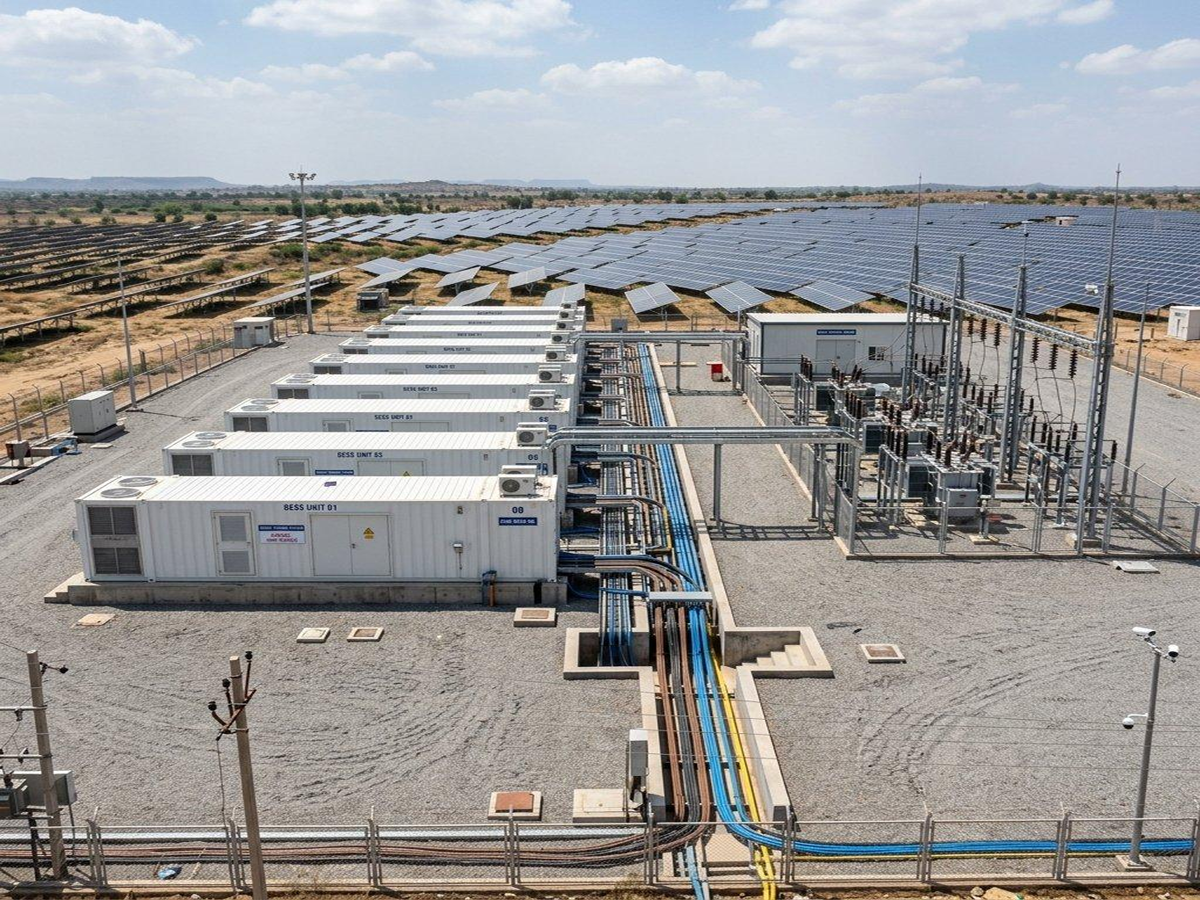
Battery Energy Storage Systems
BESS installations may require anchoring of equipment enclosures, electrical cabinets and auxiliary support structures.
Mechanical anchoring should be coordinated with:
Equipment dimensions
Structural loading
Environmental exposure
Thermal management equipment
Maintenance access
Electrical clearances
Fire and safety requirements
Information Gain: BESS Mechanical Anchoring Does Not Establish Battery Safety Compliance
A suitable concrete anchor may help secure an equipment enclosure.
It does not independently establish compliance with battery-system fire, thermal, electrical or energy-storage safety requirements.
Electrical Infrastructure in AI Data Centers and Industrial Power Systems
Modern data centers and industrial facilities contain extensive electrical power infrastructure.
Potential mechanical anchoring applications include:
UPS equipment bases
Power distribution cabinets
Electrical switchboards
Cable ladder supports
Equipment support frames
Power conversion equipment
Auxiliary cooling equipment supports
High Equipment Density
Limited installation space can restrict anchor access and drilling operations.
Service Continuity
Equipment installation and maintenance may need to minimize disruption.
Cable Routing
Anchor locations must be coordinated with cable entry and distribution routes.
Equipment Replacement
Long-term maintenance may require removal or replacement of equipment.
Seismic Restraint
Certain equipment installations may require project-specific seismic qualification.
Information Gain: Power Equipment Anchoring Must Support Maintainability
An anchor arrangement that prevents safe equipment replacement or access to service panels can create future operational problems.
Mechanical design, electrical layout and maintenance requirements should be reviewed together.
Mechanical Anchoring vs. Electrical Grounding and Bonding
Mechanical anchoring and electrical grounding serve different engineering functions.
Mechanical Anchoring
Provides a structural or mechanical connection between equipment and its supporting substrate.
Electrical Grounding and Bonding
Provides specified electrical connections and conductive paths according to the applicable electrical design.
A conventional concrete expansion anchor must not automatically be treated as an approved grounding or bonding connection.
Why the Distinction Matters
Concrete anchors may contain multiple metallic components.
Coatings and contact conditions can affect electrical continuity.
Mechanical contact does not independently establish a qualified fault-current path.
Grounding connections may require dedicated conductors, terminals and tested connection systems.
Electrical bonding must follow the applicable electrical code and equipment instructions.
Information Gain: Mechanical Strength and Electrical Continuity Require Separate Verification
A mechanically secure equipment cabinet is not necessarily properly grounded.
Similarly, a compliant grounding connection does not establish the structural adequacy of the cabinet anchorage.
Both functions require their own design and inspection criteria.
Concrete Substrate Conditions for Power Infrastructure
The concrete substrate is an essential part of the anchoring system.
Normal-Weight Concrete
The concrete strength and member geometry must satisfy the selected anchor's requirements.
Cracked Concrete
Some mechanical anchors are qualified for cracked concrete.
Others are limited to uncracked concrete.
Existing Substation Foundations
Retrofit installations may involve:
Existing reinforcement
Unknown concrete properties
Previous anchor holes
Concrete cracking
Limited foundation dimensions
Embedded conduits
Grounding conductors
Restricted drilling access
Precast Concrete Elements
Precast foundations or equipment plinths may have limited thickness and reinforcement constraints.
Information Gain: Substation Retrofit Drilling Requires Multidisciplinary Review
Drilling into an existing foundation can create risks beyond anchor installation.
The drilling location should be reviewed for reinforcement, embedded electrical conduits, grounding systems and other concealed services.
Anchor Diameter, Embedment and Equipment Base Plate Design
Correct anchor selection requires coordination of multiple dimensions.
Nominal Diameter
Identifies the anchor size but does not independently determine connection resistance.
Overall Length
Must accommodate the fixture and required installation geometry.
Fixture Thickness
Base plates, washers and other components influence the required anchor length.
Effective Embedment
Effective embedment is a product-specific engineering parameter.
It is not necessarily equal to the overall anchor length or drilled-hole depth.
Edge Distance
Anchors close to concrete edges may be limited by breakout or splitting.
Anchor Spacing
Adjacent anchors may interact through the surrounding concrete.
Concrete Thickness
The member must satisfy the selected anchor's requirements.
Base Plate Stiffness
The fixture influences anchor force distribution.
Combined Loading
Anchors may experience tension, shear and overturning effects simultaneously.
Equipment Anchorage Design Matrix
| Parameter | Engineering significance | Potential error |
|---|---|---|
| Anchor diameter | Product geometry and steel resistance | Selecting by size alone |
| Effective embedment | Concrete anchoring resistance | Confusing length with embedment |
| Edge distance | Concrete breakout | Anchoring too close to an edge |
| Anchor spacing | Group interaction | Assuming independent anchors |
| Concrete thickness | Foundation suitability | Ignoring member limitations |
| Base plate stiffness | Force distribution | Ignoring fixture deformation |
| Setting torque | Expansion mechanism | Using generic bolt torque |
| Seismic qualification | Project-specific performance | Assuming all anchors are seismic-rated |
| Corrosion configuration | Environmental durability | Selecting coating by appearance |
Engineering Information Gain: Anchor Groups Must Be Evaluated as Complete Connections
Adding more anchors does not necessarily increase resistance in direct proportion to the anchor quantity.
Concrete breakout, anchor spacing, edge distance and fixture stiffness can limit the capacity of the connection.
Seismic Design for Substation and Electrical Equipment
Electrical infrastructure in seismic regions may require specialized equipment anchorage.
Equipment Qualification
The electrical equipment itself may require seismic evaluation.
Support Structure
The supporting frame or base must transfer applicable forces.
Anchor Group
The anchorage must be designed for the required forces and deformation conditions.
Concrete Foundation
The foundation must provide adequate resistance.
Installation
The installed system must match the approved configuration.
IEEE 693
IEEE 693 provides recommendations for seismic design and qualification of substation equipment.
The applicable edition and amendments should be established by the project specification.
ACI 318 and ACI 355.2
Applicable concrete anchoring provisions and mechanical anchor qualifications may also be relevant.
Critical Engineering Boundary
A mechanical anchor with a seismic evaluation is not automatically sufficient to qualify an entire transformer, switchgear assembly or substation equipment installation.
Conversely, seismic qualification of the electrical equipment does not independently establish the suitability of every anchor used to install it.
Mechanical Expansion Anchors vs. Other Anchoring Systems
Power infrastructure may require different anchoring technologies.
| Anchoring system | Typical engineering consideration |
|---|---|
| Wedge expansion anchor | Mechanical expansion in qualified concrete |
| Sleeve expansion anchor | Product-specific substrate and installation conditions |
| Concrete screw anchor | Direct thread engagement with concrete |
| Bonded anchor | Adhesive system, curing and installation environment |
| Undercut anchor | Specialized mechanical interlock |
| Cast-in foundation bolt | Planned foundation design and construction sequence |
Mechanical Expansion Anchors
May be practical for suitable post-installed equipment and bracket connections.
Bonded Anchors
May be considered where the product and project conditions permit their use.
Cast-In Foundation Bolts
May be preferred for certain new foundations and specialized equipment installations.
Information Gain: Anchor Selection Should Consider Installation Access and Project Sequencing
A new power facility may allow cast-in anchoring during foundation construction.
A retrofit project may require post-installed anchors because the concrete already exists.
However, construction convenience must not override the structural and equipment qualification requirements.
Corrosion Protection for Electrical Infrastructure Fasteners
Power infrastructure may be exposed to outdoor weather, industrial pollutants, humidity and temperature variation.
Zinc-Plated Carbon Steel
May be suitable for selected protected indoor environments.
It should not automatically be specified for severe outdoor exposure.
Hot-Dip Galvanized Systems
Certain anchor systems may be available in qualified hot-dip galvanized configurations.
Coating compatibility with threads and expansion components must be considered.
Stainless Steel Anchors
Suitable stainless steel systems may be considered for more demanding corrosion environments.
304 Stainless Steel
May be suitable for certain exposure conditions, depending on the actual product and environment.
316 Stainless Steel
May provide improved resistance to some corrosive environments.
However, it is not immune to all forms of chloride-related corrosion.
Specialized Corrosion-Resistant Materials
Highly aggressive environments may require other evaluated material systems.
Environmental Selection Matrix
| Environment | Potential corrosion concern | Selection approach |
|---|---|---|
| Indoor electrical room | General atmospheric corrosion | Suitable coated steel |
| Outdoor substation | Rain and pollutants | Qualified outdoor protection |
| Coastal power facility | Chloride exposure | Appropriate corrosion-resistant system |
| Industrial power plant | Chemical pollutants | Exposure-specific material |
| Battery storage site | Outdoor and equipment environment | Project-specific evaluation |
| Humid equipment room | Condensation | Suitable protected or stainless system |
| Dissimilar metal assembly | Galvanic corrosion | Compatible materials or isolation |
Relevant Material and Coating Standards
Depending on the actual product, relevant references may include:
ISO 898-1 for applicable carbon and alloy steel fastener mechanical properties
ISO 3506 for applicable stainless steel fastener mechanical properties
ISO 4042 for electroplated fastener coatings
ISO 10684 for applicable hot-dip galvanized fasteners
ISO 9227 and ASTM B117 for laboratory salt spray testing
These standards do not independently establish concrete anchor resistance or electrical equipment qualification.
Hydrogen Embrittlement
Certain hardened or high-strength steel fasteners may be susceptible to hydrogen embrittlement.
Material selection, heat treatment and coating processes should be reviewed where relevant.
Information Gain: Corrosion Resistance Must Be Evaluated for the Complete Anchor Assembly
The stud, expansion clip, nut, washer and other components may use different materials or surface treatments.
A corrosion-resistant stud alone does not establish the durability of the entire assembly.
Installation Requirements for Electrical Infrastructure Anchors
Correct installation is essential to anchoring performance.
The manufacturer's instructions and project requirements govern the procedure.
Confirm the Anchor Product
Verify the exact model, size, material and technical qualification.
Inspect the Concrete
Check the substrate and installation location.
Review Embedded Services
Avoid damaging reinforcement, conduits, grounding conductors and other concealed systems.
Verify Anchor Geometry
Confirm:
Edge distance
Anchor spacing
Concrete thickness
Fixture thickness
Effective embedment
Installation access
Drill the Hole
Use the specified drill diameter, depth and method.
Prepare the Hole
Follow the exact product's hole-cleaning requirements.
Install the Anchor
Use the approved installation sequence.
Apply the Specified Setting Procedure
For torque-controlled anchors, use the required setting torque and tools.
Inspect the Installation
Verify the specified acceptance criteria.
Electrical Safety Boundary
Drilling or installation near energized electrical equipment must follow applicable electrical safety procedures, including required isolation and authorization.
Important Tool Limitation
Do not assume that every expansion anchor permits impact-wrench setting.
Some products require controlled torque procedures or prohibit particular tools.
Installation Quality-Control Matrix
| Checkpoint | Purpose |
|---|---|
| Anchor identification | Prevent incorrect substitution |
| Concrete condition | Verify substrate suitability |
| Embedded service review | Reduce drilling risks |
| Anchor location | Confirm approved geometry |
| Drill diameter | Support correct expansion |
| Hole depth | Meet installation requirements |
| Hole preparation | Follow product instructions |
| Setting procedure | Activate anchor correctly |
| Corrosion configuration | Verify specified materials |
| Inspection records | Support traceability |
Common Anchoring Problems in Power Infrastructure
Incorrect Anchor Selection
May result in unsuitable performance for the substrate or loading.
Insufficient Embedment
May reduce connection resistance.
Incorrect Setting Torque
May prevent proper expansion or damage the connection.
Concrete Edge Damage
May indicate unsuitable geometry or installation.
Corrosion
May reduce long-term durability.
Unapproved Product Substitution
May invalidate the original engineering assumptions.
Poor Coordination with Electrical Systems
May obstruct cable routing, maintenance access or grounding components.
Uncontrolled Retrofit Drilling
May damage embedded reinforcement or electrical services.
Engineering Information Gain: Replacement Anchors Require More Than Dimensional Matching
Two anchors with identical nominal diameter and length may have different expansion mechanisms, embedment requirements, installation torques and technical evaluations.
Product substitution should be reviewed as an engineering change.
International Technical Standards and Product Qualification
EN 1992-4 — Design of Fastenings for Use in Concrete
EN 1992-4 provides European design provisions for applicable concrete fastening systems.
European Technical Assessments
A product-specific ETA may provide assessed characteristics and installation conditions.
ACI 318 Chapter 17
ACI 318 provides design provisions for anchoring to concrete in applicable projects.
ACI 355.2
ACI 355.2 provides qualification requirements for post-installed mechanical anchors in concrete.
IEEE 693
IEEE 693 addresses seismic design and qualification of substation equipment.
It is not a general expansion bolt product standard.
ICC-ES Evaluation Reports
An ICC-ES report may provide product-specific evaluation information under stated conditions.
Relevant Electrical Codes
Electrical grounding, bonding, clearances and equipment installation must follow the applicable electrical codes and project requirements.
These electrical requirements are separate from the structural design of the concrete anchor.
Critical Qualification Boundary
An approval issued for another manufacturer's anchor cannot be used to establish qualification of a different product.
Metric and Inch-Based Expansion Bolt Specifications
Power infrastructure projects may use metric or inch-based threaded components.
The exact thread designation must be specified.
Metric, UNC, UNF, BSW and BSF threads are not directly interchangeable.
Dimensional conversions are reference values only.
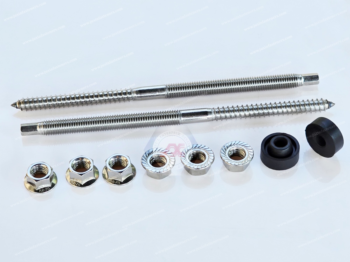
Manufacturing Consistency and Electrical Equipment Installation
Manufacturing and production teams often require repeatable installation procedures.
Dimensional Consistency
Stable dimensions support predictable assembly.
Thread Quality
Correct thread engagement is important for compatible nuts and fastening components.
Installation Tool Compatibility
Specified tools and procedures help control installation variation.
Product Identification
Clear marking and packaging can reduce part-mixing risks.
Batch Consistency
Controlled specifications support repeated project installations.
Inspection
Defined acceptance criteria help identify installation problems.
Change Control
Material, geometry, coating and expansion-component changes may require reassessment.
Information Gain: Standardized Anchor Schedules Improve EPC Installation Control
Large electrical projects may contain many repeated fixing points.
Grouping approved anchor configurations by equipment category, load requirements and substrate conditions can improve installation planning.
However, standardization must not override product-specific engineering requirements.
Procurement Requirements for Power Infrastructure Fasteners
Electrical infrastructure procurement may require detailed technical and commercial documentation.
Technical Requirements
Product drawing
Anchor type
Diameter and length
Thread designation
Material specification
Surface finish
Installation instructions
Required technical qualification
Quality Requirements
Dimensional inspection
Mechanical property verification
Coating requirements
Product identification
Batch traceability
Inspection records
Change control
Commercial Requirements
Sample quantity
Initial order quantity
Annual forecast
MOQ expectations
Packaging
Lead time
Delivery schedule
Repeat-order planning
Supplier Qualification Matrix
| Requirement | Procurement purpose |
|---|---|
| Product drawing | Verify dimensions |
| Anchor mechanism | Prevent incorrect substitution |
| Concrete qualification | Support engineering approval |
| Seismic requirements | Address project-specific demands |
| Material documentation | Verify specified properties |
| Coating specification | Address environmental exposure |
| Installation instructions | Support site consistency |
| Inspection criteria | Support quality control |
| Traceability | Support project records |
| Change control | Protect approved configurations |
Information Gain: EPC Procurement Should Separate Approved Anchor Systems from General Fastening Hardware
Electrical infrastructure projects often require both ordinary industrial fastening components and specially qualified anchoring systems.
Bolts, nuts, washers and sheet-metal fastening components may be procured according to their relevant specifications.
Structural or seismic-sensitive concrete anchors may require additional product-specific technical evaluations and engineering approval.
These procurement categories should not be treated as interchangeable.
OEM Customization and Drawing-Based Electrical Equipment Fasteners
Electrical equipment manufacturers may require:
Special fastener dimensions
Material requirements
Surface finishes
Metric or inch thread configurations
Nut and washer assemblies
Equipment-specific threaded components
Cabinet fastening hardware
Packaging and identification requirements
Technical feasibility must be confirmed for each request.
Important Limitation
Changing the geometry, material, coating or expansion mechanism of a qualified anchor may affect its evaluated performance.
A customized product must not automatically be represented as retaining an existing ETA, ICC-ES report or other technical approval.
Why Source Industrial Fasteners from Juxin Fasteners?
Juxin Fasteners has more than 20 years of experience in international industrial fastener supply.
Our fastening portfolio includes:
Expansion bolts
Concrete anchoring hardware
Structural fastening components
Bolts and screws
Nuts and washers
Rivet nuts
Welding nuts
Self-clinching fasteners
Custom threaded components
Drawing-based OEM fasteners
We welcome technical and commercial inquiries involving:
Product drawings
Dimensions and tolerances
Material requirements
Surface finishes
Electrical equipment applications
Inspection specifications
Packaging
Bulk procurement
Delivery planning
Specific product availability, customization feasibility, technical documentation, MOQ and lead times must be confirmed for each inquiry.
For seismic-sensitive or safety-critical electrical equipment anchoring, the required product qualification and engineering approval remain essential.
Frequently Asked Questions About Power Infrastructure Expansion Bolts
Can expansion bolts be used in substations?
Suitable mechanical anchors may be used for equipment supports, brackets and other connections where the concrete,
loading and installation conditions meet the project requirements.
Are expansion bolts suitable for transformers?
Certain auxiliary transformer supports may use suitable anchors.
Primary transformer anchorage requires separate engineering evaluation.
Can expansion bolts be used for electrical cabinets?
Yes, where the selected anchor and supporting concrete meet the equipment and project requirements.
Are expansion bolts suitable for cable trays?
Suitable mechanical anchors may be used for cable support brackets when the loading, substrate and installation requirements are satisfied.
Can expansion bolts be used outdoors?
Yes, where the material and corrosion-protection configuration are appropriate for the environment.
Are galvanized expansion bolts suitable for substations?
Certain qualified galvanized systems may be suitable for specified outdoor environments.
Can expansion bolts be used in cracked concrete?
Some mechanical anchors are qualified for cracked concrete. Others are not.
Are expansion bolts suitable for seismic applications?
Some products have specific seismic qualifications.
Suitability must be verified for the actual equipment installation.
Does IEEE 693 certify expansion bolts?
IEEE 693 addresses substation equipment seismic design and qualification.
It does not automatically qualify an individual expansion bolt.
Can an expansion bolt provide electrical grounding?
A conventional concrete expansion anchor should not automatically be treated as an approved grounding or bonding connection.
What is effective embedment?
Effective embedment is a product-specific parameter used in anchoring design.
What installation torque should be used?
Use the specified setting procedure and torque for the exact anchor product.
Can a different expansion bolt replace an approved product?
Only after the required engineering and technical documentation review.
Can Juxin Fasteners review OEM electrical equipment fastening requirements?
Yes. Drawing-based industrial fastening inquiries can be reviewed for technical and commercial feasibility.
Power Infrastructure Expansion Bolt RFQ Checklist
For efficient technical review and quotation, provide the following information where available.
Product Information
Anchor type
Existing product reference
Technical drawing
Nominal diameter
Overall length
Thread designation
Material
Surface finish
Nut and washer configuration
Application Information
Power facility type
Equipment description
Installation orientation
Environmental exposure
Expected service conditions
Maintenance requirements
Concrete Information
Concrete strength
Cracked or uncracked condition
Concrete member thickness
Edge distance
Anchor spacing
Reinforcement constraints
Existing or new construction
Engineering Requirements
Tensile load
Shear load
Combined loading
Dynamic or seismic requirements
Effective embedment
Required technical qualification
Applicable engineering standard
Installation Requirements
Drill diameter
Hole depth
Hole preparation
Setting procedure
Installation tools
Inspection requirements
Commercial Requirements
Sample quantity
Initial order quantity
Annual forecast
MOQ expectations
Packaging
Required lead time
Delivery destination
Request Expansion Bolts and OEM Fastening Solutions for Power Infrastructure
Juxin Fasteners welcomes inquiries from power equipment manufacturers, substation contractors, electrical equipment OEMs,
renewable energy suppliers, EPC engineering companies, structural engineers, mechanical engineers, manufacturing engineers, production managers,
supplier development teams and international procurement professionals.
Whether your project requires expansion bolts, concrete anchoring hardware, structural fastening components,
cabinet hardware or drawing-specific OEM fasteners, reliable selection begins with understanding the equipment, substrate, loading conditions and environmental requirements.
Send us your drawings, product specifications, material requirements, surface treatment details, quantities and delivery requirements for technical and commercial review.
For seismic-sensitive or safety-critical electrical infrastructure anchoring, include the required engineering and product qualification documentation.
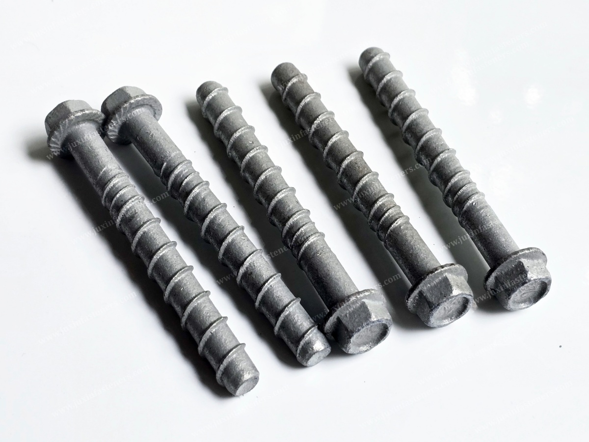
Company: Juxin Fasteners
Website: https://www.juxinfasteners.com/
Email: info@juxinfasteners.com
Reliable Power Infrastructure Fastening Requires Coordinated Mechanical Design, Appropriate Concrete Anchoring, Corrosion Protection, Verified Installation and Consistent Industrial Supply.
 MORE NEWS

Oct. 13, 2026
Contact Us
Tel.:
+86 020 8621 0320
+86 020 3121 6067
E-mail:
Technical Support:
Navigation
SEND INQUIREY