Call Us
+86 136 6007 9809
Call Us
+86 136 6007 9809

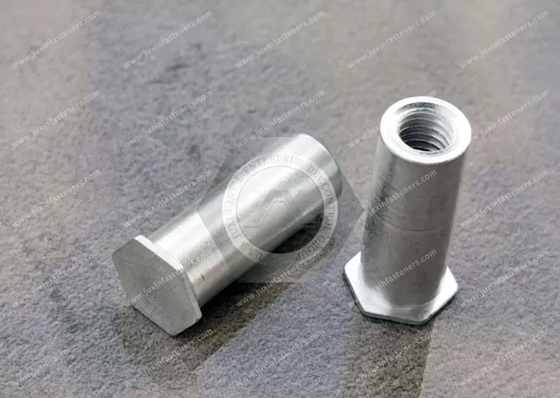
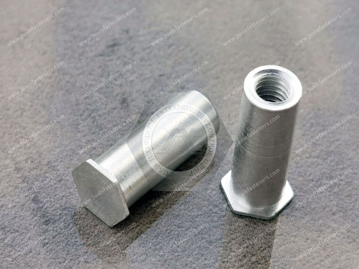
JUXIN FASTENERS supplies JX-BSOA aluminum blind threaded self-clinching standoffs for lightweight sheet-metal assemblies, electronic enclosures and PCB mounting. These standoffs provide permanent internal threaded mounting points and defined component spacing without a through-thread opening in the standoff body. The blind-hole design limits screw penetration and can maintain a flush, closed exterior panel face when correctly installed.
Product Series: JX-BSOA
Material: Aluminum
Exact Alloy and Temper: According to approved drawing
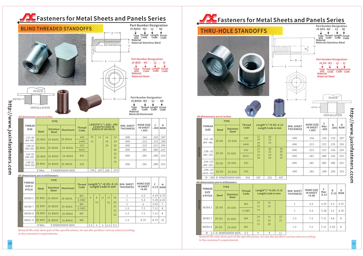
Metric Threads: M3, M4, M5, M6
Inch Threads: Selected #4–#10 sizes
Thread Configuration: Blind-Hole Internal Female Thread
Standoff Height: According to approved drawing
Usable Thread Depth: According to approved drawing
Installation: Controlled Parallel Pressing Force
Parent-Sheet Compatibility: Subject to material, hardness and thickness verification
Custom Dimensions: Subject to technical review
Product Specification
Product Specifications — Aluminum Blind Threaded Self-Clinching Standoffs, JX-BSOA Series
JUXIN FASTENERS supplies JX-BSOA aluminum blind threaded self-clinching standoffs for OEM manufacturers requiring lightweight, permanently retained threaded spacers in sheet-metal assemblies.
These aluminum clinch standoffs provide defined spacing between a mounting panel and an attached component while retaining an internal female thread.
The blind-hole thread terminates within the standoff body, preventing the mating screw from passing completely through the fastener.
When the correct standoff is installed in a compatible sheet using approved tooling, the assembly can provide a flush and closed exterior panel surface.
The JX-BSOA series is intended for engineering evaluation in electronic enclosures, PCB mounting systems, telecommunications equipment, control panels, precision instruments and other lightweight fabricated assemblies.
Product Technical Overview
Product Name: Aluminum Blind Threaded Self-Clinching Standoffs
Alternative Names: Aluminum Blind-Hole Clinch Standoffs, Aluminum Closed-End Threaded Standoffs, Aluminum Press-In Threaded Spacers
JUXIN Series: JX-BSOA
Material: Aluminum
Exact Alloy: According to approved drawing
Material Temper: According to approved drawing
Thread Configuration: Blind-Hole Internal Female Thread
Metric Thread Sizes: M3, M4, M5, M6
Inch Thread Family: Selected #4–#10 sizes
Individual Thread Pitches: According to approved part number
Standoff Height: According to approved drawing
Usable Blind-Hole Thread Depth: According to approved drawing
Mounting-Hole Diameter: According to approved installation data
Minimum Sheet Thickness: According to selected part specification
Parent-Sheet Material: Compatible sheet metal, subject to verification
Installation Method: Controlled Parallel Pressing Force
Attachment Principle: Mechanical Self-Clinching
Installed Profile: Flush and closed on the designated exterior panel face when correctly specified and installed
Push-Out Resistance: Subject to part-specific verification
Torque-Out Resistance: Subject to part-specific verification
Surface Finish: According to approved specification
Custom Configurations: Subject to technical and manufacturing review
What Is an Aluminum Blind Threaded Self-Clinching Standoff?
An aluminum blind threaded self-clinching standoff is a lightweight metal spacer with an internal female thread that terminates within the fastener body.
The standoff is installed into a properly prepared mounting hole in compatible sheet metal.
During installation, controlled pressing force causes the surrounding sheet material to flow into the fastener's retaining features.
The resulting mechanical interlock secures the standoff to the panel.
A mating screw can then be installed into the internal thread to secure a circuit board, bracket, electronic module or other component at a defined distance from the mounting panel.
Why Select Aluminum Blind Threaded Standoffs?
Aluminum may offer advantages in applications where mass reduction is important.
Potential engineering benefits include:
Lower fastener mass than comparable steel designs
Permanent threaded mounting points
Defined component spacing
Reduced loose-part handling
No through-thread opening in the standoff body
Controlled mating screw penetration
Compatibility with suitable lightweight sheet-metal assemblies
Flexibility in component mounting locations
The final choice must account for the actual aluminum alloy, mechanical properties and service requirements.
Engineering Information Gain — Lightweight Does Not Automatically Mean Better
Aluminum is less dense than steel, but material density is only one design consideration.
A lighter standoff may be beneficial in equipment containing many mounting points.
However, the selected aluminum alloy may have lower mechanical strength, hardness or thread-wear resistance than a particular steel alternative.
The engineering decision should consider:
Fastener mass
Required thread strength
Repeated assembly cycles
Parent-sheet hardness
Push-out resistance
Torque-out resistance
Component loads
Corrosion environment
Cost
Aluminum is an engineering option, not a universal replacement for steel or stainless steel.
JX-BSOA vs. JX-BSO vs. JX-BSOS
JX-BSOA
Material: Aluminum
Primary Differentiator: Lightweight blind threaded spacing
JX-BSO
Material: Steel
Primary Differentiator: Steel blind threaded spacing
JX-BSOS
Material: Stainless Steel
Primary Differentiator: Stainless steel blind threaded spacing
All three families provide blind threaded standoff functions.
However, identical nominal thread sizes do not establish mechanical or installation interchangeability.
Differences in material, hardness, installation geometry and performance must be reviewed.
Blind Threaded vs. Thru-Hole Threaded Standoffs
Blind Threaded Standoffs
The internal thread terminates inside the standoff.
A mating screw cannot pass completely through the body.
Thru-Hole Threaded Standoffs
The internal opening extends through the standoff.
A mating screw may project through the body if the assembly provides sufficient clearance.
Blind threaded designs may be selected where screw penetration must be limited or a closed exterior face is required.
Thru-hole designs may be selected where through-thread access is necessary.
Engineering Information Gain — Blind Thread Is Not Blind Installation
A blind threaded standoff has a closed-end internal thread.
This does not mean it can automatically be installed without access to the opposite side of the mounting panel.
Self-clinching standoffs generally require suitable press tooling and panel support.
Where only one-sided installation access is available, an appropriate blind-installed fastener may be a better alternative.
This distinction prevents confusion between blind threaded clinch standoffs and blind rivet nuts.
Metric Thread Sizes
The supplied metric thread family includes:
M3
M4
M5
M6
Actual availability depends on the approved JX-BSOA part number.
ISO 261 provides relevant metric thread combinations.
ISO 965 provides relevant metric thread tolerance requirements.
Inch Thread Sizes
The supplied inch-thread family includes selected #4–#10 sizes.
Exact Unified thread designations and pitches must be confirmed for each part.
ASME B1.1 provides relevant Unified inch screw thread requirements.
Metric and Unified inch threads are not interchangeable.
Metric and Inch Thread Selection
OEM programs may require either metric or Unified inch threaded standoffs.
The correct selection depends on the mating screw, engineering drawing and target market.
A metric thread designation should not be converted into an inch thread designation and treated as interchangeable.
For example, an M4 thread and a #8 Unified thread require different mating fasteners.
Aluminum Alloy Selection
The supplied product information identifies aluminum but does not establish a specific alloy or temper.
These details must be confirmed before production.
Selection factors include:
Yield strength
Hardness
Ductility
Machinability
Corrosion resistance
Thread performance
Clinching behavior
Surface finish requirements
No specific aluminum alloy or temper is claimed without supporting documentation.
Engineering Information Gain — Aluminum Fastener Hardness vs. Aluminum Panel Hardness
Self-clinching installation depends on controlled deformation of the parent-sheet material.
The parent sheet must be sufficiently compatible with the fastener's clinching geometry and mechanical properties.
A hard aluminum panel may not deform adequately around a selected aluminum fastener.
A soft aluminum panel may deform more readily but may have limited installed load capacity.
The correct selection requires verification of:
Fastener alloy and temper
Fastener hardness
Parent-sheet alloy and temper
Parent-sheet hardness
Sheet thickness
Mounting-hole dimensions
Installation force
Required retention performance
Do not assume that every aluminum clinch standoff can be installed into every aluminum sheet.
Blind-Hole Thread Depth
The internal thread terminates within the standoff body.
The usable blind-hole thread depth determines how far the mating screw can enter.
The engineer must account for:
Required thread engagement
Screw length
Attached component thickness
Washer thickness
Bottom clearance
Manufacturing tolerances
The usable thread depth must be obtained from the approved drawing.
Engineering Information Gain — Screw Bottoming Risk
A screw that is too long may contact the bottom of the blind hole before the attached component is properly clamped.
This can create misleading tightening resistance.
Possible consequences include:
Incomplete clamping
Thread damage
Standoff damage
Distortion of lightweight panels
Assembly rework
Inconsistent production quality
Blind-hole depth and screw length must be reviewed together.
Screw Length Selection
A suitable screw length depends on the full assembly stack.
Important dimensions include:
Attached component thickness
Washer thickness, if used
Required thread engagement
Usable blind-hole depth
Required bottom clearance
Component tolerance
Screw-length tolerance
The final design must provide adequate thread engagement without unintended bottoming.
Engineering Example — M3 Aluminum Standoff for PCB Mounting
An OEM uses an M3 aluminum blind threaded standoff to support a circuit board inside a lightweight electronic enclosure.
The engineering team must establish:
Required board spacing
Board thickness
Mounting-hole position
Standoff height
Usable M3 thread depth
Screw length
Bottom clearance
Parent-sheet alloy
Parent-sheet hardness
Panel thickness
Installation tooling
Required mechanical retention
The selection should be validated using the approved product drawing and representative assembly.
Flush and Closed Exterior Panel Surface
Blind threaded self-clinching standoffs can provide a flush, closed exterior mounting face when installed according to the correct product geometry and installation requirements.
This can be useful in electronic enclosures where exterior screw projection is undesirable.
The actual installed profile must be verified.
Engineering Information Gain — Closed Exterior Face vs. Environmental Sealing
A blind threaded standoff has no through-thread opening in its body.
However, a closed standoff does not automatically create a waterproof or airtight enclosure.
Environmental sealing depends on the complete assembly, including panel interfaces, joints and other openings.
Any required ingress protection or sealing performance must be validated separately.
Standoff Height Selection
The standoff height establishes the distance between the mounting panel and the supported component.
Selection factors include:
PCB component clearance
Connector clearance
Airflow
Electrical clearance
Component alignment
Mechanical support
Service access
Assembly tolerance
The required height and tolerance should be specified on the engineering drawing.
Self-Clinching Installation Principle
JX-BSOA standoffs are installed using a controlled mechanical pressing process.
The standoff is positioned in a properly sized mounting hole.
Parallel squeezing force is applied using suitable tooling.
The parent-sheet material flows into the fastener's retaining geometry.
This creates a mechanical interlock between the standoff and the panel.
Installation Procedure
A typical installation sequence includes:
Confirm the JX-BSOA part number.
Verify the fastener alloy and temper.
Verify the parent-sheet material and hardness.
Confirm sheet thickness.
Prepare the specified mounting hole.
Inspect hole diameter and edge condition.
Position the standoff correctly.
Support the panel with suitable tooling.
Apply controlled parallel pressing force.
Complete the clinching operation.
Inspect seating and alignment.
Verify retention where required.
Installation force and tooling geometry must follow the approved part specification.
Mounting-Hole Requirements
Mounting-hole quality affects installed performance.
Important characteristics include:
Hole diameter
Hole tolerance
Roundness
Burr condition
Edge quality
Hole location
Sheet thickness
Parent-sheet hardness
The approved installation drawing should define the required hole geometry.
Minimum Sheet Thickness
Minimum compatible sheet thickness depends on the selected standoff design.
It cannot be determined from thread size alone.
A sheet that is too thin may not provide enough material to form the required mechanical interlock.
The approved minimum sheet thickness must be verified.
Minimum Edge Distance
The mounting hole must be positioned sufficiently far from panel edges and other features.
Insufficient edge distance can affect:
Local material flow
Panel deformation
Retention
Structural integrity
Installation consistency
The approved minimum edge distance should be followed.
Installation Force and Tooling
Suitable press equipment should apply controlled parallel force.
Important factors include:
Press alignment
Punch geometry
Anvil geometry
Panel support
Fastener orientation
Installation force
Final seating
Uncontrolled impact installation should not replace the approved clinching process.
Push-Out Resistance
Push-out resistance describes the installed standoff's resistance to axial displacement under defined test conditions.
Performance depends on:
Fastener geometry
Fastener material
Parent-sheet material
Sheet thickness
Mounting-hole dimensions
Installation quality
No universal push-out value is claimed.
Torque-Out Resistance
Torque-out resistance describes the installed standoff's resistance to rotation within the mounting sheet.
This is relevant when tightening or removing mating screws.
The required performance must be evaluated for the selected fastener and representative panel.
Engineering Information Gain — Thread Wear During Repeated Maintenance
Electronic equipment may require repeated removal and reinstallation of mounted components.
Aluminum internal threads can be susceptible to wear or damage depending on the alloy, screw material, engagement length and installation conditions.
For serviceable assemblies, evaluate:
Expected assembly cycles
Mating screw material
Thread engagement
Tightening torque
Cross-threading risk
Thread lubrication or coating requirements
Where repeated service demands exceed the selected aluminum design's capability, an alternative material may be appropriate.
Engineering Information Gain — Height and Bending Moment
A standoff supports a component at a distance from the mounting panel.
Lateral loads acting on the component can generate bending moments at the mounting interface.
Important factors include:
Standoff height
Component mass
Lateral acceleration
Vibration
Panel stiffness
Fastener retention
Joint geometry
A taller standoff can experience greater bending demand under the same lateral force.
Axial push-out and torque-out data alone may not represent every service condition.
Engineering Information Gain — Galvanic Corrosion
Aluminum standoffs may be assembled with steel or stainless steel mating components.
Where dissimilar metals are electrically connected in the presence of a conductive electrolyte, galvanic corrosion may occur.
The actual risk depends on:
Material combination
Surface area ratio
Moisture exposure
Coatings
Electrical continuity
Service environment
The complete assembly should be evaluated where corrosion is a concern.
Electrical Conductivity and PCB Mounting
Aluminum is electrically conductive.
An aluminum standoff should not be treated as an electrical insulator.
For PCB applications, the design must provide suitable electrical clearance or insulation where required.
Potential measures may include appropriate board layout, insulating components or other approved assembly features.
Thermal Considerations
Aluminum has useful thermal conductivity, but a standoff should not automatically be treated as a qualified thermal management component.
Heat transfer depends on:
Alloy
Contact geometry
Surface finish
Contact pressure
Assembly temperature
Surrounding components
Any thermal performance requirement should be evaluated at assembly level.
Electronic Enclosure Applications
Potential applications include:
Lightweight equipment housings
Electronic module supports
Controller enclosures
Instrument panels
Internal mounting structures
Fabricated aluminum housings
Blind threaded designs may be useful where exterior screw penetration is undesirable.
PCB Mounting Applications
Potential applications include:
Printed circuit board mounting
Controller board support
Electronic module spacing
Instrument circuit assemblies
Communication equipment boards
The design must provide the required mechanical spacing and electrical clearance.
Telecommunications Equipment
Potential applications include:
Network equipment enclosures
Communication modules
Electronic chassis
Internal support panels
Lightweight equipment housings
The complete assembly should be evaluated for vibration, service loads and environmental exposure.
Robotics and Automation
Potential applications include suitable:
Lightweight controller housings
Sensor mounting assemblies
Electronics support panels
Automated equipment modules
Mass reduction may be valuable, but required mechanical performance must be verified.
Industrial Control Equipment
Potential applications include:
Control panel electronics
Instrument modules
Equipment housings
Serviceable electronic assemblies
Internal mounting structures
Standoff dimensions and installation requirements should be defined in the OEM drawing.
Transportation Electronics
Potential applications include selected lightweight electronic equipment assemblies.
Where vibration, fatigue, shock or corrosion requirements apply, the complete fastening system must be validated.
No transportation-industry qualification is implied.
Aluminum Blind Standoffs vs. Loose Spacers
Loose spacers may require separate handling during assembly.
Self-clinching standoffs remain attached to the mounting sheet.
Potential manufacturing benefits include:
Reduced loose-part handling
Repeatable mounting locations
Defined spacing
Simplified assembly
Fewer positioning operations
The total installed cost should be compared for the intended production volume.
Aluminum Blind Standoffs vs. Welded Standoffs
Welded standoffs require a suitable welding process.
Self-clinching standoffs use mechanical pressing.
Relevant comparison factors include:
Parent-sheet alloy
Sheet thickness
Installation access
Heat effects
Surface finish
Mechanical performance
Equipment cost
Production volume
Neither technology is universally superior.
Aluminum Blind Standoffs vs. Blind Rivet Nuts
Blind rivet nuts are intended for installation from one side of the workpiece.
Self-clinching standoffs generally require suitable pressing equipment and panel support.
A blind threaded standoff provides both a spacing function and an internal thread.
A blind rivet nut primarily provides a retained internal thread.
The correct selection depends on assembly access and design requirements.
Alternative Attachment Technologies
Other attachment technologies may include:
Thru-hole self-clinching standoffs
Blind rivet nuts
Welded standoffs
Loose threaded spacers
Broaching standoffs
Surface-mount standoffs for compatible PCB assemblies
These technologies differ in installation method, mounting substrate and service performance.
They should not be treated as direct substitutes without engineering review.
Engineering Information Gain — Integrated Enclosure Supports vs. Separate Standoffs
Some electronic enclosures use formed bosses or integrated mounting features.
These may reduce separate part count in high-volume designs.
However, integrated features can limit mounting-location flexibility.
Separate self-clinching standoffs may be useful when:
Multiple product variants share a common enclosure
PCB layouts change between revisions
Mounting positions require customization
Tooling changes would be costly
Assembly flexibility is important
The correct solution depends on production volume, enclosure manufacturing method and lifecycle requirements.
OEM Procurement Information Gain — Total Installed Cost
The fastener unit price is only one component of the complete assembly cost.
Relevant factors include:
Fastener cost
Hole preparation
Press equipment
Tooling
Installation cycle time
Inspection
Scrap
Rework
Qualification
Packaging
Delivery reliability
For repeat-production OEM programs, dimensional consistency and installation reliability may be more valuable than a small difference in component price.
Supplier Interchangeability
Two aluminum blind threaded standoffs may share the same nominal thread and height but differ in:
Aluminum alloy
Temper
Fastener hardness
Blind-hole depth
Mounting-hole requirements
Retaining geometry
Installation force
Minimum sheet thickness
Push-out resistance
Torque-out resistance
Interchangeability must be evaluated against the approved engineering drawing and performance requirements.
OEM Supplier Qualification Checklist
Product Identity
Confirm JX-BSOA designation.
Thread
Verify metric or Unified inch thread size and tolerance.
Standoff Height
Confirm required spacing dimension and tolerance.
Blind-Hole Depth
Confirm usable thread depth and bottom clearance.
Material
Confirm aluminum alloy and temper.
Parent Sheet
Confirm alloy, temper, hardness and thickness.
Mounting Hole
Verify diameter, tolerance and edge condition.
Installation
Confirm tooling, orientation and pressing requirements.
Performance
Define push-out, torque-out and relevant service-load acceptance criteria.
Documentation
Specify inspection records, traceability and drawing revision requirements.
Commercial Requirements
Confirm order quantities, annual demand, packaging and delivery expectations.
Relevant Engineering Standards
ISO 261 — ISO metric screw thread combinations.
ISO 965 — ISO metric screw thread tolerances.
ASME B1.1 — Unified inch screw threads.
ISO 6508-1 — Rockwell hardness testing.
ISO 6506-1 — Brinell hardness testing.
ASTM E18 — Rockwell hardness testing of metallic materials.
ASTM E10 — Brinell hardness testing of metallic materials.
ASTM B221 — Aluminum and aluminum-alloy extruded bars, rods, wire, profiles and tubes, where applicable to the selected raw material.
These standards are relevant engineering references and do not imply that every supplied product has been certified to them.
Frequently Asked Questions
What is an aluminum blind threaded self-clinching standoff?
It is a lightweight threaded spacer with a closed-end internal thread that is mechanically retained in compatible sheet metal.
What is the main advantage of aluminum standoffs?
Lower mass may be useful in lightweight equipment assemblies, subject to mechanical performance requirements.
Can aluminum blind threaded standoffs be installed in aluminum panels?
Suitable combinations may be evaluated, but compatibility depends on the actual alloy, temper, hardness, sheet thickness and clinching geometry.
What is the difference between blind threaded and thru-hole standoffs?
Blind threaded standoffs have limited internal thread depth. Thru-hole standoffs have an opening through the body.
Are aluminum blind threaded standoffs electrically insulating?
No. Aluminum is electrically conductive.
Can aluminum blind threaded standoffs be used for PCB mounting?
Yes, suitable designs may be evaluated for supporting circuit boards at a defined height.
What happens if the mating screw is too long?
The screw may bottom in the blind hole before the attached component is properly clamped.
Are blind threaded standoffs waterproof?
Not automatically. Any environmental sealing requirement must be evaluated at assembly level.
Can self-clinching standoffs be installed with a hammer?
Controlled press installation is recommended. Uncontrolled impact should not replace the approved installation process.
Can aluminum blind standoffs replace steel or stainless steel versions?
Only after dimensional, material, installation and mechanical performance compatibility has been verified.
Related Sheet-Metal Fastening Solutions
Related JUXIN FASTENERS product categories include:
Steel Blind Threaded Self-Clinching Standoffs — for steel blind threaded spacing applications.
Stainless Steel Blind Threaded Self-Clinching Standoffs — for stainless steel blind threaded spacing applications.
Aluminum Thru-Hole Self-Clinching Standoffs — for lightweight applications requiring an opening through the standoff body.
Steel Thru-Hole Self-Clinching Standoffs — for compatible steel spacing applications.
Stainless Steel Thru-Hole Self-Clinching Standoffs — for compatible stainless steel spacing applications.
Self-Clinching Nuts — for retained internal threads without an extended spacing body.
Self-Clinching Studs — for permanent external threaded mounting points.
Blind Rivet Nuts — for one-sided threaded installation.
These product names are contextual internal-link anchor texts. Add hyperlinks only to verified relevant live product pages.
OEM RFQ Checklist
For technical review and quotation, please provide:
Required JUXIN series
Engineering drawing or CAD file
Metric or Unified inch thread size
Thread tolerance
Required standoff height
Usable blind-hole thread depth
Mating screw specification
Required thread engagement
Bottom clearance
Aluminum alloy
Aluminum temper
Parent-sheet material
Parent-sheet hardness
Sheet thickness
Mounting-hole dimensions
Minimum edge distance
Installation orientation
Available press equipment
Installation force requirements
Push-out resistance requirements
Torque-out resistance requirements
Service-load requirements
Surface finish requirements
Inspection documentation
Initial order quantity
Estimated annual demand
Packaging requirements
Delivery schedule
JUXIN FASTENERS — OEM Aluminum Blind Threaded Standoff Supply
JUXIN FASTENERS supplies aluminum self-clinching standoffs and sheet-metal fastening products for international OEM engineers, purchasing managers, supplier development teams and equipment manufacturers.
The JX-BSOA series can be evaluated for lightweight blind threaded spacing applications in compatible sheet-metal assemblies.
Potential applications include electronic enclosures, PCB mounting systems, telecommunications equipment, industrial control panels and precision fabricated housings.
For accurate product selection, customers should provide their engineering drawing, required standoff height, thread size, blind-hole depth, aluminum alloy, parent-sheet properties and installed performance requirements.
Request an OEM Technical Quotation
Email: info@juxinfasteners.com
Website: www.juxinfasteners.com
Please include the required thread size, standoff height, blind-hole depth, drawing, initial order quantity and estimated annual demand.
JUXIN FASTENERS — Aluminum Blind Threaded Self-Clinching Standoff Solutions for Lightweight OEM Sheet-Metal Engineering and Global Procurement.
Product Packaging
Product Packaging — Aluminum Blind Threaded Self-Clinching Standoffs
JUXIN FASTENERS supplies JX-BSOA aluminum blind threaded self-clinching standoffs with protective packaging for industrial and OEM shipments.
Product Series: JX-BSOA
Material: Aluminum
Inner Packaging: Poly Foam
Outer Packaging: Cartons
Shipping Arrangement: Palletized Packaging
Available Carton Dimension References:
29 × 19 × 19.5 cm
23.5 × 17.5 × 8 cm
Supplied Pallet Dimension Reference:
215 × 100 × 90 cm
The appropriate carton size, packing quantity, gross weight and pallet arrangement depend on the confirmed standoff dimensions and order requirements.
Thread Protection: Packaging should protect internal threads against mechanical damage and contamination.
Blind-Hole Protection: Packaging should minimize contamination entering the blind threaded cavity.
Clinching Feature Protection: Retaining undercuts and clinching features should be protected from deformation before installation.
Surface Protection: Aluminum surfaces should be protected against handling damage, scratching and deformation where required.
Product Identification: Customer-specified labels may identify part number, thread size, standoff height, blind-hole depth, aluminum alloy, quantity, lot number and drawing revision.
Series Segregation: Different thread sizes, standoff heights and blind-hole depths should be clearly identified to reduce mixing risk.
OEM Packaging: Customer-specific packing quantities, carton arrangements, labels and pallet configurations are subject to order confirmation.
Final packaging details will be confirmed against the approved purchase order.
For OEM packaging requirements and quotations:
Email: info@juxinfasteners.com
Website: www.juxinfasteners.com
Product Pictures
Contact Us
Tel.:
+86 020 8621 0320
+86 020 3121 6067
E-mail:
Technical Support:
Navigation
SEND INQUIREY