Call Us
+86 136 6007 9809
Call Us
+86 136 6007 9809

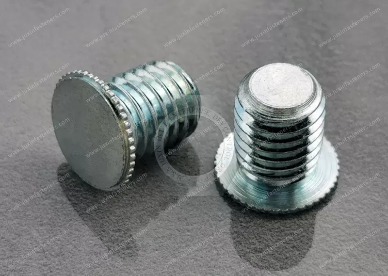
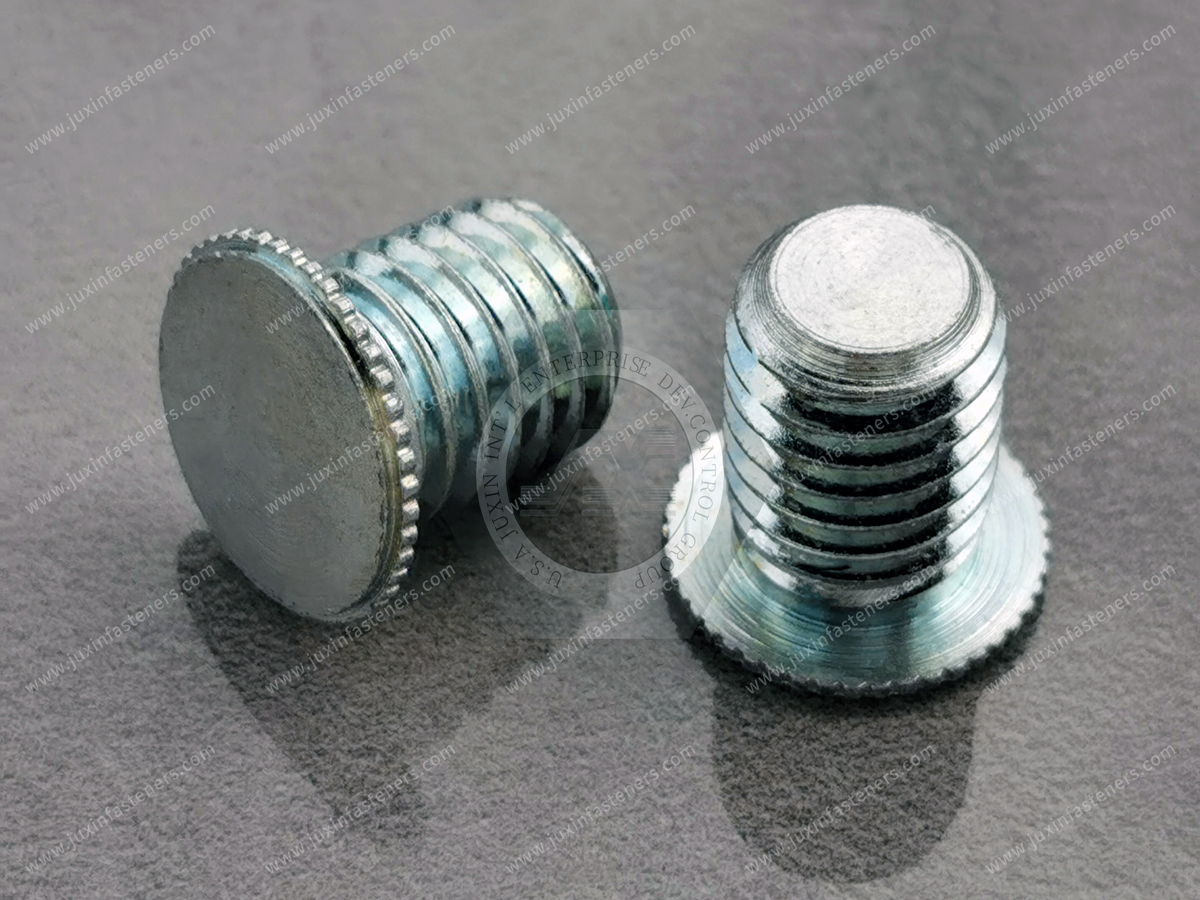
JUXIN FASTENERS supplies concealed-head self-clinching studs for metal panels requiring permanently retained external threads without a through-hole on the visible exterior surface. The stud head is pressed into a correctly machined blind recess, where displaced parent material engages its retention features.
These hidden-head threaded studs are suitable for engineering evaluation in electronics enclosures, precision equipment housings, control panels and other assemblies where appearance and surface continuity are important.
Product Series: JX-CFHA, JX-CFHC, JX-CHA, JX-CHC
Material Family: Steel
Installation: Press Clinching into a Machined Blind Hole
Thread Range: #4–#10 and metric sizes subject to drawing confirmation
Panel Thickness: Configuration-dependent; 0.062 in (approximately 1.57 mm) is a stated family reference
Custom Requirements: Subject to Drawing and Technical Review
Product Specification
Concealed-Head Self-Clinching Studs for Metal Panels – Engineering Design, Installation and OEM Sourcing
Product Overview
Concealed-head self-clinching studs provide externally threaded attachment points in metal panels while preserving the opposite, visible surface.
Unlike conventional through-panel clinch studs, these fasteners are installed into a specially prepared blind recess rather than a hole passing completely through the sheet.
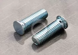
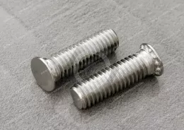
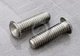
The stud head is mechanically retained inside the parent material. The externally threaded shank remains available on the installation side for attaching brackets, internal components and other equipment.
The concealed-head arrangement is especially useful where the exterior of a metal enclosure must remain free of visible fastener heads, mounting holes or protrusions.
JUXIN FASTENERS supplies concealed-head stud configurations identified as JX-CFHA, JX-CFHC, JX-CHA and JX-CHC for customer drawing review and OEM fastening projects.
Product Specifications
Product Category: Concealed-Head Self-Clinching Studs
Alternative Engineering Terms: Hidden-Head Clinch Studs, Blind-Hole Clinch Studs, Concealed Threaded Studs
Product Series: JX-CFHA, JX-CFHC, JX-CHA, JX-CHC
Fastener Function: Captive External Thread
Material Family: Steel
Example Material Background: C45, C46, C20 and Free-Machining Steels
Actual Material Grade: According to Approved Product Drawing
Head Style: Concealed Clinching Head
Installation Hole: Machined Blind Recess
Installation Method: Controlled Press Clinching
Installation Tooling: Suitable Punch and Supporting Anvil
Thread Designation: According to Selected Product Drawing
Thread Size References: #4–#10 and Metric Sizes Requiring Confirmation
Stud Length: According to Approved Drawing
Minimum Panel Thickness: Configuration-Specific
Family Thickness Reference: 0.062 in, Approximately 1.57 mm
Surface Finish: According to Approved Specification
Custom Dimensions: Subject to Technical Review
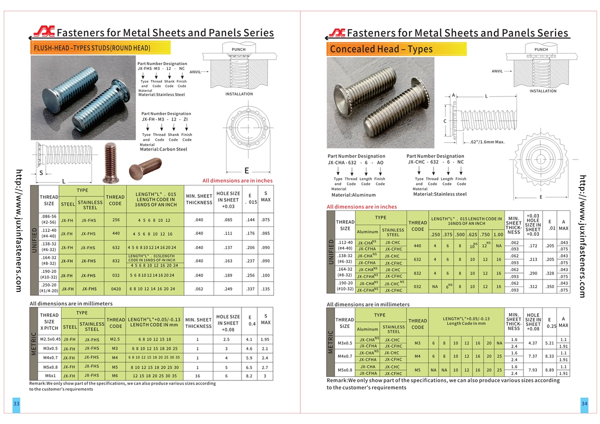
Detailed dimensions should be checked against the applicable technical drawings and CAD information. The supplied product reference identifies catalog pages 33–34.
What Is a Concealed-Head Self-Clinching Stud?
A concealed-head self-clinching stud is a mechanical fastener that creates a captive male-threaded attachment point without penetrating the opposite surface of the mounting panel.
Its specially designed head is inserted into a blind recess machined from the installation side.
During controlled pressing, parent-sheet material is displaced into the stud's retention features.
This mechanical engagement secures the head inside the panel.
The stud shank remains accessible for assembly, while the opposite surface is preserved.
The fastener therefore provides a combination of internal mounting functionality and a clean exterior appearance.
How Concealed-Head Clinching Works
The installation process begins with preparing a correctly sized blind recess.
The recess must provide the required head clearance, engagement geometry and remaining material thickness.
The stud head is positioned inside the prepared hole.
A suitable press applies force through the installation tooling.
The parent material flows around the head and into the designed retention features.
The resulting mechanical connection resists movement and rotation under applicable loads.
This process differs from conventional self-clinching studs installed through a complete panel hole.
The blind recess and remaining wall thickness are essential parts of the attachment design.
Engineering Information Gain – Why the Blind Hole Is Part of the Fastener System
The stud alone does not determine the success of a concealed-head connection.
The machined recess effectively becomes part of the fastening system.
Its diameter, depth, geometry and surface condition determine how much material is available for retention.
A recess that is too shallow may prevent proper head seating.
A recess that is too deep may leave insufficient material beneath the stud.
Incorrect diameter or geometry can reduce mechanical engagement.
For this reason, the mounting-hole drawing should be controlled with the same care as the stud drawing.
The fastener and its installation recess should be approved as a matched design.
The Advantage of an Uninterrupted Exterior Surface
The principal design advantage of concealed-head studs is that the opposite panel surface remains uninterrupted by the fastener installation.
This can be valuable in equipment where visible mounting holes or bolt heads would affect appearance.
It may also help avoid exterior recesses that collect dirt or interfere with adjacent components.
Applications include consumer electronics housings, precision instrument panels and equipment covers.
The concealed-head design does not automatically create a watertight or pressure-tight assembly.
Sealing and environmental protection must be evaluated separately.
Steel Material Selection
The supplied material background includes C45, C46, C20 and free-machining steel families.
These materials differ in carbon content, machinability, strength and heat-treatment response.
The actual grade used for a particular concealed-head stud configuration must be confirmed.
Material selection may influence the fastener's dimensional stability, retention-feature behavior and corrosion-protection requirements.
A grade suitable for one product configuration should not be assumed suitable for another.
The selected material should be identified in the approved drawing and purchase specification.
International Material References
Relevant material specifications may include EN 10083 series references for applicable engineering steels and ASTM or SAE material designations where a documented equivalent is established.
Material equivalence should not be assumed from similar names alone.
Chemical composition, mechanical properties and delivery condition must be checked.
No specific international material certification is claimed without supporting documentation.
Minimum Panel Thickness and Remaining Wall
Concealed-head installation requires sufficient panel thickness to accommodate the blind recess while preserving material beneath it.
The supplied product information references metal sheets as thin as 0.062 inch for certain configurations.
This is approximately 1.57 mm.
However, the value should not be applied universally to every thread size or product series.
The minimum acceptable thickness depends on the selected stud geometry, recess depth, parent material and required retention performance.
The engineer must confirm the applicable drawing before releasing the panel design.
Engineering Information Gain – Remaining Wall Thickness Is Not the Same as Nominal Sheet Thickness
Nominal panel thickness is only the starting point.
The relevant design condition is the amount of sound parent material remaining beneath the machined blind recess.
That remaining material may be reduced by sheet-thickness tolerance, machining-depth variation and surface finishing.
A panel nominally thick enough for the stud may become unsuitable if the recess is machined too deeply.
The engineering drawing should therefore control both the recess depth and the minimum remaining wall.
This is particularly important when machining thin metal covers.
Blind-Hole Machining Requirements
Concealed-head studs require a machined blind hole or recess compatible with the selected fastener.
A suitable center-cutting end mill may be used when appropriate for the specified geometry and material.
The hole should be produced with controlled diameter and depth.
Machining should avoid unwanted burrs, excessive taper and damage to the opposite surface.
The required dimensions must come from the selected product drawing.
The supplied information mentions center-cutting end mills, but availability of any particular cutting tool from JUXIN FASTENERS should be confirmed before quotation.
Hole Position and Edge Distance
A concealed-head stud requires enough surrounding material for mechanical retention.
The blind recess should not be placed too close to a panel edge, bend or other opening without engineering review.
Insufficient surrounding material may affect installation behavior or structural integrity.
Nearby formed features may also interfere with press tooling.
Edge-distance and spacing requirements should be determined from the applicable fastener drawing and assembly design.
Installation Equipment
The supplied installation concept uses a suitable punch and hollow supporting anvil.
The tooling must accommodate the projecting threaded shank and support the workpiece appropriately.
A controlled press applies the force required to seat the head and displace the parent material.
Tool alignment is important.
An unsuitable tool can damage the thread, distort the panel or produce incomplete clinching.
The exact tooling arrangement must be matched to the selected stud geometry.
Concealed-Head Stud Installation Procedure
Prepare the blind recess according to the approved drawing.
Remove chips and inspect the machined feature.
Position the stud head correctly inside the recess.
Support the workpiece with the specified tooling.
Apply controlled press force perpendicular to the mounting surface.
Continue until the required head seating condition is achieved.
Inspect the installed stud for alignment, seating and visible panel damage.
Where required, verify retention performance using representative assemblies.
Uncontrolled hammer installation should not be substituted for the approved press process.
Why Installation Force Must Be Verified
The installation force must be sufficient to create the required mechanical engagement.
Insufficient force may result in incomplete retention.
Excessive force can distort the panel or damage the fastener.
The required force depends on the stud geometry, material and recess dimensions.
The supplied information does not establish a universal installation force.
OEM production should use a qualified installation process with defined acceptance criteria.
Torque-Out Resistance
Torque-out resistance describes the installed stud's ability to resist rotation in the parent material.
It matters when a mating nut is tightened or removed.
Retention-feature geometry and the surrounding displaced material contribute to rotational resistance.
The actual performance depends on the fastener, blind recess, material and installation conditions.
No numerical torque-out rating is claimed without verified configuration-specific test data.
Pushout and Axial Retention
Axial retention describes resistance to displacement of the stud under loading.
Concealed-head stud performance depends on the mechanical engagement formed during pressing.
The load direction and installed geometry should be considered when defining a test.
Where axial retention is critical, representative qualification testing should be specified.
A general claim of substantial load capacity should not replace a defined engineering acceptance requirement.
Engineering Information Gain – The Cosmetic Surface Can Become the Structural Limit
A concealed-head stud is often selected because the exterior panel surface must remain untouched.
However, preserving that surface reduces the available depth for the fastener head and its retention features.
This creates a direct design trade-off.
A deeper recess may improve accommodation of the fastener head but reduce remaining wall thickness.
A shallower recess may preserve more material but limit installation geometry.
The designer must balance appearance, panel thickness, retention performance and manufacturing tolerance.
This trade-off should be evaluated before selecting the stud size.
Thread Selection
Concealed-head studs provide external male threads for use with compatible nuts or internally threaded components.
The selected thread designation must be specified.
For ISO metric threads, ISO 261 and ISO 965 are relevant references.
For Unified inch threads, ASME B1.1 may apply.
The supplied information mentions #4–#10 thread sizes.
The metric range in the source is inconsistently written as M8 to M5, so the exact available metric sizes must be verified from the dimensional table.
Metric and Unified inch threads are not directly interchangeable.
Stud Length and Assembly Clearance
The projecting threaded length should be selected according to the assembly stack-up.
Engineers should consider bracket thickness, washers, spacers, mating-nut engagement and nearby components.
Excessive projection may interfere with internal equipment.
Insufficient length may prevent proper fastening.
The required length should be identified in the drawing.
The panel-side head geometry and stud projection should be reviewed together.
Applications in Consumer Electronics
Concealed-head studs are useful for metal housings where exterior appearance matters.
Examples include entertainment equipment, computer enclosures and electronic device covers.
The hidden mounting feature can allow internal brackets or components to be attached without exposing a fastener head on the outer surface.
The final design must still satisfy mechanical, electrical and environmental requirements.
Applications in Precision Instrumentation
Precision instruments may require clean exterior panels and compact internal mounting arrangements.
Concealed-head studs can provide captive threaded points for internal structures.
They may reduce the need for visible exterior fasteners.
However, machining access, dimensional tolerance and remaining wall thickness should be evaluated early in the design.
Applications in Industrial Control Enclosures
Control panels and industrial equipment housings may require internal threaded mounting points while preserving the visible exterior.
A concealed-head stud can be considered where sufficient panel thickness is available.
The design must account for enclosure loads, mounting access and production sequence.
Any required electrical bonding or enclosure protection must be separately validated.
Applications in Telecommunications Equipment
Network equipment and communications housings often combine appearance, compact packaging and internal mounting requirements.
Concealed-head studs may be suitable for selected brackets, supports and enclosure components.
The parent material, environmental exposure and load conditions must be reviewed.
The fastener should not be assumed suitable for every enclosure material.
Applications in Automotive Interior Components
Concealed threaded mounting points may be considered for suitable interior trim supports, decorative metal panels and equipment housings.
The design should address vibration, assembly access and service loading.
Any automotive-specific performance or approval requirements must be separately established.
No automotive qualification is implied by the product description.
Concealed-Head Studs vs. Flush-Head Studs
A conventional flush-head self-clinching stud is installed through a panel hole.
Its head is designed to sit level with the installation-side surface.
A concealed-head stud is installed into a blind recess and preserves the opposite surface.
The two designs serve different appearance and manufacturing requirements.
They should not be treated as directly interchangeable.
The concealed-head design requires additional attention to blind-hole machining and remaining panel thickness.
Concealed-Head Studs vs. Weld Studs
Weld studs can create permanent threaded attachment points without requiring the same blind-milled clinching recess.
However, welding introduces process considerations such as heat input, distortion, spatter and surface finish.
Concealed-head self-clinching studs use mechanical material displacement rather than a welded joint.
The appropriate choice depends on panel material, thickness, appearance, production volume and required strength.
A weld stud is not automatically inferior, and a concealed-head clinch stud is not automatically suitable for every thin panel.
Concealed-Head Studs vs. Blind Rivet Studs
Blind rivet studs use a deformable body to provide external threads in applications designed for blind installation.
Concealed-head clinch studs rely on mechanical engagement within a prepared blind recess.
Their installation tooling and retention mechanisms are different.
Blind rivet studs may be preferable where rear-side access is unavailable.
Concealed-head studs may be preferable where an uninterrupted opposite surface is essential and suitable machining and press access are available.
The selected technology should match the complete assembly requirements.
Concealed-Head Studs vs. Swaged Studs
Swaging generally secures a fastener by deforming part of the fastener or associated geometry.
Self-clinching relies on controlled displacement of the parent material into retention features.
The two attachment methods have different material and tooling requirements.
Neither should be selected solely from its external appearance.
Concealed-Head Studs and PCB Mounting
Threaded studs can support the mounting of internal electronics assemblies.
However, a metal stud is electrically conductive.
Where a circuit board requires separation from a metal housing, an appropriate spacer or insulating component may be necessary.
Electrical clearance, grounding and short-circuit prevention must be addressed by the complete assembly design.
A concealed-head stud alone does not provide electrical insulation.
Engineering Information Gain – Concealed Does Not Mean Sealed
A blind recess preserves the opposite surface because it does not intentionally penetrate the panel.
This can support designs seeking to avoid visible openings.
However, concealed-head installation does not automatically establish a waterproof, airtight or pressure-rated assembly.
Panel porosity, machining damage, corrosion and other enclosure features may affect sealing performance.
If sealing is required, the enclosure must be validated against the relevant customer requirements.
Design for Manufacturability
The concealed-head stud should be selected before finalizing panel machining.
The recess requires suitable tool access.
The press requires sufficient clearance for the stud and supporting tooling.
Adjacent flanges, bends and internal structures can restrict installation.
The production sequence should account for machining, deburring, press installation and subsequent finishing.
For repeat production, the recess and installation process should be controlled using approved drawings.
Engineering Information Gain – Compare the Total Cost of the Attachment
A concealed-head stud may cost more to install than a conventional through-hole stud because the panel requires a machined blind recess.
However, it may eliminate the need for a visible fastener head or separate exterior cosmetic cover.
The appropriate comparison is therefore not limited to fastener unit price.
Engineers and purchasing teams should consider machining time, tooling, assembly labor, finishing, inspection and the cost of alternative enclosure designs.
A concealed-head solution may offer value when exterior appearance is a critical requirement.
For applications without that requirement, a simpler attachment method may be more economical.
OEM Quality and Inspection
Incoming inspection should follow the approved stud drawing.
Relevant characteristics may include thread dimensions, head geometry, overall length and material specification.
The blind recess should be inspected for diameter, depth and location.
After installation, the assembly should be checked for head seating, stud alignment and opposite-surface damage.
Where required, torque-out and axial retention tests should be conducted using representative panel materials.
Acceptance limits must be agreed before production.
Common Installation Problems
Stud rotation may indicate insufficient engagement, incorrect recess dimensions or unsuitable material properties.
Poor axial retention may result from incomplete clinching or inadequate remaining wall thickness.
Exterior surface marking may indicate excessive recess depth, excessive installation force or insufficient support.
Thread damage may result from unsuitable tooling or misalignment.
Inconsistent results between production batches may be related to variation in panel thickness, material properties or machining quality.
The corrective action should be based on the actual failure mechanism.
Frequently Asked Questions
What is a concealed-head self-clinching stud?
It is an externally threaded captive fastener installed into a prepared blind recess, allowing the opposite panel surface to remain uninterrupted.
Does a concealed-head stud require a through-hole?
No. The defining installation feature is a blind recess rather than a complete through-hole.
Can it be installed in very thin sheet metal?
Only when the selected configuration provides sufficient panel thickness and remaining material for proper clinching.
Is 0.062 inch the minimum for every model?
No. The supplied information references this thickness for the family, but each configuration must be checked against its own drawing.
Can the stud be installed with a standard press?
A suitable press may be used with correctly designed punch and anvil tooling.
Can the stud be used in stainless steel panels?
Compatibility must be established from the specific stud design, parent material and hardness requirements.
Does the hidden head make the assembly waterproof?
No. Environmental sealing requires separate engineering validation.
Can the studs be made to custom drawings?
Customer-specific dimensions and requirements may be reviewed for manufacturing feasibility.
What information is needed for an RFQ?
The buyer should provide the stud drawing, thread, length, material, panel thickness, recess geometry, performance requirements and quantity.
Relevant International Engineering References
ISO 261 – ISO metric screw thread general plan.
ISO 965 – ISO metric screw thread tolerances.
ASME B1.1 – Unified inch screw threads where specified.
ISO 6508-1 – Rockwell hardness testing where relevant.
ASTM E18 – Rockwell hardness testing where relevant.
ISO 6506-1 – Brinell hardness testing where relevant.
ASTM E10 – Brinell hardness testing where relevant.
ISO 2768 – General tolerances where explicitly specified and applicable.
These references support specification development where relevant. They do not establish automatic compliance or certification for the supplied studs.
Related JUXIN FASTENERS Products
Steel Flush-Head Self-Clinching Studs – JX-FH: For compatible panels where a through-hole flush-head design is acceptable.
Stainless Steel Flush-Head Self-Clinching Studs – JX-FHS: For applications requiring the corresponding stainless steel stud configuration.
Self-Clinching Standoffs: For providing a defined spacing function between components.
Self-Clinching Nuts: For creating captive internal threads in suitable metal sheets.
Blind Rivet Studs: For applications requiring appropriate one-sided installation.
Blind Rivet Nuts: For creating internal threads through a blind installation process.
These related product names can be linked to verified JUXIN FASTENERS product or category pages.
OEM Sourcing and Supplier Qualification
For OEM procurement, the concealed-head stud should be evaluated together with the panel drawing and installation process.
A supplier qualification package should identify the approved stud geometry, material, thread specification and dimensional tolerances.
The buyer should also define the parent material, panel thickness and blind-recess dimensions.
If retention performance is critical, the required test method and acceptance criteria should be established.
A similar-looking stud should not be accepted as a direct replacement without reviewing the complete attachment geometry.
Changes to the head profile, recess depth or parent material may affect installation performance.
Request a Concealed-Head Stud Quotation
JUXIN FASTENERS supports engineering and purchasing inquiries for concealed-head self-clinching studs and related sheet-metal fastening solutions.
Please provide your drawing or CAD file, required thread, stud length, material specification, panel thickness and blind-hole details.
Include the initial order quantity, estimated annual demand and any applicable testing or inspection requirements.
For projects replacing an existing fastener, include the current part number and drawing revision so the proposed configuration can be evaluated.
Email: info@juxinfasteners.com
Website: www.juxinfasteners.com
JUXIN FASTENERS – Concealed-Head Self-Clinching Studs for OEM Sheet-Metal Assemblies.
Product Packaging
Product Packaging
JUXIN FASTENERS offers packaging arrangements for concealed-head self-clinching studs according to the confirmed product dimensions and order requirements.
Protective inner packing, outer cartons and palletized shipping can be arranged subject to the approved packaging specification.
Packing quantities, carton dimensions and pallet configurations are confirmed according to the actual stud size, shipment quantity and handling requirements.
Different stud series, thread sizes, lengths and drawing revisions should be identified separately to support OEM receiving and inventory control.
Customer-specific packing instructions, labeling and shipment requirements can be reviewed before order confirmation.
Email: info@juxinfasteners.com
Website: www.juxinfasteners.com
Product Pictures
Contact Us
Tel.:
+86 020 8621 0320
+86 020 3121 6067
E-mail:
Technical Support:
Navigation
SEND INQUIREY