Call Us
+86 136 6007 9809
Call Us
+86 136 6007 9809

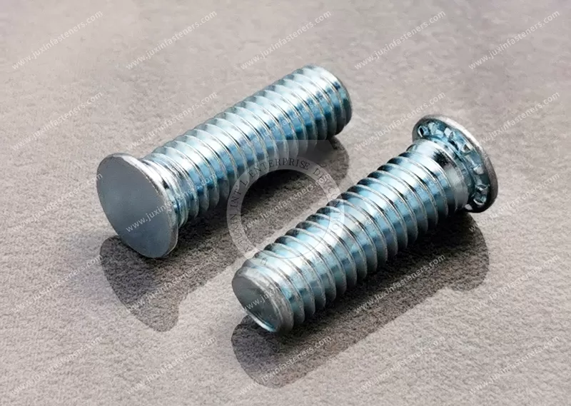
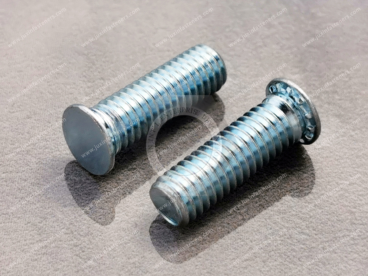
JUXIN FASTENERS supplies JX-FH steel flush-head self-clinching studs for thin sheet-metal assemblies requiring permanently retained external threads. These press-installed studs use a specially designed head and clinching features to secure the fastener within a properly prepared panel.
During installation, a controlled squeezing force displaces surrounding sheet material into the stud's retention features, creating a captive threaded mounting point with a flush head on the installation side.
Product Type: Flush-Head Self-Clinching Stud
Series: JX-FH
Material: Steel
Panel Compatibility: Suitable steel or aluminum sheets, subject to hardness and dimensional requirements
Installation: Controlled Press Clinching
Panel Hardness Guidance: HRB 80 maximum or HB 150 maximum, subject to product-specific verification
Thread and Length: According to Approved Drawing
Product Specification
Steel Flush-Head Self-Clinching Studs – JX-FH Engineering Specifications and OEM Sheet Metal Fastening Solutions
Product Overview
Steel flush-head self-clinching studs provide permanently retained external threads in compatible thin sheet-metal panels.
They are designed for applications where a conventional bolt would require access to both sides of the assembly or an additional operation to hold the fastener during tightening.
The JX-FH series uses a specially formed head with mechanical retention features. When the stud is pressed into a correctly sized mounting hole, the surrounding sheet material flows into these features, securing the stud against rotation and axial displacement.
The installed head is intended to sit flush with the appropriate panel surface, while the externally threaded shank projects from the opposite side for component attachment.
This arrangement is particularly useful for sheet-metal enclosures, electronics chassis, equipment housings and fabricated assemblies requiring captive mounting studs.
JUXIN FASTENERS supplies steel JX-FH flush-head self-clinching studs for OEM engineering and procurement projects.
Product Specifications
Product Name: Steel Flush-Head Self-Clinching Stud
Series: JX-FH
Fastener Type: Externally Threaded Self-Clinching Stud
Material: Steel
Head Design: Flush-Head Clinching Configuration
Attachment Technology: Mechanical Self-Clinching
Installation Method: Controlled Parallel Squeezing Force
Recommended Parent Materials: Compatible Steel or Aluminum Sheet
Panel Hardness Guidance: HRB 80 Maximum or HB 150 Maximum, Subject to Verification
Thread Size: According to Approved Product Drawing
Stud Length: According to Approved Product Drawing
Minimum Panel Thickness: According to Selected Stud Configuration
Surface Treatment: According to Confirmed Project Requirements
Custom Dimensions: Subject to Engineering Review
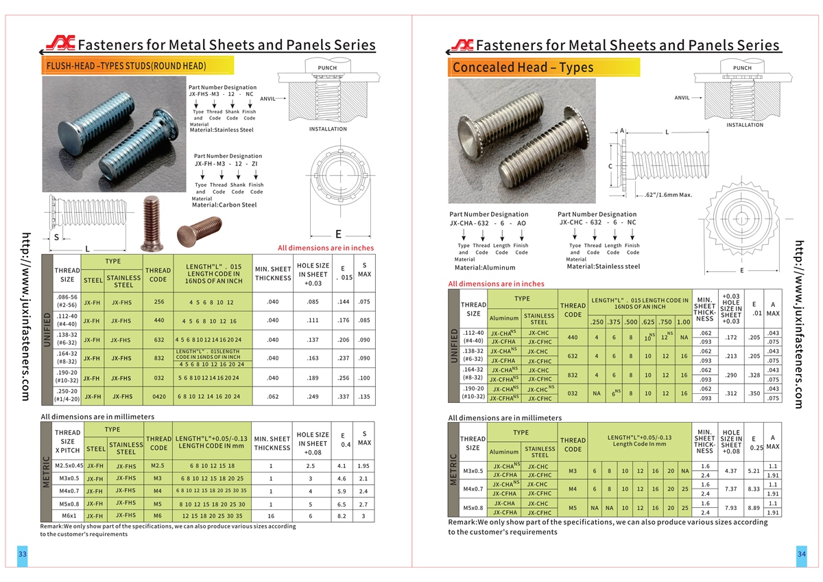
Product drawings and detailed dimensional tables should be consulted for the selected configuration. The supplied catalog reference identifies pages 33–34.
What Is a Flush-Head Self-Clinching Stud?
A flush-head self-clinching stud is a captive fastener that provides an externally threaded mounting point in a metal panel.
Unlike a conventional bolt, the stud does not need to be inserted and held during each subsequent assembly operation.
Once properly clinched into the panel, it remains attached to the parent sheet.
The projecting male thread can then receive a compatible nut or other internally threaded component.
The flush-head design helps maintain a substantially level surface on the installation side when the specified panel and fastener geometry are used.
This is valuable in applications where protruding bolt heads would interfere with adjacent components, enclosure clearances or assembly appearance.
How JX-FH Self-Clinching Studs Work
The installation process begins with a properly sized mounting hole in the parent sheet.
The stud is positioned in the hole with its head against the designated installation surface.
A suitable press applies a controlled squeezing force perpendicular to the panel.
As the stud head is pressed into the sheet, parent material is displaced into the designed retention features around the stud head.
These features typically include a groove and rotational engagement geometry.
The resulting mechanical interlock secures the stud to the panel.
The stud's externally threaded shank remains available for fastening additional components.
Correct installation requires appropriate panel thickness, hardness, hole dimensions, tooling alignment and press conditions.
Engineering Information Gain – Why Self-Clinching Depends on the Parent Sheet
Self-clinching is not simply a press fit based on friction.
The installation process depends on controlled plastic deformation of the parent sheet.
The sheet material must be capable of flowing into the stud's retention features without unacceptable cracking or distortion.
A panel that is too hard may not deform sufficiently.
A panel that is too thin may not provide enough material for proper mechanical engagement.
A mounting hole that is too large may reduce the material available for retention.
For this reason, the stud, panel and installation process must be treated as one engineered system.
Flush-Head Design and Panel Surface Requirements
The flush-head configuration is intended to avoid a protruding head on the designated installation side.
This can improve packaging efficiency in compact metal assemblies.
It may also simplify the installation of nearby components where a conventional bolt head would interfere.
However, flush installation depends on the specified panel thickness, stud geometry and correct press setup.
The term flush-head does not mean the entire stud is concealed within the sheet.
The externally threaded shank remains exposed on the opposite side.
Engineers should distinguish between the flush installation surface and the projecting threaded side when preparing assembly drawings.
Recommended Panel Materials
The supplied JX-FH technical guidance identifies steel and aluminum sheet as recommended parent materials.
The stated hardness guidance is HRB 80 maximum or HB 150 maximum.
These are material-hardness screening values, not guarantees of installation performance.
The applicable limit must be checked against the selected stud drawing and actual parent-sheet material.
Panel hardness, thickness, ductility and surface condition should all be considered.
A suitable hardness reading alone does not establish that every sheet grade or panel condition will produce a satisfactory clinched connection.
Stainless steel panels should not automatically be treated as compatible with the standard steel JX-FH configuration.
For harder stainless steel sheets, a stud specifically designed and qualified for that parent material may be required.
Engineering Information Gain – Why Harder Is Not Always Better
In many structural applications, engineers associate higher hardness with greater strength.
Self-clinching fasteners require a different evaluation.
The parent sheet must deform around the clinching features during installation.
If the parent material is too hard relative to the fastener and its clinching design, adequate material flow may not occur.
Increasing installation force does not necessarily solve this problem.
Excessive force may damage the stud, distort the panel or affect the threaded shank.
A compatible fastener and parent material combination is more important than simply selecting the hardest available components.
Minimum Sheet Thickness
The minimum acceptable sheet thickness depends on the particular JX-FH stud configuration.
A single universal minimum thickness should not be applied across all thread sizes and head geometries.
The correct minimum panel thickness must be obtained from the approved dimensional specification.
Where an enclosure uses multiple sheet gauges, each application should be checked independently.
A stud qualified for one sheet thickness may not provide the same retention in a thinner panel.
Panel thickness should also be considered after any manufacturing process that changes the local sheet geometry.
Mounting Hole Design
The mounting hole is a critical part of the self-clinching connection.
The hole diameter and tolerance must match the selected fastener specification.
Excessive clearance may reduce mechanical engagement and retention.
An undersized hole may interfere with insertion or cause unacceptable deformation during pressing.
The hole should be positioned to provide sufficient surrounding sheet material.
Edge distance, spacing between studs and proximity to bends or formed features should be reviewed.
The required dimensions must be established from the product drawing rather than estimated from the nominal thread diameter.
Hole Preparation and Manufacturing Quality
Mounting holes may be produced by punching, drilling or another suitable sheet-metal process.
The selected method must achieve the required dimensional accuracy and edge condition.
Burrs, local distortion and irregular hole geometry can interfere with proper seating.
A hole produced by punching may have different edge characteristics from one produced by drilling or laser cutting.
These differences should be considered when transferring a qualified assembly between manufacturing processes.
Where the product installation instructions specify a particular hole-entry direction or preparation method, those requirements should be followed.
Installation with a Press
JX-FH studs are intended for installation using a controlled squeezing operation.
A suitable press applies force through properly aligned tooling.
The stud should be supported so that the installation load does not damage the external thread.
The tooling must provide appropriate contact and clearance for the selected stud.
Installation should proceed until the required head position and mechanical engagement are achieved.
The exact press force depends on the stud configuration, parent material and tooling arrangement.
No universal installation-force value is claimed without product-specific data.
Hammering or uncontrolled impact should not replace the specified press installation process.
Engineering Information Gain – Press Force Is Not the Only Process Variable
A production line may experience inconsistent stud retention even when the same nominal press force is used.
Possible causes include differences in mounting-hole dimensions, parent-sheet hardness, tool alignment or the condition of the supporting surfaces.
Press stroke and final installed geometry can be important indicators of installation quality.
For repetitive OEM assembly, process control should consider the complete installation condition rather than relying on force alone.
Representative qualification samples can help establish acceptable installation parameters.
Torque-Out Resistance
Torque-out resistance describes the installed stud's ability to resist rotation within the parent sheet.
The mechanical engagement between the stud's retention features and displaced panel material provides rotational restraint.
Actual performance depends on stud geometry, parent material, hole dimensions and installation quality.
A high torque-out requirement should be stated explicitly in the engineering specification.
The stud's torque-out resistance should not be confused with the tightening torque applied to the mating nut.
The permissible assembly torque must be evaluated for the complete connection.
Pushout Resistance
Pushout resistance describes the installed stud's ability to resist axial displacement from the panel in the relevant loading direction.
The clinched head and retention features contribute to this resistance.
Pushout performance depends on the actual panel and installation configuration.
Where a mounting stud will be subjected to axial loading, representative testing should be considered.
No numerical pushout rating is assigned without verified product-specific data.
Engineering Information Gain – Torque-Out and Pushout Must Be Evaluated Separately
A stud can resist rotation while still having inadequate axial retention for a particular application.
Likewise, a stud with satisfactory pushout performance may not meet the rotational requirements of repeated assembly.
The two characteristics describe different failure modes.
For serviceable equipment, repeated removal and reinstallation of the mating nut can make rotational retention particularly important.
For brackets or mounted equipment subject to axial loads, pushout resistance may be a primary design consideration.
An effective OEM specification identifies both requirements where relevant.
Stud Thread Design
The externally threaded shank must match the intended mating nut or component.
For metric threads, ISO 261 and ISO 965 provide relevant references for thread designation and tolerance requirements.
For Unified inch threads, ASME B1.1 may be applicable when specified.
Metric and Unified inch threads are not directly interchangeable.
The nominal outside diameter of an M6 thread is approximately 0.236 inch, but this dimensional conversion does not establish compatibility with any UNC or UNF thread.
The final thread specification should identify the nominal size, pitch or series, tolerance and usable threaded length.
Stud Length and Assembly Stack-Up
The required stud length should be determined from the actual assembly.
Relevant dimensions include the thickness of the mounted component, washers or spacers, mating nut engagement and available clearance.
The projecting threaded length must be sufficient for the specified connection.
An unnecessarily long stud may interfere with adjacent components.
A stud that is too short may provide inadequate thread engagement.
The engineer should also consider manufacturing tolerances in the mounted components.
The correct length is therefore an assembly-design decision rather than simply a purchasing preference.
Engineering Information Gain – Retention and Joint Preload Are Different
The self-clinching connection secures the stud to the sheet.
The mating nut creates the clamping action between the attached components.
These are related but separate mechanical functions.
A properly installed stud can still be used in an inadequately designed bolted joint.
The designer must evaluate mating thread engagement, nut tightening, joint stiffness, service loads and any vibration-related loosening risk.
Self-clinching does not automatically provide a thread-locking function for the mating nut.
Steel Material Selection
The supplied material background identifies several possible steel families, including carbon steels and free-machining steels.
Different grades have different mechanical properties, manufacturing characteristics and heat-treatment responses.
The selected steel must be suitable for producing the clinching geometry and achieving the required installed performance.
No individual steel grade is represented as standard for all JX-FH configurations without confirmation.
Material substitutions should be reviewed against the approved drawing and installation requirements.
Surface Finish and Corrosion Protection
Steel studs may require corrosion protection according to the intended environment.
The finish should be specified separately from the base material.
For electroplated fastener coatings, ISO 4042 may be relevant.
The coating system, thickness and corrosion requirements should be confirmed for the project.
Where salt-spray testing is requested, ISO 9227 or ASTM B117 may be used as applicable test methods.
A salt-spray result should not be interpreted as a direct guarantee of service life.
For susceptible high-strength steel conditions, hydrogen embrittlement risk should be considered during coating-process selection.
No particular coating, corrosion rating or regulatory approval is claimed unless supported by the product documentation.
Engineering Information Gain – Coating Changes Can Affect Assembly
Changing a stud's surface finish may affect more than its appearance.
Coating thickness and surface characteristics can influence dimensions and contact conditions.
For a self-clinching fastener, the installation geometry must remain compatible with the parent sheet.
An OEM should therefore review coating changes when the clinching features or mounting-hole fit could be affected.
The finished fastener should be evaluated against the approved drawing.
Electrical Enclosures and Control Cabinets
Steel flush-head self-clinching studs can provide captive external mounting points in suitable electrical enclosure panels.
Applications may include equipment mounting, internal brackets and removable assemblies.
The flush installation side can be useful where external clearance or appearance is important.
Electrical bonding and grounding performance must be established separately where required.
A mechanically retained stud does not automatically guarantee electrical continuity.
Electronics Chassis and Computer Equipment
Electronics housings often require fixed threaded mounting points for brackets, covers and internal assemblies.
Flush-head clinch studs can reduce the need to handle loose bolts during production.
They may also support more repeatable component positioning.
For assemblies involving printed circuit boards, electrical clearance and insulation requirements must be reviewed independently.
A steel stud should not be assumed to provide electrical isolation.
Industrial Machinery and Automation
Industrial machinery housings may require captive threaded studs for guards, sensor brackets and auxiliary components.
The stud can simplify assembly where access to the back of the panel is restricted during final equipment assembly.
However, installation itself requires suitable access for the press and supporting tooling.
The assembly sequence should therefore be established before the enclosure is fully formed or populated.
Where vibration or dynamic loading is present, the complete bolted connection requires appropriate engineering validation.
Telecommunications Equipment
Telecommunications cabinets and network equipment enclosures may use press-installed studs to support internal brackets and equipment modules.
Flush-head configurations can be useful where compact panel arrangements leave limited clearance.
For outdoor installations, corrosion protection and environmental exposure should be reviewed.
The suitability of a particular finish depends on the service environment and project specification.
HVAC and Building Equipment
HVAC control compartments, metal housings and fabricated mounting panels may use captive threaded studs for component attachment.
The press-installed design can reduce loose fastener handling during assembly.
The selected stud must be compatible with the panel material and thickness.
Where equipment requires frequent maintenance, repeated assembly conditions should be included in the design review.
Transportation and Vehicle Equipment
Flush-head clinch studs may be considered for compatible noncritical panels and enclosure components in transportation equipment.
The design should account for vibration, corrosion exposure and service loads.
Safety-critical applications require the appropriate engineering validation and customer approval.
No transportation-specific qualification is implied without supporting evidence.
Self-Clinching Studs vs. Weld Studs
Self-clinching studs use mechanical installation and parent-sheet material flow.
Weld studs are attached through a welding process.
Self-clinching may be attractive where avoiding a welding operation is important and the sheet material is compatible.
Weld studs may be appropriate for other materials, thicknesses and structural requirements.
Neither technology should be considered universally superior.
The selection depends on panel material, load requirements, installation access and manufacturing process.
Self-Clinching Studs vs. Conventional Bolts
A conventional bolt is generally a loose component unless retained by another feature.
A self-clinching stud becomes part of the prepared panel after installation.
This can reduce loose-part handling and simplify subsequent assembly.
However, self-clinching requires a correctly designed mounting hole and controlled installation operation.
For low-volume assemblies or applications with different access requirements, a conventional bolt may remain practical.
Self-Clinching Studs vs. Blind Rivet Studs
Blind rivet studs are designed for particular one-sided installation applications.
Self-clinching studs require a suitable press arrangement and support during installation.
The two products use different attachment mechanisms.
They should not be substituted solely because their external thread sizes are the same.
The assembly sequence and available installation access are important selection factors.
Flush-Head Studs vs. Concealed-Head Studs
Flush-head and concealed-head self-clinching studs address different design requirements.
A flush-head stud is designed to seat level with the designated panel surface.
A concealed-head design may use a different attachment geometry intended to preserve an uninterrupted visible surface.
The actual geometry and installation requirements must be reviewed for each product.
The terms should not be treated as interchangeable.
Design for Manufacturability
Self-clinching studs should be considered during the initial sheet-metal design stage.
The engineer should confirm that the mounting hole can be manufactured accurately and that installation tooling can access the required location.
Nearby bends, flanges and components may interfere with press tooling.
The stud should be installed at an appropriate stage of the fabrication process.
If the panel will undergo further bending, forming or coating operations, the effect on the installed stud should be evaluated.
The correct production sequence depends on the customer's assembly design.
Engineering Information Gain – Early Stud Selection Can Reduce Assembly Cost
The total installed cost of a threaded mounting point includes more than the fastener purchase price.
It also includes hole preparation, installation equipment, handling, inspection and subsequent assembly labor.
A captive stud can simplify downstream assembly by eliminating the need to position a separate bolt.
However, this benefit depends on an efficient installation process and a compatible panel design.
For high-volume OEM projects, early coordination between product engineering and manufacturing engineering can help avoid inaccessible installation locations and unnecessary rework.
Installation Quality Control
Quality control should begin with verification of the incoming stud dimensions and thread characteristics.
The mounting hole and parent-sheet material should meet the approved requirements.
During installation, tooling alignment and the final installed position should be monitored.
Representative samples may be evaluated for pushout and torque-out resistance where required.
The finished assembly should be inspected for unacceptable panel distortion, incomplete clinching and damaged threads.
Acceptance limits should be agreed for the actual product and application.
Common Installation Problems
The stud rotates in the sheet.
Possible causes include incorrect hole size, insufficient material flow or incompatible panel hardness.
The stud pushes out of the panel.
Possible causes include inadequate clinching engagement, insufficient sheet thickness or incorrect installation conditions.
The panel becomes distorted.
Possible causes include excessive installation force, unsuitable support tooling or inadequate surrounding sheet material.
The stud head does not sit flush.
Possible causes include incorrect panel thickness, dimensional mismatch or incomplete installation.
The threaded shank becomes damaged.
Possible causes include tooling interference, misalignment or excessive loading.
Troubleshooting should use the approved stud drawing and actual installation conditions.
OEM Supplier Qualification
For procurement and supplier-development teams, the approved specification should clearly identify the JX-FH configuration.
Important purchasing information includes material, thread, stud length, surface finish, dimensional tolerances and drawing revision.
The panel material and installation requirements should also be included where the supplier is expected to support application engineering.
A visually similar stud from another source should not be considered interchangeable without dimensional and performance review.
Any change in material, clinching geometry or coating may require additional validation.
Frequently Asked Questions
What is a flush-head self-clinching stud?
It is an externally threaded fastener that becomes mechanically retained in a compatible metal panel through a controlled pressing operation.
What is the difference between a self-clinching stud and a self-clinching nut?
A stud provides an external male thread for a mating nut or internally threaded component. A self-clinching nut provides an internal female thread for a mating screw or bolt.
Can JX-FH studs be installed in aluminum sheet?
The supplied guidance identifies compatible aluminum sheet as a recommended parent material, subject to hardness, thickness and dimensional requirements.
Can JX-FH studs be installed in stainless steel sheet?
Standard JX-FH compatibility with stainless steel panels should not be assumed. A product specifically suitable for the actual stainless steel panel may be required.
Does flush-head mean both sides of the sheet remain flat?
No. The stud head is intended to sit flush on the installation side, while the externally threaded shank projects from the opposite side.
Can self-clinching studs be installed with a hammer?
Controlled press installation is the intended method. Uncontrolled hammering is not an equivalent substitute.
Do self-clinching studs resist rotation?
Their clinching features are designed to provide rotational retention, but actual torque-out performance depends on the product and installation conditions.
Can custom stud lengths be requested?
Customer-specific lengths and other dimensions can be reviewed against drawings and manufacturing feasibility.
What information is required for an OEM quotation?
Provide the thread designation, stud length, panel material, sheet thickness, required finish, product drawing, performance requirements and expected order quantities.
Relevant International Engineering References
ISO 261 – ISO metric screw thread general plan.
ISO 965 – ISO metric screw thread tolerances.
ASME B1.1 – Unified inch screw threads where applicable.
ISO 4042 – Electroplated coating systems for fasteners where specified.
ISO 9227 – Salt-spray corrosion testing where required.
ASTM B117 – Salt-spray testing where specified.
ISO 6508-1 and ASTM E18 – Rockwell hardness testing.
ISO 6506-1 and ASTM E10 – Brinell hardness testing.
These standards may support specific aspects of the engineering specification. Their inclusion does not establish certification or conformity for every supplied configuration.
Related JUXIN FASTENERS Products
Self-Clinching Nuts – for permanent internal threads in compatible sheet-metal panels.
Self-Clinching Flush Nuts – for suitable applications requiring flush threaded fastening features.
Self-Clinching Standoffs – for captive threaded mounting points that also provide component spacing.
Blind Rivet Studs – for applications requiring suitable one-sided installation technology.
Blind Rivet Nuts – for creating internal threads through compatible blind installation.
Flare-In Nuts – for mechanically swaged threaded inserts in compatible panels.
Use verified JUXIN FASTENERS category or product URLs for these internal links.
Request a JX-FH Self-Clinching Stud Quotation
JUXIN FASTENERS supplies steel flush-head self-clinching studs for OEM sheet-metal fastening projects.
For technical evaluation, please provide your 2D drawing or 3D CAD model.
Identify the required thread, stud length, steel material, surface finish and applicable dimensional tolerances.
Please also provide the parent-sheet material, thickness, hardness and mounting-hole specification.
Where applicable, include the required pushout resistance, torque-out resistance and inspection criteria.
For purchasing evaluation, please specify the prototype quantity, initial production order and estimated annual demand.
Our team can review the technical requirements and prepare a quotation based on the confirmed product configuration.
Email: info@juxinfasteners.com
Website: www.juxinfasteners.com
JUXIN FASTENERS – Steel Flush-Head Self-Clinching Studs and OEM Sheet-Metal Fastening Solutions.
Product Packaging
Product Packaging
Steel JX-FH flush-head self-clinching studs are packed according to the confirmed product dimensions, thread size, stud length and order quantity.
Protective inner packaging can be arranged to help reduce handling damage to the external threads and clinching features.
Outer cartons and palletized shipment arrangements are selected according to the approved packing plan.
Available carton dimensions include 29 × 19 × 19.5 cm and 23.5 × 17.5 × 8 cm, subject to product suitability.
Polyfoam protection and pallet packaging may be used according to the confirmed shipment requirements.
Different thread sizes, lengths and surface finishes should be identified separately for OEM inventory control.
Final packing quantities, carton weights, pallet dimensions and labeling details are confirmed before shipment.
Customer-specific packaging requirements can be reviewed during quotation.
Email: info@juxinfasteners.com
Website: www.juxinfasteners.com
Product Pictures
Contact Us
Tel.:
+86 020 8621 0320
+86 020 3121 6067
E-mail:
Technical Support:
Navigation
SEND INQUIREY