Call Us
+86 136 6007 9809
Call Us
+86 136 6007 9809

Engineering thermoplastics are widely used in automotive components, electronic housings, electrical equipment,
medical devices, appliances and industrial products because they allow designers to reduce weight, integrate complex geometry and manufacture large quantities efficiently.
Product Specification
Engineering thermoplastics are widely used in automotive components, electronic housings, electrical equipment, medical devices,
appliances and industrial products because they allow designers to reduce weight, integrate complex geometry and manufacture large quantities efficiently.
But plastic creates a fastening problem when an assembly must be opened, serviced or tightened repeatedly.
A screw installed directly into molded plastic may be suitable for some applications. However, when the joint requires a reusable machine thread,
controlled assembly torque or repeated disassembly, engineers often need a different fastening architecture.
This is where heat-set threaded inserts for plastic become valuable.
JUXIN FASTENERS supplies and develops threaded insert solutions for thermoplastic assemblies, including:
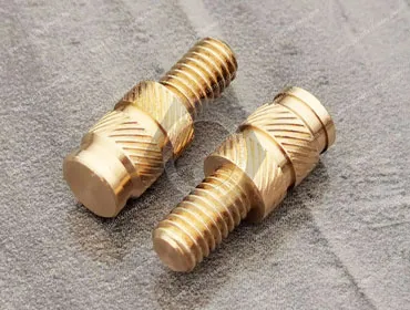
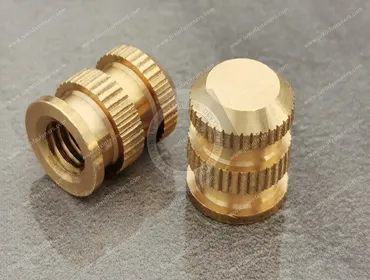
Brass heat-set threaded inserts
Tapered heat-set inserts
Straight-body threaded inserts
Knurled threaded inserts
Flanged threaded inserts
Ultrasonic threaded inserts
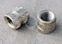
Stainless steel threaded inserts
303 stainless steel tapered heat-set inserts
Drawing-based custom threaded inserts
Applications include automotive plastic components, electronics, electrical equipment, industrial housings, commercial equipment and other injection-molded thermoplastic assemblies.
The correct insert, however, cannot be selected from thread size alone.
The insert geometry, polymer, molded-hole design, boss dimensions, installation process and final joint load must work together as a system.
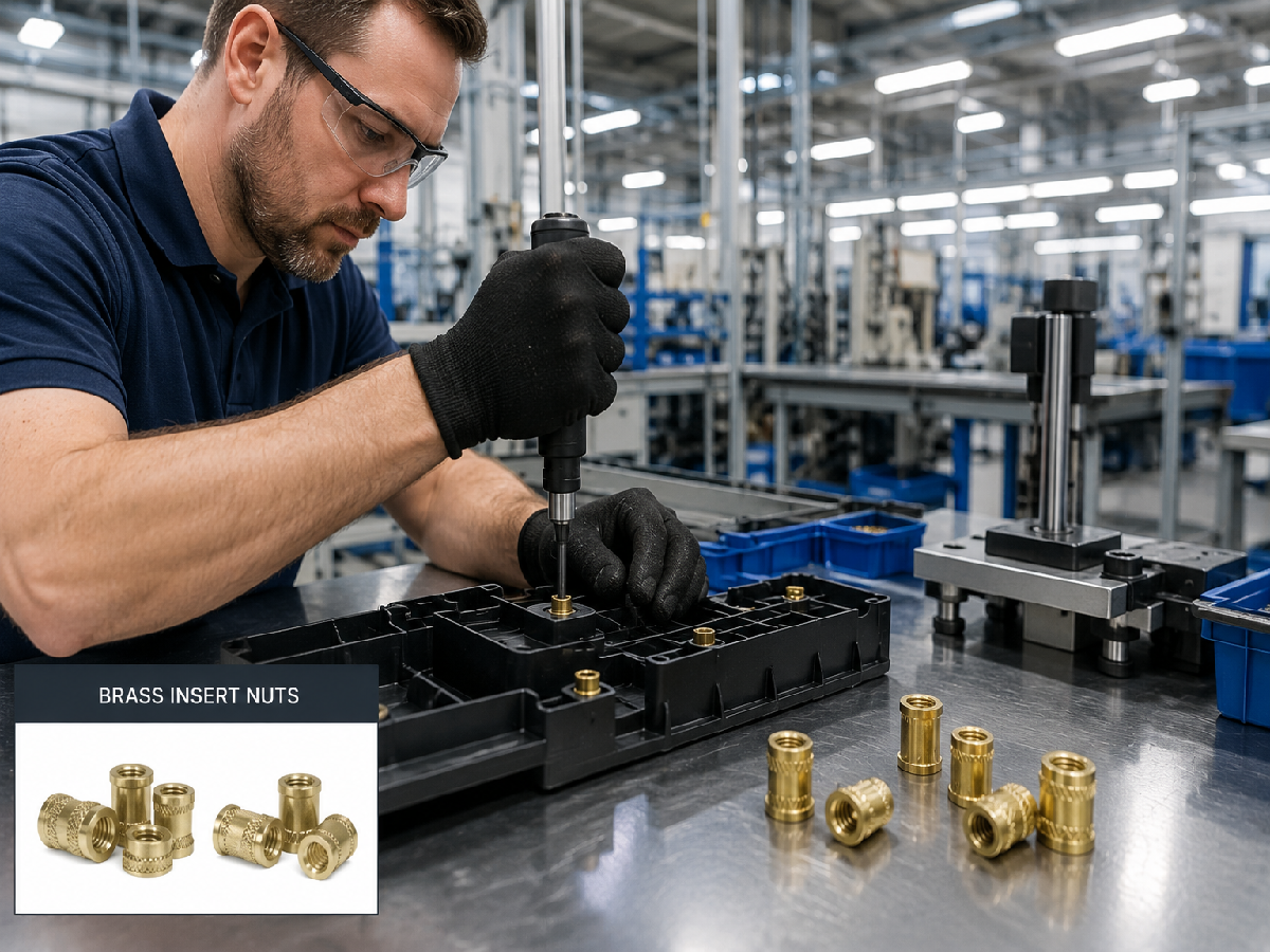
Threaded inserts are useful where manufacturers need a durable metal machine thread inside a molded thermoplastic component.
Potential applications include:
Lighting housings
Interior trim assemblies
Instrument-related components
Electronic module housings
Sensor housings
Control units
Plastic brackets
Covers and access panels
Electrical components
Automotive applications can involve vibration, temperature variation, repeated assembly and limited packaging space, making insert selection dependent on the complete component design.
Threaded inserts can be used in:
Electronic housings
Control modules
Communication equipment
Network equipment
Instrument housings
Power electronics
Charging equipment
Sensor enclosures
Industrial electronic devices
The insert provides a reusable metal thread while allowing the main enclosure to remain molded from engineering plastic.
Applications can include:
Electrical housings
Terminal enclosures
Switchgear components
Control equipment
Power conversion equipment
Insulating structures
Plastic mounting brackets
Depending on the device design and applicable material requirements, threaded inserts can be used in:
Instrument housings
Diagnostic equipment
Laboratory devices
Equipment covers
Adjustable assemblies
Serviceable plastic components
Material, cleaning, chemical exposure and application-specific regulatory requirements must be considered separately for medical equipment.
Threaded inserts are also applicable to:
Commercial food-service equipment
Appliances
HVAC controls
Lighting equipment
Equipment housings
Plastic handles
Covers
Service panels
The common requirement is a reusable threaded connection in a thermoplastic component.
Direct screw fastening into plastic can be effective when the application is designed for it.
It should not automatically be considered inferior.
However, a metal threaded insert becomes particularly useful when the assembly requires:
Repeated assembly and disassembly
A reusable machine thread
Higher tightening torque than the molded plastic thread can support
Better resistance to thread wear
Standard machine screws
Serviceable components
More repeatable assembly
The engineering decision should therefore not be:
“Metal insert or plastic thread—which is stronger?”
A better question is:
“How many times will this joint be assembled, what load must it carry, and what fastening method best matches the molded component?”
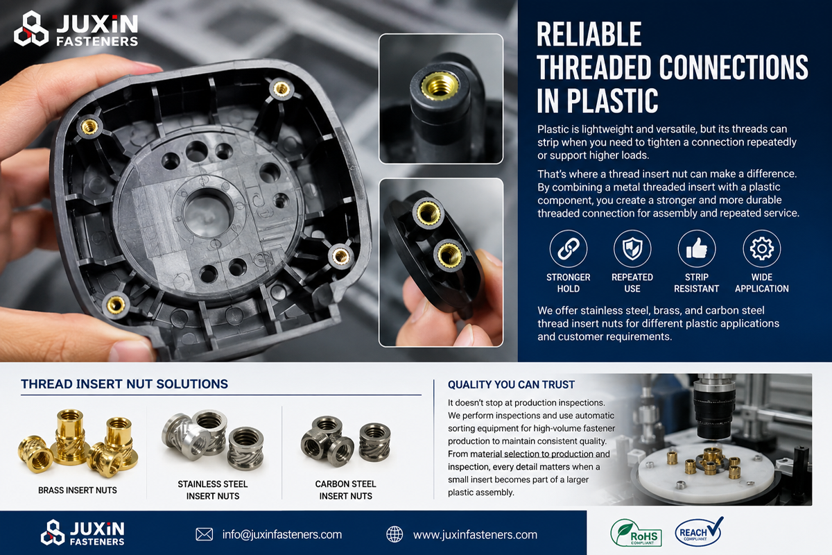
A heat-set insert is normally installed into a molded or prepared hole in a thermoplastic component.
During installation, heat is transferred into the metal insert.
The surrounding thermoplastic softens locally and flows around the external retention features of the insert.
As the polymer cools, it solidifies around those features and mechanically retains the insert.
Depending on the design, external retention geometry may include:
Straight knurls
Diagonal knurls
Diamond knurls
Annular grooves
Undercuts
Tapered sections
Flanges
The purpose of these features is not simply to make the insert look aggressive.
Different geometries influence how the polymer flows around the insert and how the finished joint resists rotational and axial loading.
Both methods can install a metal threaded insert into thermoplastic, but the energy is introduced differently.
Heat is transferred through the insert, softening the surrounding polymer so that the insert can move into the prepared hole.
This method is commonly used for thermoplastic components and can be integrated into manual or automated installation equipment.
Ultrasonic energy creates localized heating at the insert-plastic interface.
The softened polymer flows around the insert geometry as it is installed.
Ultrasonic installation can be useful in production systems designed specifically for this process.
The same insert geometry is not automatically optimal for every installation method.
Engineers should therefore define the intended installation process before finalizing the insert.
Mold-in inserts are placed into the mold before plastic injection.
Heat-set inserts are installed after the plastic part has already been molded.
Each method has advantages.
May be appropriate where:
Insert location is integrated into the molding process
The production system is designed for insert loading
The component geometry favors mold-in placement
However, insert loading can add complexity to molding operations.
May be appropriate where:
Post-mold installation is preferred
Different product variants use the same molded component
Insert installation is performed in a separate assembly process
The manufacturer wants to keep metal hardware out of the molding tool
The choice should be based on total manufacturing architecture rather than the insert price alone.
One of the most important principles in threaded insert design is:
The insert and plastic boss should be engineered together.
An excellent metal insert cannot compensate for a poorly designed plastic boss.
The final joint depends on:
Insert outside diameter
Insert length
Hole diameter
Hole depth
Boss outside diameter
Wall thickness
Polymer
Polymer condition
Installation temperature
Installation speed
Installation alignment
Final screw torque
Applied load
This is why generic statements such as “M4 heat-set insert pull-out strength” have limited engineering value without identifying the plastic and boss geometry.
Plastic bosses can crack during or after insert installation if the system generates excessive radial stress.
Possible causes include:
Hole diameter too small
Boss wall too thin
Incorrect insert geometry
Excessive installation force
Incorrect installation temperature
Insert misalignment
Polymer sensitivity
Molded-in stress
The solution is not simply to make the boss thicker.
Excessive material can create its own molding problems.
The boss should be designed according to the insert geometry, polymer and molding requirements.
Prototype evaluation is therefore useful before freezing the mold design.
The molded hole is not simply an empty space for the insert.
Its geometry influences how the thermoplastic moves during installation.
Important parameters can include:
Hole diameter
Hole depth
Taper
Lead-in geometry
Bottom clearance
Boss geometry
For tapered heat-set inserts, the relationship between the insert taper and receiving hole can assist alignment and controlled installation.
However, the recommended hole should be based on the actual insert design rather than a universal percentage of insert diameter.
Threaded inserts in plastic are commonly evaluated for two different failure modes.
Pull-out refers to axial force attempting to extract the insert from the plastic.
It is influenced by:
Insert length
External geometry
Polymer
Boss dimensions
Installation quality
Load direction
Torque-out refers to rotational loading attempting to spin the insert within the plastic.
It can be influenced by:
Knurl pattern
Insert diameter
Polymer engagement
Installation quality
Boss geometry
An insert optimized for rotational resistance is not automatically optimized for maximum axial pull-out.
The correct external geometry depends on the actual joint.
A common assumption is that a longer insert automatically creates a better joint.
Increasing engagement length can increase the amount of polymer interacting with the insert, but available boss depth, molding quality, installation process and load distribution also matter.
A longer insert can be unnecessary if:
The application load is low
Boss depth is limited
The component must remain thin
Additional length adds cost without functional benefit
The objective should be sufficient performance for the actual application, not the largest possible insert.
Aggressive knurling can increase mechanical engagement, but it can also require greater polymer displacement during installation.
If the boss geometry does not provide sufficient material and space for polymer flow, excessive external geometry may increase installation stress.
The design must balance:
polymer flow + rotational resistance + axial retention + boss integrity.
This is one reason insert geometry should not be selected only by comparing catalog photographs.
Brass is widely used for threaded inserts because it combines:
Good machinability
Good thermal conductivity
Useful corrosion resistance for many environments
Ability to manufacture detailed external retention features
Brass heat-set inserts are commonly used in:
Electronics
Automotive plastic components
Electrical equipment
Appliances
Industrial equipment
Consumer products
Material grade should be specified according to the customer drawing, application requirements and applicable material specification.
Where a specific brass alloy or international material standard is required, it should be identified in the RFQ rather than assumed.
Brass is not the only material option.
Stainless steel threaded inserts can be useful where the application requires characteristics such as:
Stainless material compatibility
Specific corrosion resistance
Different mechanical properties
Customer-specified material requirements
JUXIN FASTENERS also supports stainless steel threaded inserts for plastic, including drawing-based 303 stainless steel tapered heat-set insert configurations.
These are particularly relevant to OEM applications where a brass insert does not match the equipment material specification.
Because stainless steel and brass have different thermal and machining characteristics, installation parameters should not automatically be copied from one material to another.
Tapered inserts are useful where the geometry is designed to assist initial positioning and progressive installation into the receiving hole.
Potential benefits can include:
Easier initial alignment
Controlled insertion
Progressive polymer displacement
Compact installation geometry
However, the taper itself does not guarantee retention.
Performance still depends on:
External retention features
Insert length
Polymer
Hole geometry
Boss design
Installation process
For custom tapered inserts, the complete profile should therefore be controlled on the drawing.
Straight-body inserts can be appropriate where the receiving hole and installation process are designed around a cylindrical insert envelope.
Depending on the design, external features may provide resistance to axial and rotational movement.
The choice between tapered and straight-body inserts should be based on:
Plastic component geometry
Installation equipment
Required retention
Available boss dimensions
Production process
Neither configuration is universally superior.
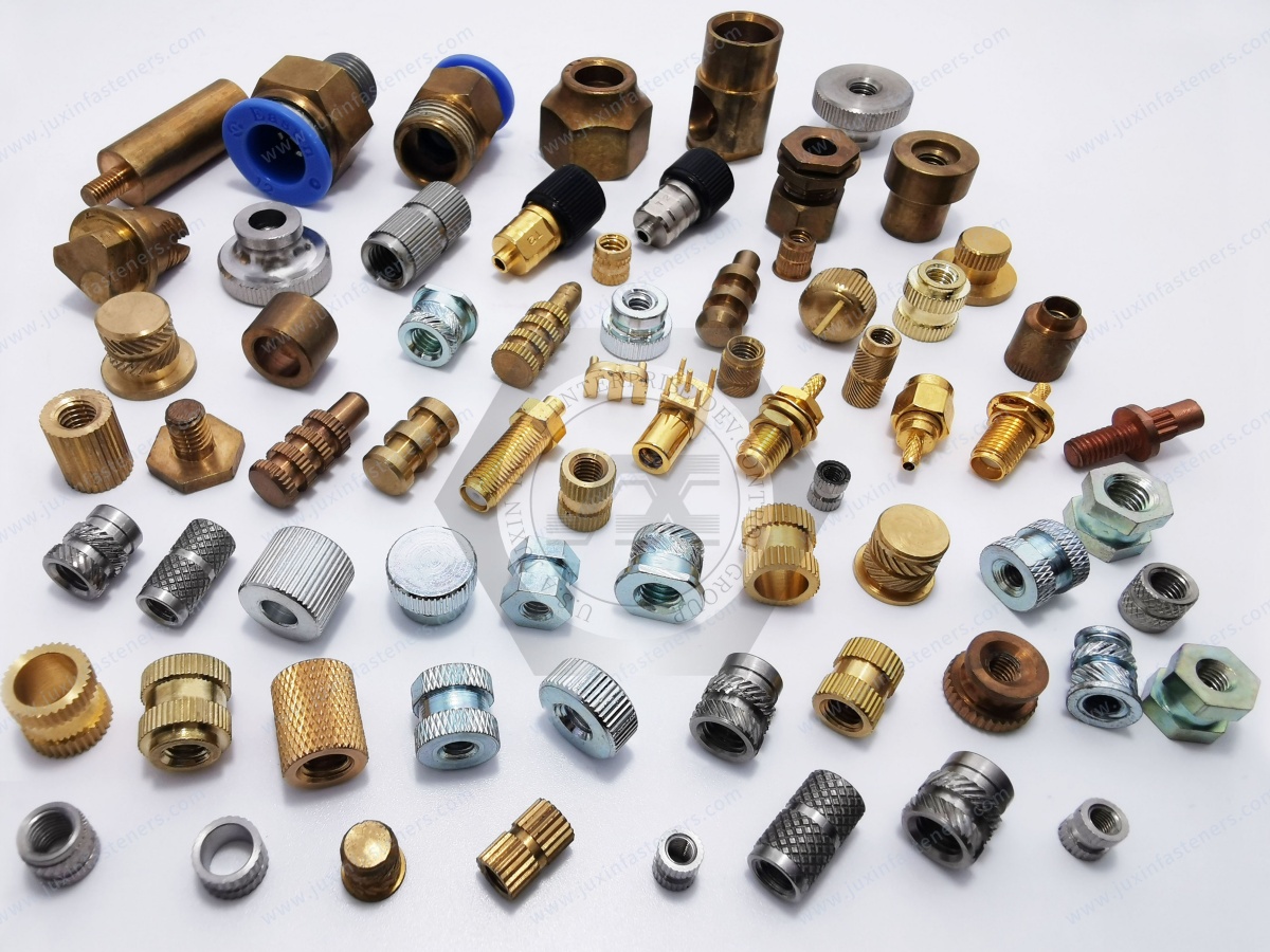
A flange changes how the insert interfaces with the plastic component and mating assembly.
Depending on the joint, a flange may:
Provide a defined seating surface
Limit insertion depth
Support selected axial loading conditions
Assist positioning
However, a flange also requires sufficient space around the top of the boss and may affect mating-component contact.
It should therefore be selected because the joint requires it, not simply because a flanged insert appears more robust.
Different thermoplastics respond differently to heat and mechanical loading.
ABS is widely used in housings and molded equipment components.
Installation conditions should avoid excessive localized heating or boss deformation.
PC is used where impact resistance and dimensional characteristics are important.
The boss and installation process should be evaluated for the actual grade and molded condition.
Nylon materials such as PA6 and PA66 are widely used in automotive, electrical and industrial components.
Moisture condition, material grade and reinforcement can affect mechanical behavior.
PBT is common in electrical, electronic and automotive components.
Insert design should account for the actual material grade and any reinforcement.
Glass reinforcement can significantly change material behavior compared with an unfilled polymer.
The same insert and installation settings should not automatically be used for both materials.
For reinforced plastics, prototype installation and testing become particularly important.
A procurement request such as:
“M5 brass insert for nylon”
still leaves major engineering variables undefined.
Nylon may refer to:
PA6
PA66
Reinforced nylon
Unfilled nylon
Different moisture conditions
Different molding grades
Likewise, the same M5 internal thread can be manufactured with many different:
Outside diameters
Lengths
Knurl patterns
Tapers
Flanges
A useful RFQ should therefore describe both the insert and the plastic assembly.
There is no single correct heat-set installation temperature for all thermoplastics.
The appropriate process depends on:
Polymer type
Polymer grade
Insert material
Insert mass
Insert geometry
Installation equipment
Installation speed
Boss geometry
Excessive heat can damage or deform the plastic.
Insufficient heat can require excessive insertion force and prevent proper polymer flow.
For production applications, installation settings should be developed and validated using the actual molded component and insert.
Temperature alone does not define the heat-set process.
Installation speed influences how much time the polymer has to soften and flow around the insert.
If installation is too fast for the thermal condition, the insert may push material rather than allowing controlled flow.
If the process is unnecessarily slow, productivity can suffer and excessive heat exposure may affect the component.
The process should therefore balance:
temperature + time + force + insertion speed.
This is particularly important when moving from manual prototype installation to automated production.
A threaded insert can be mechanically secure but still cause assembly problems if its final position is incorrect.
Potential issues include:
Insert sitting above the boss
Insert installed too deeply
Mating component not seating correctly
Screw engagement changing
Cosmetic problems
Assembly stack-up variation
For critical applications, final insert position should therefore be included in the installation validation.
One of the most expensive mistakes in plastic fastening occurs when the threaded insert is selected after the injection mold has already been finalized.
By that stage:
Boss diameter is fixed
Hole diameter is fixed
Hole depth is fixed
Wall thickness is fixed
Nearby ribs may restrict access
Installation tooling clearance may be limited
The insert supplier is then forced to find a component that fits an already constrained geometry.
A better development sequence is:
Joint Requirement → Insert Selection → Boss Design → Mold Review → Prototype → Installation Validation → Production
For new OEM projects, selecting the insert before freezing the mold can reduce redesign risk.
Both technologies have valid applications.
| Design Requirement | Threaded Insert | Screw Directly Into Plastic |
|---|---|---|
| Repeated servicing | Often advantageous | Depends on screw and plastic design |
| Machine screw required | Yes | Usually no |
| Additional installation operation | Yes | Often not required |
| Metal thread | Yes | No |
| Initial component count | Higher | Potentially lower |
| Long-term thread reuse | Often advantageous | Application dependent |
| Best use | Serviceable or controlled threaded joint | Cost-sensitive or limited-cycle assembly |
The correct choice should consider the total life of the product rather than only initial assembly cost.
Design engineers should begin with these questions:
What thermoplastic is being used?
Identify the actual polymer and grade where possible.
Is the plastic reinforced?
Filled and unfilled materials can behave differently.
What thread is required?
Define metric or inch thread, diameter and pitch.
How many assembly cycles are expected?
Repeated servicing can justify a metal insert.
What axial and rotational loads must the joint resist?
This influences insert length and retention geometry.
How much space is available for the boss?
The boss and insert must be designed together.
What installation process will be used?
Heat-set, ultrasonic, mold-in or another method?
What insert material is required?
Brass, stainless steel or another drawing-specified material?
These questions provide a much better starting point than selecting only by internal thread size.
For accurate evaluation and quotation, procurement teams should provide:
2D drawing
3D model where available
Internal thread size
Thread pitch
Insert length
Insert outside diameter
Flange requirement if applicable
Insert material
Plastic material
Plastic grade where known
Glass-filled or unfilled condition
Boss dimensions
Molded-hole dimensions
Installation method
Surface treatment if required
Prototype quantity
Annual production quantity
Inspection requirements
Packaging requirements
If an existing insert is being replaced, providing both the insert drawing and plastic-part information can help prevent dimensional substitutions that appear equivalent but perform differently.
Unit price is only one part of the sourcing decision.
For production threaded inserts, compare:
Material
Thread quality
Outside diameter
Length
Knurl geometry
Taper
Flange dimensions
Burr control
Dimensional consistency
Packaging
Lot identification
Drawing revision control
Sample-to-production repeatability
A lower-cost insert can become expensive if dimensional variation causes installation problems, plastic scrap or assembly-line interruptions.
Standard inserts are suitable for many applications.
Custom geometry may be appropriate where the OEM requires:
Special outside diameter
Restricted boss size
Non-standard length
Special taper
Special knurl pattern
Special flange
Inch-series thread
Non-standard thread
Stainless steel construction
Drawing-specific geometry
JUXIN FASTENERS supports drawing-based threaded inserts and CNC-machined insert components for OEM applications.
For custom projects, the most useful starting point is a drawing plus information about the plastic material and installation process.
A practical development path for threaded insert applications can follow:
Application Requirement → Polymer Selection → Insert Selection → Boss & Hole Design → Sample Installation
→ Pull-Out / Torque / Assembly Evaluation → Golden Sample Approval → Production
The exact validation method should be defined according to the customer's product and engineering requirements.
JUXIN FASTENERS supports OEM manufacturers, product developers, injection molders,
contract manufacturers and industrial supply chains with standard and drawing-based threaded insert solutions.
This page serves as the engineering entry point for threaded inserts used in thermoplastic assemblies.
Related product and solution pages can include:
Brass Heat-Set Threaded Inserts — for thermoplastic housings and general molded plastic assemblies
303 Stainless Steel Tapered Heat-Set Inserts — for OEM applications requiring stainless steel threaded inserts
Ultrasonic Threaded Inserts for Plastic — for ultrasonic insertion processes
Flanged Threaded Inserts for Plastic — for applications requiring a defined seating surface
Threaded Inserts for PA66 and Nylon Components — material-specific design considerations
Threaded Inserts for ABS and Polycarbonate Housings — electronics and enclosure applications
Threaded Inserts for Automotive Plastic Components — automotive lighting, interiors and electronic housings
Nylon and Engineering-Plastic Fasteners — screws, nuts, washers, spacers and PCB hardware
Custom CNC-Machined Components — drawing-based non-standard inserts and fastening components
As these individual pages are developed, they should link back to this engineering guide while targeting their own product, material or application-specific long-tail searches.
If you are designing or sourcing threaded inserts for:
Automotive plastic components
Automotive lighting
Electronic housings
Electrical equipment
Communication equipment
Medical equipment
Appliances
HVAC equipment
Commercial food-service equipment
Industrial electronics
Injection-molded plastic assemblies
send us your 2D drawing, 3D model where available, thread specification, insert material, plastic material,
boss dimensions, installation method and estimated quantity.
If you are still designing the plastic boss, send us the available assembly information before the mold geometry is finalized.
JUXIN FASTENERS can evaluate brass heat-set inserts, stainless steel threaded inserts, tapered inserts,
ultrasonic insert configurations and drawing-based custom threaded inserts according to the application requirements.
JUXIN FASTENERS
Website: www.juxinfasteners.com
Engineering & RFQ: info@juxinfasteners.com
Product Packaging
Packaging Standard
At Juxin Fasteners, we apply standardized export packaging to ensure product protection, traceability, and compliance with international logistics requirements.
1. Standard Export Packaging
Unless otherwise specified, all products will be packed according to our factory standard export packaging, which includes:
Moisture-resistant inner protection
Poly bag or small box packing as required
Reinforced export cartons
Clear labeling with part number, specification, batch number, and quantity
Palletizing for sea or air shipment when necessary
Our standard packaging is designed to ensure safe transportation, efficient warehousing, and long-distance international shipping.
2. Customized Packaging Options
We also provide customized packaging solutions according to customer requirements, including but not limited to:
Private labeling
Customized barcodes
Specific carton dimensions
Retail packaging
Special pallet configuration
Customer-specific marking and identification
So that you know, customized packaging may involve additional costs and extended lead time depending on the complexity of the requirements.
3. Compliance & Quality Assurance
All packaging processes are controlled under our ISO 9001 quality management system to ensure consistency, traceability, and product integrity throughout the supply chain.
Product Pictures
Contact Us
Tel.:
+86 020 8621 0320
+86 020 3121 6067
E-mail:
Technical Support:
Navigation
SEND INQUIREY