Call Us
+86 136 6007 9809
Call Us
+86 136 6007 9809

Industrial original equipment manufacturers (OEMs) designing electronic enclosures, automotive interior modules, control housings, appliance housings,
industrial equipment, and other thermoplastic assemblies frequently encounter the limitations of direct polymer threads.
Product Specification
Industrial original equipment manufacturers (OEMs) designing electronic enclosures, automotive interior modules, control housings, appliance housings,
industrial equipment, and other thermoplastic assemblies frequently encounter the limitations of direct polymer threads.
While molding internal threads directly into plastic components can be practical for selected applications, repeated assembly and disassembly,
installation torque, joint loading, vibration, environmental exposure, and long-term deformation can make direct plastic threads unsuitable for some designs.
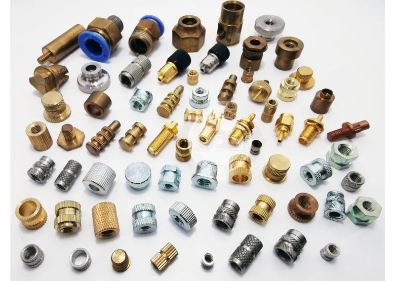
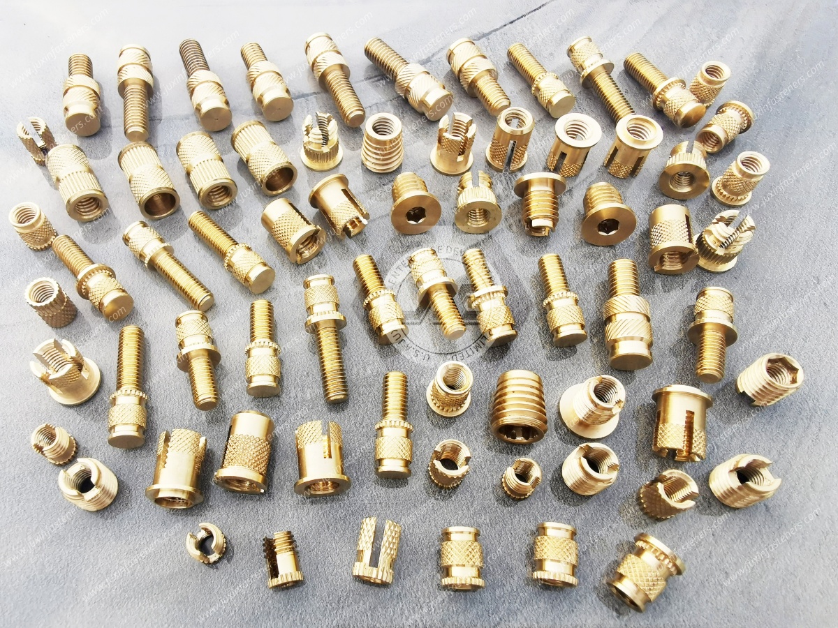
Specifying threaded inserts for plastic—including heat-set inserts, brass heat-set inserts, ultrasonic inserts,
molded-in inserts, and expansion inserts—can provide a metallic internal thread within a thermoplastic housing.
This approach can be useful when the engineering requirement calls for a more durable mating thread than the host plastic can provide by itself.
However, successful component integration requires evaluating the insert design, installation technology, host thermoplastic, boss geometry, hole diameter, installation process,
thread specification, and application loading rather than treating inserts as generic hardware.
The performance of an insert is determined by the interaction between the metal insert + plastic boss + installation process + mating fastener + application environment.
JUXIN FASTENERS supports industrial fastening and custom component requirements through engineering review, manufacturing coordination,
multi-SKU bill of materials (BOM) consolidation, and production quality control. This guide examines the engineering principles, installation techniques,
material considerations, product-family differences, and procurement requirements involved in specifying threaded inserts for plastic OEM assemblies.
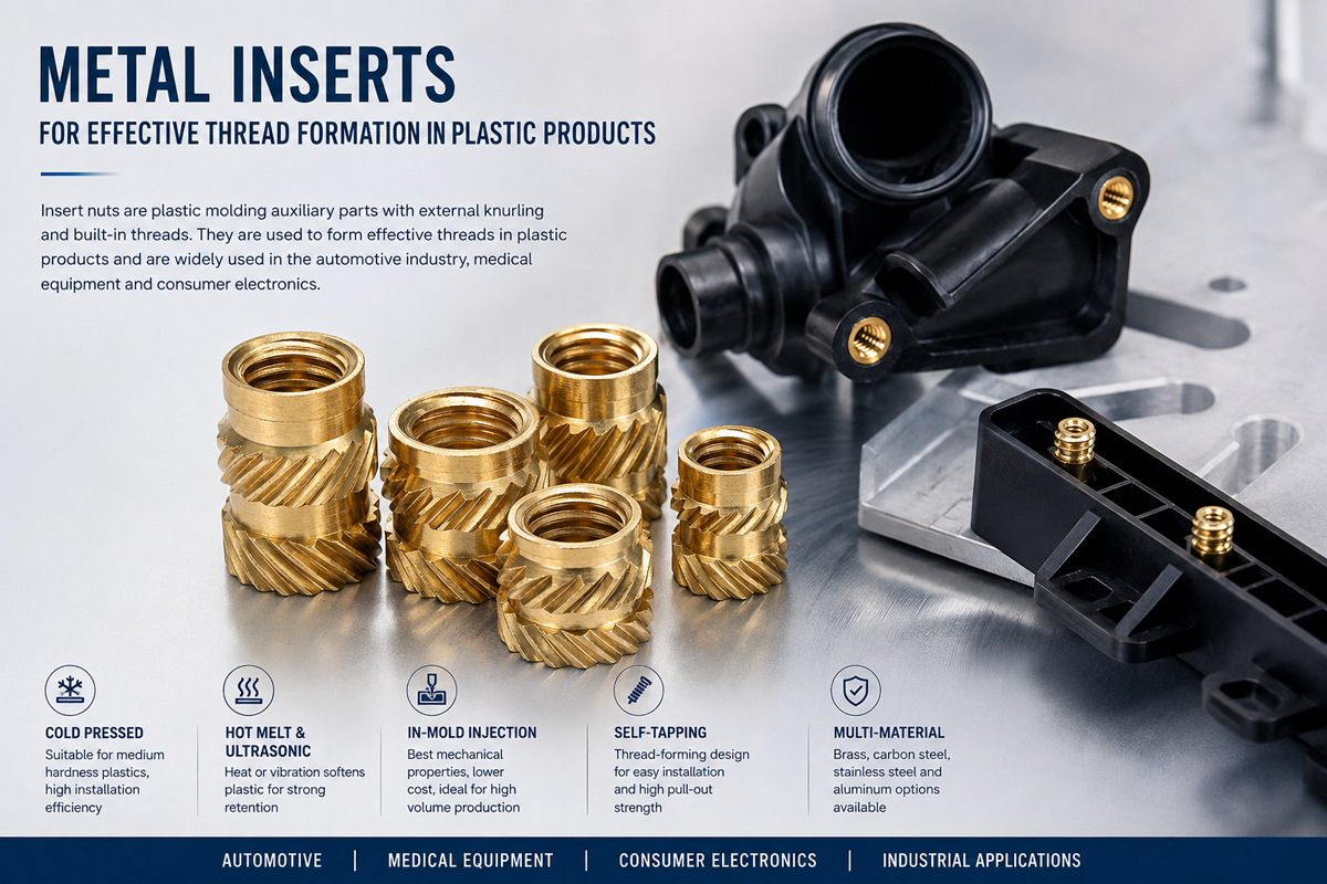
Design engineers can consider metal threaded inserts for plastic housings when direct polymer threads may not provide the required assembly durability, thread integrity, or fastening architecture.
Typical reasons include:
Frequent assembly and disassembly cycles where direct polymer threads may experience wear or deformation over repeated installation.
Joint requirements where the host plastic's direct internal thread may not provide sufficient resistance to the expected installation or service conditions.
Securing components to thermoplastic housings using machine screws or bolts where a durable internal metal thread is preferred.
Improving thread consistency in molded plastic components where the required thread interface is better provided by a separate insert.
Creating a standardized metallic thread interface inside a polymer housing while retaining the weight, design, and manufacturing advantages of the plastic enclosure.
Supporting repair, service, or repeated assembly requirements where preserving the mating thread is an important design consideration.
Providing a threaded mounting interface in plastic components where direct molded threads or self-tapping solutions are not appropriate for the application.
The important engineering question is not simply:
"Should I use a threaded insert?"
It is:
"Does the selected insert, installation method, boss geometry, host material, and mating fastener provide the required joint performance for this specific application?"
Directly molded or machined plastic threads can be useful in many applications, particularly where loading and assembly requirements are moderate.
However, engineers should reconsider a direct polymer thread when the design involves:
Frequent assembly and disassembly
Repeated service access
Higher installation torque
Higher joint loading
Vibration or cyclic loading
Long-term preload requirements
Tight thread dimensional requirements
High-temperature exposure
Significant environmental variation
A requirement for a durable metallic mating thread
The correct solution may be a threaded insert, but the decision should be made from the actual joint requirements rather than assuming that every plastic thread needs reinforcement.
Designing joints in thermoplastic components involves distinct mechanical challenges. Relying entirely on self-tapping screws, direct molded threads, or machined plastic threads can create specific engineering concerns.
Under repeated manual or automated screw insertion, polymer threads can wear, deform, or lose dimensional integrity depending on the material, geometry, installation conditions, and service environment.
A metallic threaded insert provides a metal mating thread that can change the wear behavior of the joint compared with a direct polymer thread.
However, the insert does not automatically guarantee unlimited assembly cycles or a specific service life.
Two important insert-retention failure modes are:
Torque-out: the insert rotates within the surrounding plastic during tightening or removal.
Pull-out: the insert moves out of the plastic boss under an axial or tensile loading condition.
These failure modes depend on several variables, including:
Insert geometry
External knurling or retention features
Host resin
Boss dimensions
Hole diameter
Installation process
Installation quality
Joint loading
Temperature
Environmental exposure
Optimized insert geometry and properly controlled installation can improve retention, but engineers should not assume that a particular knurling pattern or hole size automatically eliminates torque-out or pull-out.
Application-specific validation may be required where retention performance is critical.
Complex internal thread features can complicate mold design and manufacturing.
Post-mold insert installation can allow the plastic housing to be molded with a simpler boss or hole structure, followed by insert installation.
This can be attractive for designs where a separate metallic thread is required without incorporating a more complex molded-thread geometry.
The final manufacturing route should be evaluated against:
Part geometry
Production volume
Mold design
Insert loading
Installation cycle
Automation requirements
Quality control
Overall production cost
Different insert technologies solve different installation and manufacturing requirements.
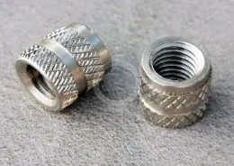
Heat-set inserts, also called thermal inserts or heat-staked inserts, are installed by heating the insert or surrounding interface and pressing the insert into a prepared thermoplastic hole.
The softened plastic flows around the external retention features of the insert and solidifies after cooling.
This method is widely considered for thermoplastic housings where controlled thermal insertion is compatible with the resin and component design.
The actual retention performance depends on the insert geometry, plastic material, hole dimensions, installation temperature, insertion force, boss design, and process control.
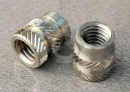
Ultrasonic inserts are installed using ultrasonic energy to soften or melt the surrounding thermoplastic locally while the insert is driven into the component.
Ultrasonic installation can offer short process cycles and may be suitable for production environments where the equipment, thermoplastic resin, insert geometry, and part design are compatible.
Process parameters must be developed for the actual combination of:
Insert + Resin + Boss + Hole + Equipment
rather than copied from an unrelated application.
Molded-in inserts are positioned inside the injection mold before or during resin injection.
The plastic is molded around the insert, creating an integrated threaded interface.
This method can provide an integrated assembly, but it introduces additional manufacturing considerations such as:
Insert placement
Mold design
Insert loading
Position accuracy
Resin flow
Mold protection
Production cycle
Automation
Molded-in inserts may therefore be attractive for high-volume products where the tooling and production architecture justify the process.
Expansion inserts use a mechanical retention principle in which installation causes part of the insert to expand or engage the surrounding plastic.
They can be considered where thermal or ultrasonic installation is not preferred or where the housing design is better suited to mechanical insertion.
The actual retention mechanism depends on the insert design and host material.
The choice of installation technology should be based on the product architecture and manufacturing process.
| Insert / Installation Type | Basic Principle | Potential Advantages | Key Engineering Considerations |
|---|---|---|---|
| Heat-Set Insert | Thermal softening of thermoplastic followed by insert installation | Suitable for many thermoplastic housing designs; can support controlled insertion | Resin behavior, temperature, hole size, boss geometry, installation force and cooling |
| Ultrasonic Insert | Localized thermoplastic softening using ultrasonic energy | Potentially short cycle time and automation compatibility | Equipment capability, resin response, insert geometry, horn/tooling, process parameters |
| Molded-In Insert | Insert incorporated during molding | Integrated insert placement during molding process | Mold design, insert loading, alignment, resin flow, tooling cost and production volume |
| Expansion Insert | Mechanical expansion or engagement within the plastic | No thermal or ultrasonic insertion may be required | Hole geometry, expansion mechanism, host material and installation method |
There is no universally superior insert technology.
The correct choice depends on:
Plastic Resin + Part Geometry + Production Volume + Installation Equipment + Required Retention + Cost + Assembly Process
An insert is only one part of the joint.
The surrounding thermoplastic boss is equally important.
Design engineers should evaluate the boss as a complete structural interface rather than specifying the insert independently.
Insufficient material around the insert can increase the risk of boss deformation or cracking during installation or service.
The required wall geometry depends on:
Host polymer
Insert diameter
Insert geometry
Boss geometry
Installation process
Joint loading
Environmental conditions
Therefore, a universal boss wall thickness should not be applied to every insert and resin combination.
Pre-molded or drilled hole dimensions are critical to installation.
An oversized hole may reduce the amount of surrounding plastic engaging the insert's external retention features.
An undersized hole may increase installation force or create excessive stress in the boss.
Hole diameter should therefore be developed against the specific insert, resin, installation process, and supplier recommendation.
Hole depth should accommodate the insert geometry and installation process.
The design should also consider:
Insert length
Bottom clearance
Screw length
Screw penetration
Blind-hole geometry
Potential interference
Installation method
Large bosses can create localized material accumulation in injection-molded parts and may contribute to sink marks or other cosmetic molding issues.
Core-out techniques, wall transitions, draft, and appropriate boss geometry can help manage these molding considerations.
The final geometry should be reviewed together with the injection-molding process rather than treating the insert boss as an isolated fastening feature.
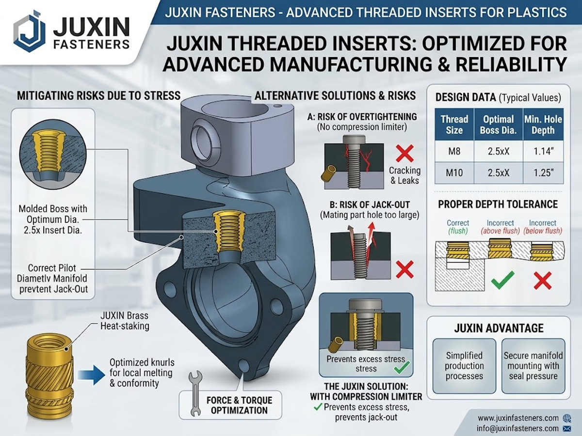
Yes, threaded inserts can be used in selected glass-filled thermoplastic applications, but the installation process must be developed for the actual resin and insert combination.
Glass-filled polymers can behave differently from unfilled thermoplastics in terms of stiffness, flow behavior, thermal response, and machining or molding characteristics.
Engineers should therefore evaluate:
Exact resin grade
Glass-fiber content
Boss geometry
Hole dimensions
Insert geometry
Installation method
Installation temperature where thermal insertion is used
Insertion force
Potential boss cracking
Required retention performance
The correct process parameters should come from validated application development rather than a generic setting for all glass-filled plastics.
Threaded inserts are powerful design tools, but they are not automatically the best solution.
An insert may not be appropriate when:
The joint is low-load and rarely assembled.
A direct molded plastic thread already satisfies the validated requirements.
A self-tapping or thread-forming solution is more appropriate for the production process.
The plastic wall or boss is too small to accommodate the insert safely.
The component geometry does not allow the required installation method.
Production volume does not justify the additional insert installation process.
The application requires a different fastening architecture.
The insert would add unnecessary cost or assembly complexity.
The purpose of a threaded insert is not simply to make a plastic part "stronger."
Its primary design value is to create a defined threaded interface within a polymer component when the application requirements justify it.
A threaded insert is part of a complete fastening assembly.
The mating fastener must be selected together with the insert.
Depending on the application, engineers may use:
Metal machine screws
Plastic screws
Nylon screws
Plastic machine screws
Nylon machine screws
Bolts
Washers
Nylon washers
Plastic flat washers
Shoulder washers
Spacers
Nylon spacers
Plastic nuts
Nylon nuts
Other polymer fastening components
For example:
Screw → Washer → Plastic Housing → Threaded Insert
may be used when a screw must attach a component to a thermoplastic housing.
Where physical separation is required:
Screw → Spacer → Component → Threaded Insert
may form part of the mounting architecture.
For PCB applications, engineers may instead use:
PCB → Standoff / Spacer → Enclosure or Bracket
with threaded interfaces depending on the selected standoff configuration.
This is why threaded inserts should not be evaluated as isolated hardware. The mating screw, washer, spacer, standoff, housing, and joint requirements all influence the final fastening architecture.
The insert's internal thread should match the mating screw or bolt.
Depending on the application, OEM requirements may include:
ISO metric threads
DIN-related dimensional requirements
ASME/ANSI Unified Thread requirements
UNC
UNF
Customer-specific thread specifications
The RFQ should clearly identify:
Nominal thread size
Pitch
Thread designation
Thread tolerance
Insert dimensions
Mating fastener
Relevant drawing standard
Do not specify only "M6 insert" or "1/4-inch insert" when the application requires a controlled thread tolerance.
JUXIN FASTENERS should not claim universal compliance with every ISO, DIN, ASME, or ANSI standard unless the specific insert and drawing requirements have been verified.
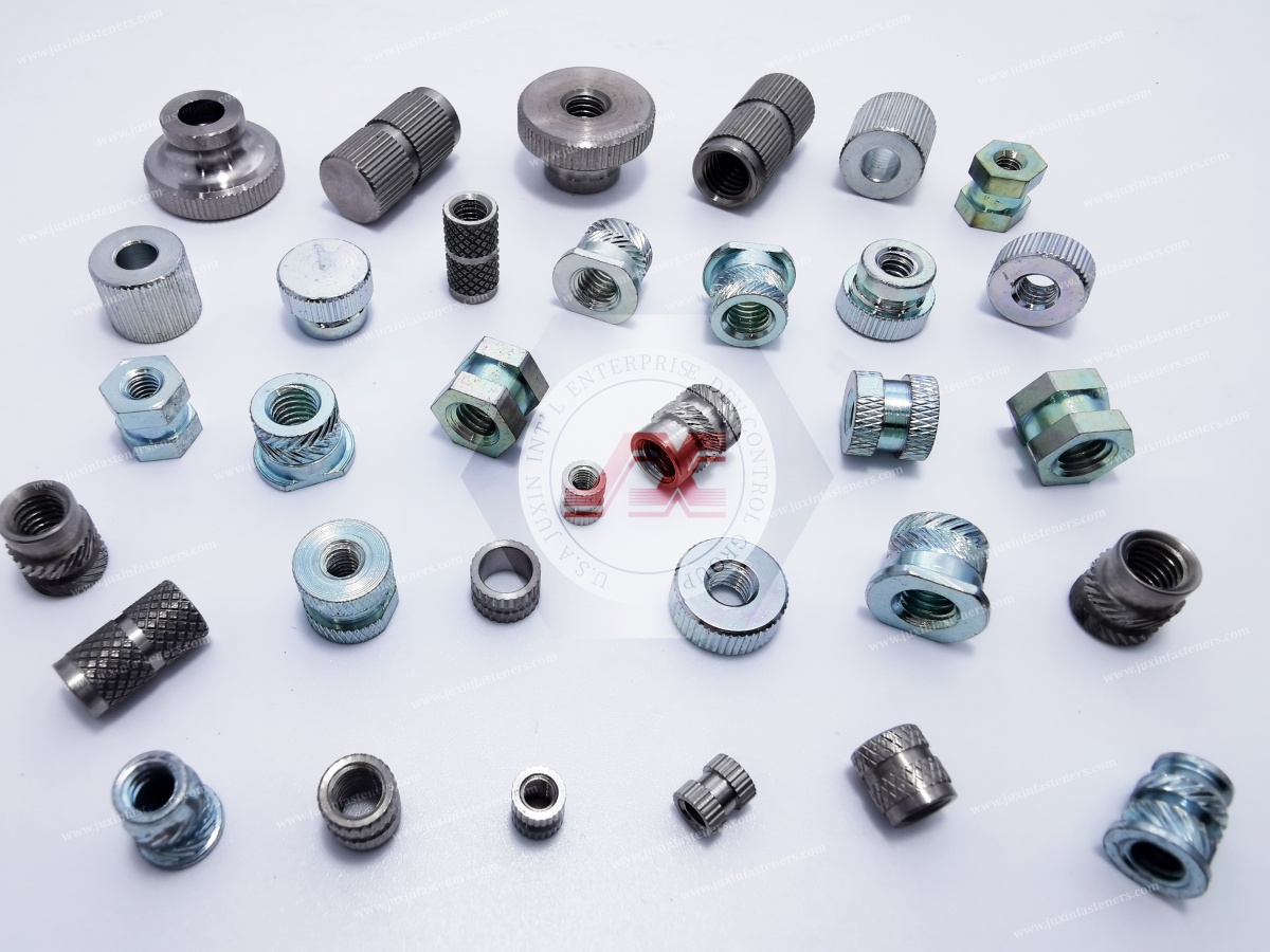
Threaded inserts for plastic are commonly produced from metallic materials selected according to the application.
Potential material categories may include:
Brass
Stainless steel
Other customer-specified metals
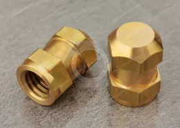
Brass threaded inserts are widely used for thermoplastic housings and electronic components where a metallic internal thread is required.
Brass can provide useful machinability and a suitable metallic mating interface for many applications.
The exact brass grade should be specified according to the product drawing and application requirements.
Stainless steel inserts may be considered when corrosion resistance or other material requirements justify their use.
The specific stainless grade should be selected according to the actual environment rather than assuming that all stainless steels have identical corrosion performance.
If the insert requires plating or surface treatment, the RFQ should specify:
Base metal
Surface treatment
Coating type
Color or appearance
Environmental requirements
Applicable customer specifications
A coating should not be assumed to provide a particular corrosion rating unless verified data is available for the actual product and process.
Submitting a comprehensive Request for Quotation (RFQ) streamlines technical evaluation, tooling review, sampling, and production planning.
Procurement managers and design engineers should prepare a complete technical package covering:
Specify the insert type, such as:
Heat-set brass insert
Heat-set threaded insert
Ultrasonic insert
Molded-in insert
Expansion insert
Other custom threaded insert
Compression limiter where a non-threaded metallic sleeve is required for a separate design function
Also specify the required internal thread standard.
Provide 2D technical drawings and 3D CAD files specifying:
Overall insert length
Outer diameter
Internal thread size
Thread pitch
Thread designation
External retention geometry
Knurling or other retention features
Chamfers
Critical dimensions
Manufacturing tolerances
Specify:
Base metal
Brass or stainless-steel grade where required
Surface treatment
Plating requirements
Appearance
Any customer-approved material alternatives
The plastic housing is just as important as the insert.
Provide:
Exact thermoplastic resin
Resin grade
Unfilled or reinforced material
Glass-fiber content where applicable
Part geometry
Boss dimensions
Hole diameter
Hole depth
Operating environment
Temperature exposure
Chemical exposure
Expected loading
Assembly frequency
Identify the intended installation process:
Heat-staking
Thermal insertion
Ultrasonic insertion
Molded-in
Mechanical / expansion installation
If the installation method has not yet been selected, provide the production volume, housing material, part geometry, and assembly requirements so the appropriate method can be evaluated.
Procurement teams should also provide:
Annual volume
Initial order quantity
Forecast requirements
Multi-SKU BOM
Packaging requirements
Labeling requirements
Sample requirements
Inspection requirements
Delivery expectations
Before releasing an insert and plastic housing combination for production, engineers should verify the complete assembly.
Confirm:
Insert type
Material
Thread size
Thread pitch
Overall dimensions
External retention geometry
Surface treatment where required
Confirm:
Resin family
Resin grade
Reinforcement
Moisture/environmental conditions
Molding process
Boss geometry
Verify:
Installation method
Hole dimensions
Equipment compatibility
Process control
Insert alignment
Potential boss damage
Consider:
Installation torque
Required clamping
Repeated assembly
Thread wear
Torque-out
Pull-out
Vibration
Long-term loading
Specific performance values should be validated for the actual insert, resin, geometry, installation process, and application.
Confirm:
Tooling feasibility
Mold design
Insert loading
Installation process
Automation requirements
Inspection method
Production scalability
The insert should be validated as a system, not as a standalone component:
Insert + Plastic Boss + Hole + Installation Process + Mating Fastener + Application Environment
For engineered plastic housings, supplier qualification should extend beyond the ability to quote a standard brass insert.
The supplier should be able to review:
Insert dimensions
Thread specifications
Retention geometry
Boss interface
Hole requirements
Installation method
Critical tolerances
OEM buyers should understand how the supplier controls:
Base metal
Material grade
Surface treatment
Purchased raw materials
Customer-specific material requirements
Evaluate whether the supplier can support:
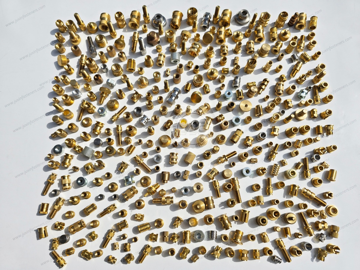
Standard threaded inserts
Custom insert geometry
Heat-set inserts
Ultrasonic inserts
Other applicable insert designs
Required tooling
Prototype quantities
Production volumes
Where the customer needs assistance with installation, the supplier should be able to discuss:
Host resin
Boss design
Hole dimensions
Insert geometry
Installation method
Process development
Prototype validation
The supplier should not simply provide generic installation parameters without considering the actual plastic and component design.
Depending on the drawing, inspection may include:
Dimensional verification
Thread checking
Visual inspection
Critical feature inspection
Material verification where required
Customer-specified inspection requirements
A capable OEM supplier should support the transition from:
Drawing → Prototype / Sample → Installation Evaluation → Validation → Production → Repeat Supply
Threaded inserts are often only one item within a larger plastic hardware BOM.
Where the supplier's actual manufacturing scope supports it, OEM customers may consolidate sourcing for:
Threaded inserts
Plastic screws
Nylon screws
Plastic bolts
Nylon bolts
Plastic nuts
Nylon nuts
Nylon washers
Plastic flat washers
Shoulder washers
Plastic spacers
Nylon spacers
PCB spacers
Threaded standoffs
This can simplify supplier management, packaging, shipment consolidation, quality communication, and forecast coordination.
International OEM sourcing also requires clear communication regarding:
Drawing revisions
Tooling
Samples
Installation trials
Production schedules
Packaging
Shipping
Quality issues
Forecast changes
Repeat orders
The right threaded-insert supplier should be evaluated according to its ability to understand the insert + plastic housing + installation process rather than simply supplying a metal threaded component.
Brass threaded inserts provide a metallic internal thread within a plastic component.
This can be useful where the design requires a more durable mating thread, repeated assembly, controlled thread geometry, or a different thread interface from the host polymer.
However, the actual improvement in joint performance depends on the insert design, host plastic, boss geometry, installation process, mating fastener, and application.
Heat-set inserts are installed using thermal energy to soften the surrounding thermoplastic before or during insertion.
Ultrasonic inserts use ultrasonic energy to locally soften the surrounding thermoplastic during insertion.
Both methods can be effective, but the appropriate method depends on the resin, insert design, housing geometry, equipment, production volume, and process requirements.
Yes, selected threaded inserts can be used in glass-filled thermoplastics.
However, reinforced polymers may behave differently from unfilled materials during insertion and molding.
The installation process should therefore be developed around the exact resin grade, reinforcement level, boss geometry, insert design, hole dimensions, and equipment.
This condition is commonly called torque-out.
Potential contributing factors include:
Incorrect hole dimensions
Insufficient boss geometry
Inadequate insert retention features
Unsuitable installation conditions
Excessive installation torque
Host-material limitations
Application loading
The specific root cause should be determined from the complete insert and housing design rather than assuming that one factor is always responsible.
Pull-out can occur when the axial load applied to the insert exceeds the retention capability of the insert/plastic interface.
Retention depends on:
Insert geometry
External retention features
Host resin
Boss dimensions
Installation quality
Loading direction
Temperature
Environmental conditions
A universal pull-out value should not be assumed without validated product and application data.
Custom threaded inserts can be designed around specified metric or inch-based thread requirements.
The actual thread standard, tolerance, insert dimensions, and material should be confirmed against the customer's technical drawing.
JUXIN FASTENERS should not claim universal compliance with every ISO, DIN, ASME, or ANSI requirement unless the specific product has been verified against the applicable standard.
A threaded insert may be considered when the application requires a defined machine-thread interface, repeated assembly, improved thread durability, or a different joint architecture.
A self-tapping or thread-forming screw may be more appropriate where the production process is optimized around direct installation into the thermoplastic and the resulting joint satisfies the application requirements.
No.
Direct molded threads can be suitable for selected applications.
A threaded insert becomes more attractive when the application requires characteristics that the direct polymer thread cannot reliably provide.
The engineering decision should consider assembly frequency, load, environment, manufacturing complexity, cost, and validation requirements.
A threaded insert primarily provides a threaded metal interface within a plastic component.
A compression limiter is generally a metallic sleeve or similar component designed to control compressive loading through a plastic assembly when a bolt or screw is tightened.
They can appear similar as cylindrical metallic components, but their engineering functions are different.
Yes, depending on the application.
A threaded insert can provide a metallic internal thread while the mating fastener can be plastic, nylon, or metal if the thread compatibility and mechanical requirements are suitable.
The complete joint should be evaluated for installation torque, thread compatibility, loading, wear, environment, and electrical requirements.
Procurement teams should provide:
2D technical drawings
3D CAD files
Insert type
Thread specification
Dimensions
Material
Surface treatment
Host plastic resin
Boss geometry
Hole dimensions
Installation method
Application environment
Annual volume
Initial order quantity
Packaging requirements
Inspection requirements
Multi-SKU BOM information
Complete information allows the supplier to evaluate manufacturability, installation requirements, tooling, inspection, and production planning before quotation.
Selecting threaded inserts for plastic, heat-set brass inserts, ultrasonic inserts, molded-in inserts, or expansion inserts requires more than selecting an insert based on thread size.
The engineering decision should consider:
Insert Type → Material → Thread → Host Plastic → Boss Design → Hole Geometry → Installation Method → Joint Requirements → Environment → Manufacturing → Inspection
For complete plastic fastening assemblies, engineers may also need to evaluate plastic screws, nylon screws, plastic bolts, nylon bolts, plastic nuts, nylon nuts, nylon washers,
shoulder washers, plastic spacers, PCB spacers, and threaded standoffs.
JUXIN FASTENERS supports OEM customers with drawing review, custom fastening component evaluation, manufacturing coordination, prototype/sample support, multi-SKU BOM sourcing, and production supply.
Submit your 2D/3D CAD files, technical requirements, host plastic information, installation method, annual volume projections,
and relevant application information to info@juxinfasteners.com for engineering review and an OEM quotation.
Product Packaging
Packaging Standard
At Juxin Fasteners, we apply standardized export packaging to ensure product protection, traceability, and compliance with international logistics requirements.
1. Standard Export Packaging
Unless otherwise specified, all products will be packed according to our factory standard export packaging, which includes:
Moisture-resistant inner protection
Poly bag or small box packing as required
Reinforced export cartons
Clear labeling with part number, specification, batch number, and quantity
Palletizing for sea or air shipment when necessary
Our standard packaging is designed to ensure safe transportation, efficient warehousing, and long-distance international shipping.
2. Customized Packaging Options
We also provide customized packaging solutions according to customer requirements, including but not limited to:
Private labeling
Customized barcodes
Specific carton dimensions
Retail packaging
Special pallet configuration
Customer-specific marking and identification
So that you know, customized packaging may involve additional costs and extended lead time depending on the complexity of the requirements.
3. Compliance & Quality Assurance
All packaging processes are controlled under our ISO 9001 quality management system to ensure consistency, traceability, and product integrity throughout the supply chain.
Product Pictures
Contact Us
Tel.:
+86 020 8621 0320
+86 020 3121 6067
E-mail:
Technical Support:
Navigation
SEND INQUIREY