Call Us
+86 136 6007 9809
Call Us
+86 136 6007 9809

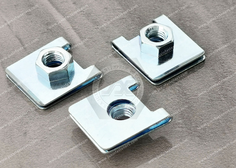
When a sheet-metal assembly requires a removable threaded attachment point near a panel edge, engineers may consider U-nuts,
J-nuts, and related clip-on spring nuts as alternatives to welding, tapping, or permanently installing a threaded insert.
Product Specification
When a sheet-metal assembly requires a removable threaded attachment point near a panel edge, engineers may consider U-nuts, J-nuts,
and related clip-on spring nuts as alternatives to welding, tapping, or permanently installing a threaded insert.
At first glance, U-nuts and J-nuts can appear functionally similar. Both can be installed from a panel edge and position a threaded or screw-engaging feature for subsequent assembly.
In practice, however, the correct choice depends on much more than whether the clip resembles the letter U or J.
Panel thickness, hole setback, throat depth, edge geometry, screw path, installation direction, available backside clearance,
clip retention and service requirements can all affect whether a particular spring-nut geometry fits the assembly.
For design engineers and OEM sourcing teams, the more useful question is therefore not simply:
“Should I use a U-nut or a J-nut?”
It is:
“Which edge-mounted spring-nut geometry correctly matches the panel, hole location, screw and available assembly envelope?”
JUXIN FASTENERS supplies clip-on nuts and spring fastener solutions for OEM sheet-metal applications.
Geometry, material, thread or screw interface, finish and dimensional requirements should be selected from the actual assembly conditions rather than from the product name alone.
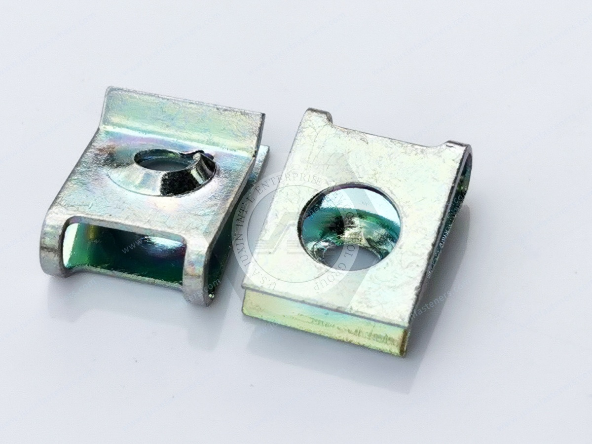
The practical difference is primarily geometric.
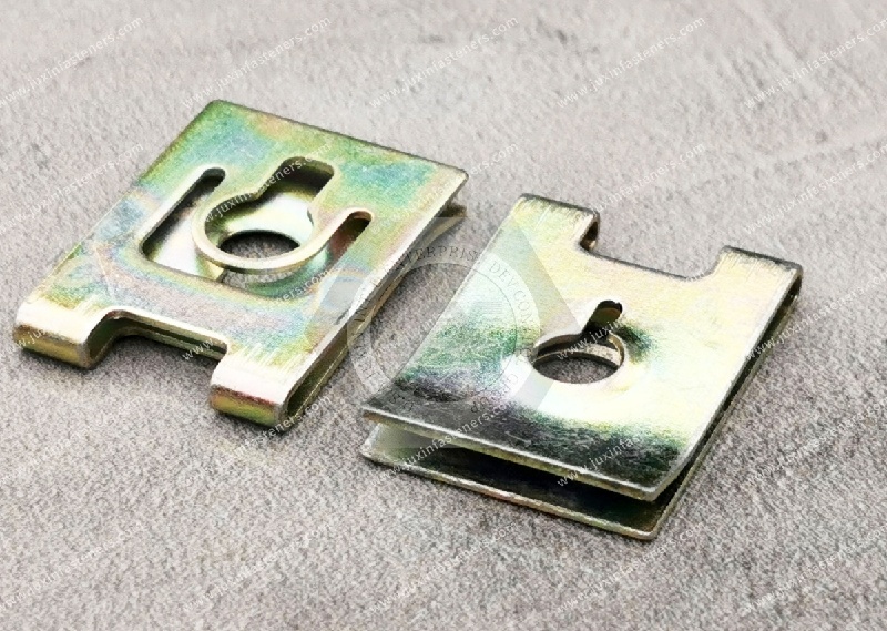
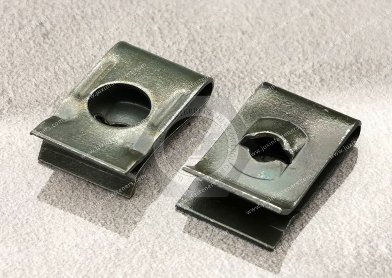
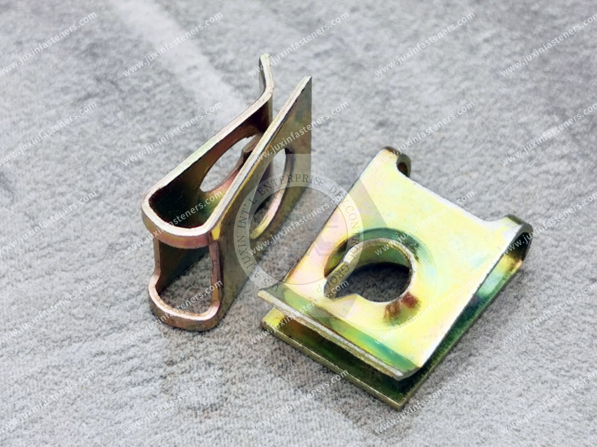
A typical U-nut wraps around a sheet-metal edge with two opposing legs, creating a U-shaped clip profile.
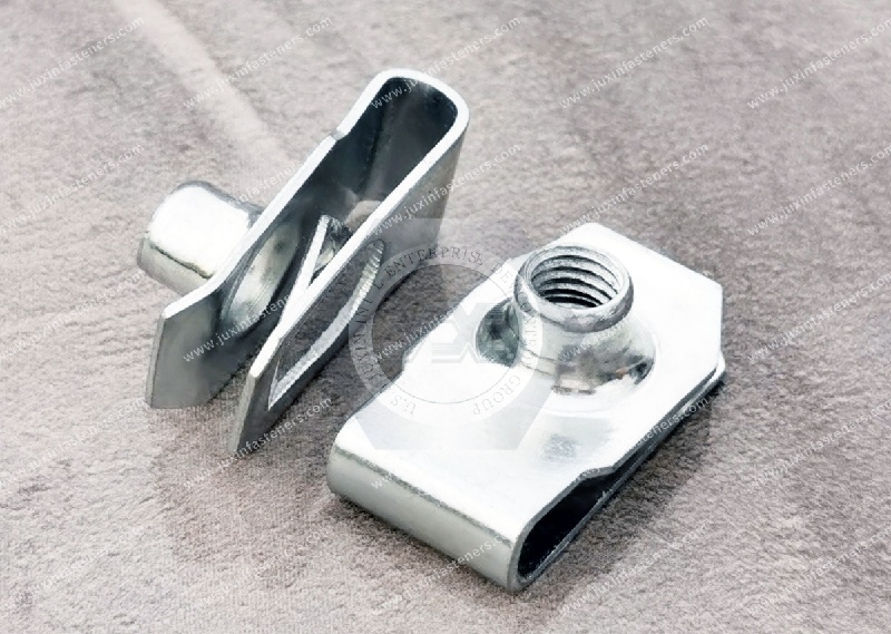
A J-nut uses an asymmetric or J-shaped configuration that can provide a different reach, access envelope or relationship between the panel edge and fastening location.
However, these names cover multiple commercial designs.
Not every U-nut has identical leg lengths, throat depth or thread construction, and not every J-nut places the fastening point in exactly the same way.
For OEM selection, the actual drawing is therefore more important than the category name.
Engineers should compare:
panel thickness;
clip opening or gripping range;
distance from the panel edge to the fastening location;
throat or reach dimension;
upper- and lower-leg geometry;
available clearance around the panel;
mounting-hole position;
screw approach direction;
thread or screw-engaging feature;
installation direction;
material and surface treatment.
This geometry-based approach prevents a common sourcing problem: two suppliers may both describe a component as a “U-nut,” while the parts are not dimensionally interchangeable.
A U-nut generally wraps around a panel edge using two opposing legs.
This configuration can be useful when the assembly provides sufficient space for the clip to straddle the panel and when the fastening feature must be positioned at a defined distance from the edge.
The critical design dimensions are not simply overall length and width.
For an engineering drawing or RFQ, the relationship between the clip and the panel is more important.
The clip must be compatible with the actual sheet thickness and its tolerance.
If the panel is outside the intended gripping range, the clip may not seat or locate as intended.
This is why specifying only “U-nut M6,” for example, would generally be insufficient for an OEM sourcing project. Thread designation alone does not define the panel interface.
Hole setback is the distance from the sheet edge to the required fastening location.
A U-nut with the correct thread but the wrong reach may position its threaded feature away from the panel hole.
This can create screw-starting difficulty, alignment problems or an assembly condition in which the screw forces the clip away from its intended position.
The throat or reach of the clip must correspond to the hole setback and surrounding panel geometry.
This dimension becomes especially important when the mounting hole is located farther from the sheet edge.
The opposing leg must have sufficient room to pass around and seat against the panel.
Nearby bends, ribs, brackets, welds, enclosure walls or other components can interfere with installation even when the nominal panel thickness and thread size appear correct.
A J-nut uses a different, typically asymmetric edge-clip geometry.
Depending on the specific design, this can help accommodate a different hole position, panel-edge configuration or assembly envelope than a conventional U-shaped clip.
The important engineering advantage is therefore not an assumed universal “offset load rating.” It is the ability to select a geometry that fits a particular edge condition.
In compact sheet-metal assemblies, the area behind or around the panel edge may be occupied by:
another folded panel;
an internal bracket;
an enclosure wall;
an electrical component;
a structural feature;
insulation;
a nearby assembly.
A J-shaped configuration may be useful when a conventional U-shaped profile interferes with those features.
The actual suitability must still be checked against the component drawing.
Some sheet-metal designs place the screw location relatively close to or farther from an edge because of surrounding components, flange width or packaging constraints.
In these cases, the engineer should compare the required hole setback with the actual reach of the J-nut.
A clip that fits perfectly in CAD may still be unsuitable if production operators or automated equipment cannot slide it onto the edge from the required direction.
Installation access should therefore be reviewed together with final installed geometry.
This is particularly important in enclosed chassis and multi-stage assemblies where another component may later block the installation path.
A useful OEM comparison should evaluate the entire interface rather than choosing a clip based only on its visual category.
| Selection Factor | U-Nut Engineering Consideration | J-Nut Engineering Consideration |
|---|---|---|
| Panel edge | Must accommodate the U-shaped clip profile | Must accommodate the specific asymmetric/J-shaped profile |
| Panel thickness | Must fall within the specified fit range | Must fall within the specified fit range |
| Hole setback | Must correspond to clip reach/throat geometry | Must correspond to the specific J-nut reach |
| Backside clearance | Check opposing-leg and surrounding clearance | Can suit different restricted envelopes depending on geometry |
| Installation access | Requires an unobstructed edge installation path | Requires an unobstructed installation path appropriate to its geometry |
| Screw alignment | Fastening feature must align with the mating hole | Fastening feature must align with the mating hole |
| Thread/screw interface | Must match the specified mating screw | Must match the specified mating screw |
| Serviceability | Evaluate removal/reinstallation requirements | Evaluate removal/reinstallation requirements |
| Material/finish | Select for actual environment | Select for actual environment |
The table is intentionally geometry-focused.
A U-nut should not automatically be considered “stronger,” and a J-nut should not automatically be considered a “lower-load” or “offset-load” fastener. Joint performance must be evaluated from the complete fastening system.
Thread size often receives most of the attention in an RFQ, but for an edge-mounted clip nut, hole setback can be just as important.
Consider two sheet-metal panels using the same screw diameter.
Panel A may place its mounting hole close to the edge.
Panel B may place its mounting hole substantially farther inward.
Even if both assemblies use the same screw thread, they may require different clip geometries because the threaded feature must reach a different position relative to the panel edge.
This creates an important sourcing principle:
Same thread does not mean same clip-on nut.
For OEM drawings, procurement teams should therefore avoid specifying only:
“Spring nut, M-series thread”
or
“U-nut, inch thread.”
The RFQ should also define the panel interface.
Panel thickness affects how an edge-mounted spring fastener interfaces with the sheet.
For stamped, folded or fabricated sheet-metal components, the engineer should provide:
nominal sheet thickness;
thickness tolerance where critical;
coating or paint condition where relevant;
whether the clip engages one sheet layer or a folded/multiple-layer edge;
local geometry around the installation point.
A fastener selected for one nominal sheet thickness should not automatically be assumed suitable for another.
This becomes especially important when an OEM platform uses similar brackets made from different sheet gauges.
Purchasing teams may see two visually similar clip nuts and attempt to consolidate them into one part number.
Before doing so, engineering should confirm that the panel interface, reach and screw position remain compatible across both assemblies.
A flat sheet edge and a folded flange are not necessarily equivalent fastening conditions.
A bend can change:
effective edge thickness;
installation clearance;
available throat depth;
approach direction;
local stiffness;
hole accessibility;
interference with the clip legs.
For electrical cabinets, HVAC equipment and fabricated industrial enclosures,
this distinction can be particularly important because many attachment points are located on folded sheet-metal flanges rather than flat panel edges.
Where the assembly is specifically based on folded or flanged edges, engineers should also evaluate dedicated clip-on nuts for flanged edges rather than assuming a standard U-nut or J-nut will fit.
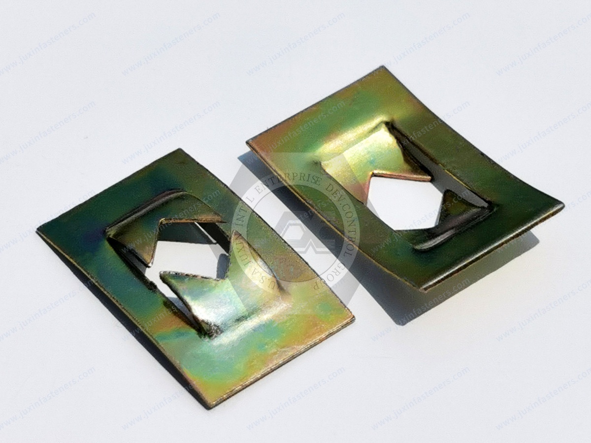
An edge-mounted clip nut is often installed before the mating screw enters the assembly.
This creates two separate positioning stages:
Stage 1: Clip installation and positioning
The spring nut must remain sufficiently located for subsequent assembly.
Stage 2: Screw engagement and joint tightening
The screw must enter the intended thread or screw-engaging feature without excessive misalignment.
If the clip geometry, hole setback or panel fit is wrong, the screw may approach the fastening feature off-center.
Possible production symptoms can include:
difficulty starting the screw;
cross-threading;
thread damage;
clip displacement;
inconsistent seating;
rework during assembly.
For automated screwdriving, alignment deserves particular attention because automation has less ability than a human operator to compensate for a poorly positioned fastener.
This distinction is essential when comparing U-nuts and J-nuts.
Clip retention describes how the clip remains located on the panel before and during assembly.
Joint strength describes the behavior of the completed fastening system under its actual service loads.
The completed joint depends on factors including:
screw specification;
thread engagement;
clip/nut geometry;
panel material;
panel thickness;
local bearing area;
clamp load;
tightening process;
tensile loading;
shear loading;
vibration or cyclic loading;
temperature;
corrosion environment.
A product description such as “Strong-Grip” should therefore not be interpreted as a universal structural, vibration, fatigue or high-load rating.
For demanding applications, the assembled joint should be validated under the actual service and installation conditions.
Carbon steel and spring-steel constructions are commonly associated with edge-mounted spring fasteners, but material designation alone does not define finished-part performance.
Material selection should consider both manufacturing requirements and service environment.
Relevant factors include:
required spring function;
forming geometry;
panel fit;
corrosion exposure;
coating system;
operating environment;
contact with dissimilar metals;
customer material specification.
If a specific material grade is mandatory, it should be stated on the drawing or RFQ rather than inferred from a generic product description.
Surface treatment is another area where generic catalog descriptions can create sourcing errors.
Carbon-steel clip-on nuts may use different protective finishes depending on product and project requirements.
Zinc-based coatings, phosphate-based finishes and other systems can have different implications for corrosion protection, friction, appearance and assembly.
The required finish should therefore be selected from the actual environment and customer specification.
Where corrosion testing is required, the RFQ should state the required test method and acceptance criteria rather than assuming a generic coating automatically provides a particular number of salt-spray hours.
OEM programs may require metric or inch fastening systems depending on the equipment platform and target market.
However, thread system is only one part of clip selection.
For either metric or inch applications, engineers should confirm:
thread designation;
thread pitch where applicable;
mating screw specification;
panel thickness;
hole size;
hole setback;
clip reach;
edge geometry;
required material;
required finish.
JUXIN FASTENERS should confirm specific size and thread availability against the requested product geometry and drawing.
This avoids assuming that every clip configuration is available across every metric or inch thread family.
Sheet-metal fabricators use edge-mounted clip nuts when an assembly needs a threaded fastening point without adding a conventional loose nut behind the panel.
Typical application areas can include:
chassis;
fabricated housings;
equipment covers;
removable panels;
brackets;
folded sheet structures;
access panels;
service covers.
The engineering advantage is highly dependent on the assembly.
Clip-on nuts can simplify certain edge-accessible designs, but they are not automatically the best fastening method for every sheet-metal joint.
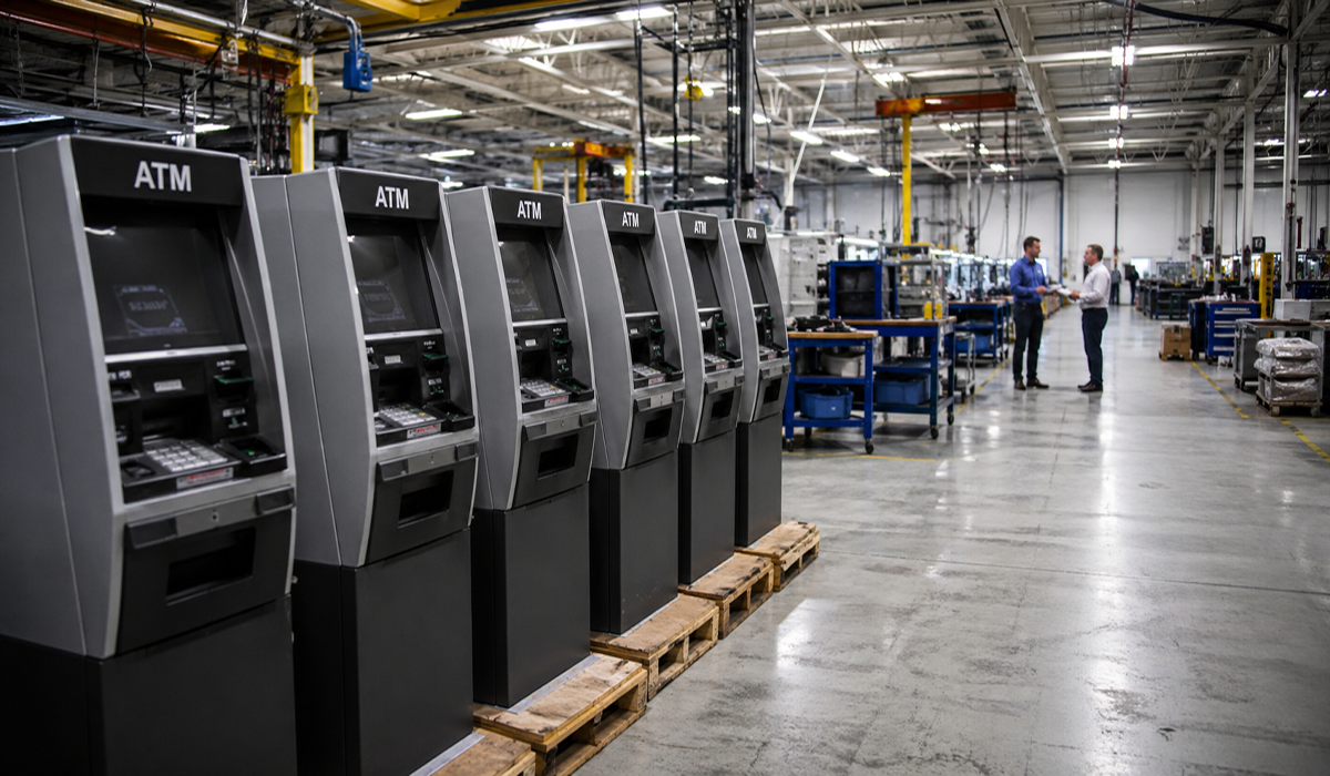
Electrical equipment frequently uses folded sheet-metal construction with access doors, covers, internal brackets and service panels.
These assemblies can create exactly the geometry questions that distinguish U-nuts from J-nuts:
Is the hole near a folded edge?
Is there room behind the flange?
Can the clip slide onto the edge after painting?
Will an internal component interfere with the clip?
Is the screw inserted from the front?
Does the service panel need to be removable?
Is the fastening location accessible during final assembly?
For this industry, choosing the clip geometry from the actual cabinet cross-section is more reliable than selecting from thread size alone.
Clip-on nuts should not automatically be treated as grounding or electrical bonding components unless the specific joint has been designed and validated for that purpose.
U-nuts, J-nuts and related spring fasteners may be considered for suitable non-structural automotive sheet-metal applications such as:
service covers;
interior mounting structures;
equipment brackets;
trim-supporting structures;
removable panels;
selected body-related sheet-metal attachments.
Automotive assemblies introduce additional requirements for packaging, production sequence, panel tolerances and service access.
Where vibration, cyclic loading, corrosion or other demanding conditions are relevant,
those requirements should be defined and validated for the complete joint rather than assumed from the clip geometry.
HVAC housings, air-handling equipment, machinery enclosures and other fabricated equipment can contain large numbers of folded sheet-metal edges and removable service panels.
For these assemblies, U-nut versus J-nut selection may be driven primarily by:
flange geometry;
panel thickness;
available edge clearance;
service access;
screw location;
production installation sequence;
corrosion environment.
Again, the fastener should be selected from the actual panel cross-section.
Information Gain is not only about explaining where a product works. It should also help engineers recognize when another fastening method may be more appropriate.
A clip-on spring nut may not be the preferred solution when:
the fastening location is too far from an accessible panel edge;
clip installation access is unavailable;
a permanently installed threaded point is required;
the design requires a fastening point away from the edge;
the panel geometry cannot retain the clip appropriately;
application-specific load or environmental requirements favor another attachment method.
Depending on the assembly, engineers may instead evaluate:
Self-clinching nuts when a permanently installed threaded fastener can be mechanically installed into suitable sheet material.
Blind rivet nuts when a threaded attachment is required through a prepared hole and installation is available primarily from one side.
Weld nuts when the manufacturing process and parent material permit a welded threaded attachment.
These fastening technologies solve different engineering problems and should not be treated as interchangeable equivalents.
A practical selection process can begin with the sheet metal rather than the fastener catalog.
Identify:
material;
nominal thickness;
thickness tolerance;
coating condition;
flat edge, folded edge or flange.
Measure:
hole diameter;
edge-to-hole-center distance;
surrounding clearance;
nearby bends and components.
Specify:
metric or inch system;
thread or screw type;
pitch where applicable;
screw length;
installation direction.
Determine whether the clip can physically slide into position during the real production sequence.
Only after the panel, hole and screw conditions are known should the engineer compare U-nut, J-nut or another clip-on geometry.
For applications with meaningful mechanical or environmental requirements, validate the complete assembly under the intended installation and service conditions.
A visually similar spring nut is not automatically interchangeable.
When evaluating an alternate supplier or consolidating part numbers, procurement and supplier-development teams should compare more than price and thread size.
Check:
overall geometry;
panel fit;
throat/reach dimension;
hole setback compatibility;
thread/screw interface;
installation direction;
material;
finish;
surrounding clearance;
packaging and handling requirements;
drawing revision;
customer-specific inspection requirements.
This is particularly important when a clip nut is already integrated into a stamped or folded sheet-metal design.
A small geometric difference can affect assembly even when the screw thread remains unchanged.
For prototype evaluation, supplier development or production sourcing, send JUXIN FASTENERS enough information to evaluate the actual panel interface.
A useful RFQ package should include:
2D drawing;
3D model if available;
reference photo or existing sample;
required U-nut, J-nut or functional geometry if already defined;
metric or inch requirement;
thread size and pitch where applicable;
mating screw specification;
panel material;
nominal panel thickness;
panel thickness tolerance;
hole diameter;
hole setback from the sheet edge;
flange or folded-edge geometry;
critical clearance dimensions;
installation direction;
material requirement;
surface treatment requirement;
environmental exposure;
application description;
prototype/sample quantity;
estimated production order quantity;
annual demand;
packaging requirements;
inspection requirements;
customer-specific specifications.
For custom or drawing-based U-nuts, J-nuts, clip-on nuts and spring fastener sourcing, contact JUXIN FASTENERS at info@juxinfasteners.com.
Providing the panel geometry together with the fastener requirements allows engineering and sourcing teams to evaluate the fastening interface more efficiently than specifying the thread size alone.
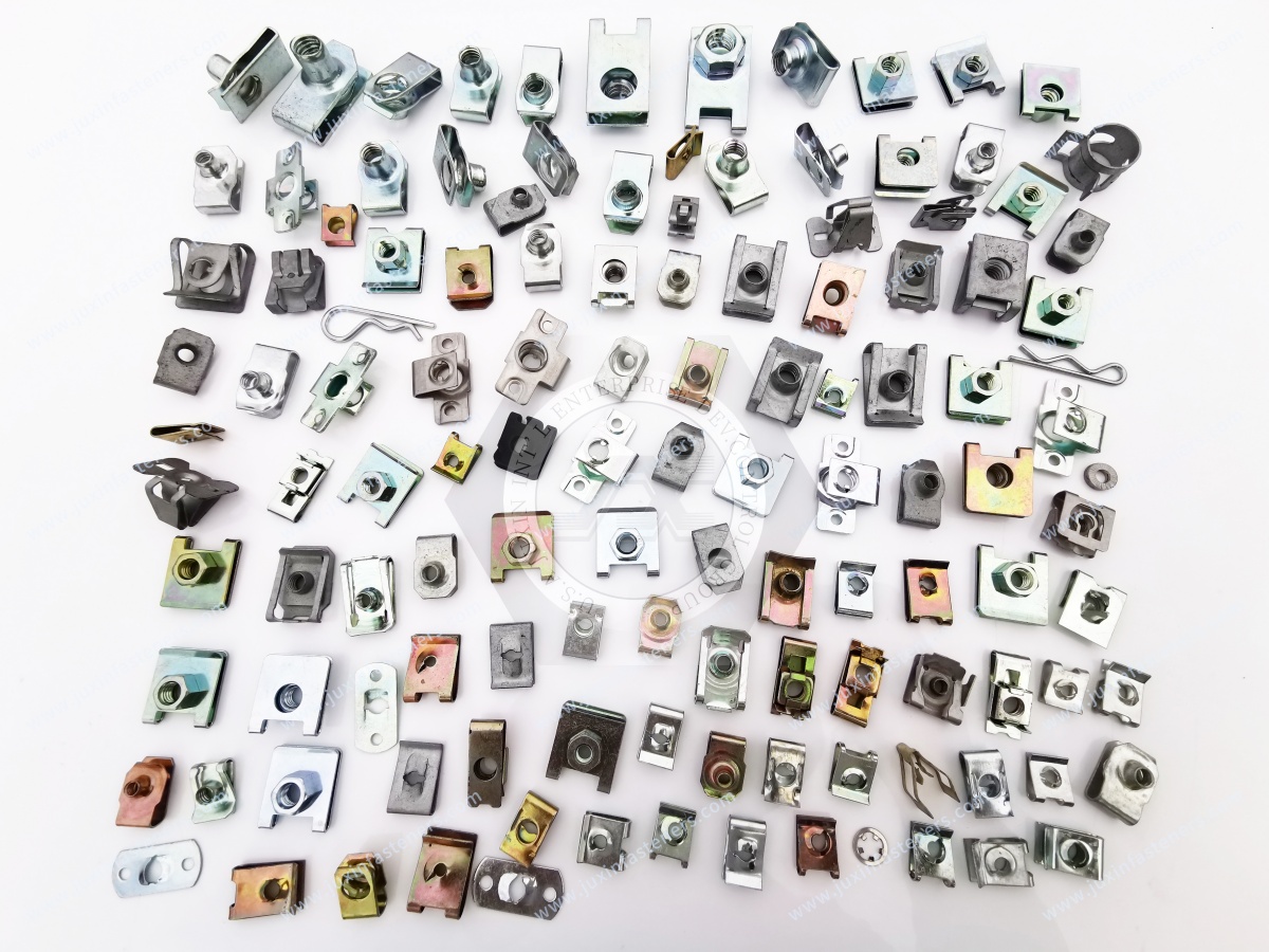
Product Packaging
Packaging Standard
At Juxin Fasteners, we apply standardized export packaging to ensure product protection, traceability, and compliance with international logistics requirements.
1. Standard Export Packaging
Unless otherwise specified, all products will be packed according to our factory standard export packaging, which includes:
Moisture-resistant inner protection
Poly bag or small box packing as required
Reinforced export cartons
Clear labeling with part number, specification, batch number, and quantity
Palletizing for sea or air shipment when necessary
Our standard packaging is designed to ensure safe transportation, efficient warehousing, and long-distance international shipping.
2. Customized Packaging Options
We also provide customized packaging solutions according to customer requirements, including but not limited to:
Private labeling
Customized barcodes
Specific carton dimensions
Retail packaging
Special pallet configuration
Customer-specific marking and identification
So that you know, customized packaging may involve additional costs and extended lead time depending on the complexity of the requirements.
3. Compliance & Quality Assurance
All packaging processes are controlled under our ISO 9001 quality management system to ensure consistency, traceability, and product integrity throughout the supply chain.
Product Pictures
Contact Us
Tel.:
+86 020 8621 0320
+86 020 3121 6067
E-mail:
Technical Support:
Navigation
SEND INQUIREY