Call Us
+86 136 6007 9809
Call Us
+86 136 6007 9809

A clip-on nut failure on an assembly line rarely begins with the clip alone.
When a U-nut, J-nut, spring nut or edge-mounted clip nut falls off the panel, shifts during screw insertion, strips during rundown,
cross-threads, fails to develop the expected clamp load or damages the sheet-metal edge, the visible symptom is only the starting point.
Product Specification
A clip-on nut failure on an assembly line rarely begins with the clip alone.
When a U-nut, J-nut, spring nut or edge-mounted clip nut falls off the panel, shifts during screw insertion, strips during rundown,
cross-threads, fails to develop the expected clamp load or damages the sheet-metal edge, the visible symptom is only the starting point.
The actual root cause may involve the interaction between:
clip geometry;
panel thickness;
flange geometry;
panel-edge condition;
mounting-hole location;
screw diameter and pitch;
thread engagement;
component alignment;
assembly-tool settings;
joint friction;
material condition;
coating thickness;
tolerance stack-up;
installation sequence.
For quality, manufacturing and design engineers, effective clip-on nut failure analysis therefore requires a joint-level diagnostic process rather than simply replacing one spring nut with another.
This guide provides a systematic engineering workflow for troubleshooting clip-on nut failures in industrial machinery, automotive and EV equipment, sheet-metal enclosures,
HVAC systems, electrical equipment, industrial automation and other high-volume sheet-metal assemblies.
Most production problems involving clip-on nuts can be grouped into several failure families:
Clip retention failure — the fastener moves or falls off the panel before final assembly.
Alignment failure — the clip thread is not correctly aligned with the screw and mating holes.
Thread failure — the screw cross-threads, strips or damages the clip thread.
Rundown failure — torque rises abnormally, becomes unstable or reaches the tool limit before proper seating.
Panel-interface failure — the panel bends, cracks, scratches or deforms around the fastener.
Joint-performance failure — the assembled joint does not maintain the required clamp condition or structural position.
Environmental or service failure — corrosion, thermal cycling, vibration or other service conditions affect the complete assembly.
The first troubleshooting rule is therefore:
Do not diagnose the component only from the final symptom.
A stripped thread, for example, can result from excessive tightening, but it can also originate from screw misalignment, incorrect pitch, insufficient engagement or dimensional interference.
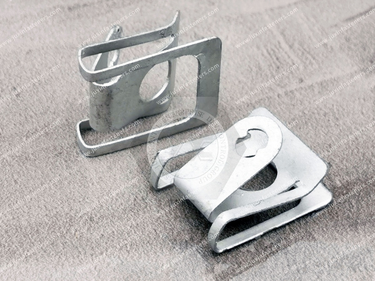
When a production issue occurs, quality teams should first document exactly what happened.
Useful observations include:
Did the clip fall off before screw installation?
Did it move during screw engagement?
Did the screw enter straight?
Did resistance increase immediately?
Did the screw rotate without developing clamp?
Did the thread strip suddenly?
Did the panel deform before the joint seated?
Did the clip fracture?
Did the joint pass assembly but fail later?
Is the problem intermittent or present on every part?
Did the failure begin after a supplier, coating, panel or tooling change?
These observations help separate the failure mode from the root cause.
The clip-on nut:
slides along the panel edge;
rotates around the edge;
falls off during material handling;
moves when the screw first contacts the thread;
becomes misaligned before final assembly.
Possible causes include:
panel thickness outside the intended grip range;
incorrect clip geometry;
insufficient spring retention for the actual panel;
flange geometry incompatible with the clip;
excessive panel-edge radius;
burrs or local deformation;
coating thickness affecting effective panel thickness;
incorrect installation depth;
excessive handling before screw assembly;
vibration during transport between assembly stations.
The diagnostic process should begin with the physical interface between the clip and panel.
This distinction is critical.
Clip retention describes the fastener's ability to remain positioned on the panel before and during assembly.
Joint strength describes the performance of the completed screw-fastener-panel system after tightening.
A clip may have excellent pre-assembly retention but still produce an inadequate final joint.
Conversely, a clip may require only moderate pre-assembly retention yet form a suitable joint after the screw is correctly installed.
Therefore:
Clip Retention ≠ Final Joint Strength
Quality specifications should avoid treating them as the same performance characteristic.
Clip-on nuts rely on controlled interaction between the spring body and the panel edge.
If the panel is thinner than the clip's intended range, retention may be inadequate.
If the panel is thicker than intended, installation may:
overstress the clip;
permanently deform the spring body;
damage the panel finish;
alter hole alignment;
make assembly difficult.
For detailed engineering guidance, see Panel Thickness Selection Guide.
A drawing may state a nominal sheet thickness, but the production interface can also be influenced by:
material tolerance;
coating thickness;
paint;
powder coating;
plating;
stacked layers;
hemmed edges;
local forming;
panel distortion.
Therefore, failure analysis should evaluate the actual finished interface, not only the nominal raw sheet thickness.
One of the most important clip-on nut failure mechanisms is geometric misalignment.
A typical assembly may contain:
Panel Hole → Clip Thread → Mating Component Hole → Screw
These features must align sufficiently for the screw to enter the thread without excessive side loading.
If they do not, the screw may:
contact the side of the clearance hole;
push the clip sideways;
enter the thread at an angle;
cross-thread;
damage the formed thread;
create abnormal rundown torque.
For edge-mounted clip nuts, the distance between the panel edge and the mounting hole directly affects thread alignment.
This dimension is often called:
Hole Setback
or:
Edge-to-Hole Distance
The clip geometry must position its threaded feature at the same location as the panel hole.
Therefore:
Correct Thread Size + Wrong Hole Setback = Wrong Fastener
This is one of the most common reasons a visually similar replacement clip fails in production.
A screw may appear capable of entering the clip even when the centers are not correctly aligned.
During powered rundown, however, the screw can force the clip sideways.
This creates lateral loading on the thread interface.
Possible results include:
cross-threading;
partial thread engagement;
localized thread deformation;
elevated torque;
inconsistent clamp development.
A replacement clip should therefore be validated against the actual panel geometry rather than selected from appearance alone.
Cross-threading occurs when the mating screw does not correctly follow the intended thread path.
Potential causes include:
incorrect screw pitch;
incompatible thread form;
angular screw entry;
hole misalignment;
damaged screw threads;
damaged clip threads;
clip movement during engagement;
excessive driver speed before proper thread engagement.
A cross-threaded joint can produce deceptively high torque without developing the intended clamp condition.
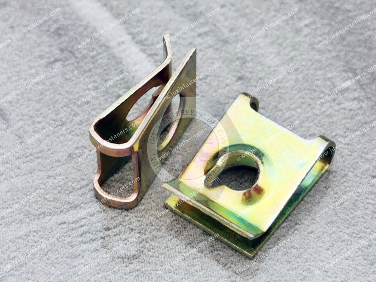
This is one of the most important troubleshooting principles in threaded assembly.
The assembly tool measures or controls torque.
But the engineering objective is usually an appropriate joint clamp condition.
Torque is influenced by friction and thread interaction.
Abnormal friction caused by:
cross-threading;
damaged threads;
coating variation;
interference;
misalignment;
contamination
can increase torque before the joint is properly seated.
Therefore:
High Rundown Torque ≠ High Clamp Load
A torque-controlled tool can report an apparently successful cycle even when the underlying joint is abnormal unless the assembly process is appropriately validated.
Screw continues rotating without further tightening.
Clamp cannot be achieved.
Metal fragments appear around the thread.
Clip thread visibly deforms.
Screw can be removed with damaged mating threads.
Thread stripping can result from:
excessive tightening;
incorrect screw diameter;
wrong thread pitch;
insufficient thread engagement;
thread misalignment;
damaged threads;
unsuitable screw/clip combination;
material or heat-treatment variation;
repeated assembly beyond the validated design requirement.
The stripped component should be inspected before assigning the root cause.
Some spring-nut architectures use formed or limited thread engagement rather than the deeper thread engagement associated with conventional full nuts.
SAE J891 covers recognized metric and inch spring-nut configurations intended for general applications where single-thread engagement with the mating screw can be adequate for the intended application.
This does not mean every clip-on nut has only one engaged thread.
It does mean engineers should not automatically apply assumptions from a conventional hex nut to a spring-nut architecture.
The actual product geometry and mating screw must be evaluated together.
For any clip-on nut, confirm:
nominal screw diameter;
thread pitch;
thread form;
screw material/property requirements where relevant;
screw tip geometry where relevant;
required engagement;
assembly method.
A screw that can physically enter the fastener is not necessarily the correct mating screw.
Metric and inch fasteners can sometimes appear dimensionally similar.
This is particularly dangerous in production troubleshooting.
A screw may begin to engage an incompatible spring nut but damage the thread during rundown.
When investigating stripping or inconsistent torque, verify the actual screw specification rather than relying on visual identification.
For selection guidance, see Metric Clip-On Nuts Selection Guide and Inch Clip-On Nuts Selection Guide.
This symptom can indicate several different conditions.
Potential causes include:
stripped clip thread;
damaged screw thread;
insufficient engagement;
clip deformation;
wrong screw;
incorrect clip geometry;
thread feature rotation or deformation in the specific fastener design.
Do not automatically assume the clip is “loose.”
Inspect both mating components.
A clip may remain attached during handling but shift once the screw contacts it.
Potential causes include:
insufficient panel retention;
hole misalignment;
excessive initial screw side load;
incorrect clip setback;
driver angle;
poor mating-part alignment.
This symptom strongly suggests that the diagnostic team should evaluate both clip retention and assembly alignment.
flange bends;
coating cracks;
panel surface marks;
local indentation;
edge deformation;
clip cannot seat completely.
Possible causes include:
clip grip range incompatible with panel thickness;
excessive installation force;
spring geometry unsuitable for the flange;
thin or low-stiffness panel;
local forming around the mounting location;
sharp clip contact geometry;
installation over a coated surface without sufficient allowance.
The solution may involve changing the clip, the panel or both.
A fractured spring clip should trigger a broader investigation.
Potential contributors can include:
excessive installation deformation;
unsuitable material condition;
manufacturing defect;
aggressive forming radius;
excessive panel thickness;
environmental degradation;
repeated installation/removal;
service overload.
A fracture should not automatically be attributed to “insufficient hardness.”
Spring-component performance depends on the complete material and manufacturing condition.
For spring fasteners, increasing hardness without considering forming and toughness can create new failure risks.
The required behavior is a balance of:
elastic recovery;
strength;
toughness;
formability;
fatigue behavior where relevant.
Therefore:
Higher Hardness ≠ Automatically Better Clip Performance
Material and heat-treatment requirements should follow the applicable drawing, product specification and validated performance requirement.
Clip-on fasteners can contact painted, plated or powder-coated panels during installation.
Potential issues include:
scratching;
coating removal;
local cracking;
altered effective panel thickness;
friction changes.
The acceptable condition depends on the application.
For corrosion-sensitive assemblies, the interface between fastener, panel material and coating system should be evaluated as a system.
Corrosion can affect:
clip section;
panel surface;
serviceability;
removal;
long-term interface condition.
Potential factors include:
moisture;
salt exposure;
condensation;
chemicals;
dissimilar materials;
damaged coatings.
A coating name alone does not establish service life.
Corrosion protection should be selected for the actual environment and customer requirement.
If a screw-fastened assembly loosens during operation, do not immediately blame the clip's spring legs.
Possible causes include:
insufficient initial clamp;
joint settlement;
vibration;
transverse movement;
thermal cycling;
friction variation;
inadequate locking strategy;
structural flexibility.
The clip's pre-assembly retention function and the final joint's resistance to loosening are different engineering problems.
Some clip-on fasteners provide useful retention and may perform reliably in vibrating equipment.
However, the phrase:
“Spring Clip = Vibration-Proof Joint”
is too broad.
Resistance to service loosening depends on the complete joint architecture.
Where vibration is a major design condition, engineers should evaluate the actual locking strategy and joint validation requirements.
See Strong-Grip Clip-On Nuts for Vibration-Resistant Assemblies for application-specific selection considerations.
A production line may report wide variation in rundown torque even when no obvious component is broken.
Potential contributors include:
screw coating variation;
clip thread variation;
panel misalignment;
driver-angle variation;
contamination;
damaged screws;
thread-form mismatch;
changing assembly speed;
inconsistent seating condition.
Torque variation should therefore be investigated as a system response.
For automated assembly lines, torque-angle curves can provide useful diagnostic information.
The exact signature depends on the joint, but engineers can compare known-good and failed assemblies for differences in:
thread engagement;
seating point;
torque rise;
angular displacement;
final rundown behavior.
The purpose is not to apply one universal torque-angle curve.
It is to identify abnormal assembly behavior relative to a validated baseline.
A powerful failure-analysis technique is to preserve data from validated assemblies.
The baseline may include:
approved clip;
approved screw;
controlled panel;
actual panel thickness;
hole location;
installation force;
rundown parameters;
torque-angle trace where available;
final assembly inspection.
When a failure appears, compare it against this known-good condition.
| Observed Symptom | Possible Root Causes | First Checks |
|---|---|---|
| Clip falls off panel | Wrong grip range, insufficient retention, flange mismatch | Panel thickness, clip geometry, installation depth |
| Clip shifts during screw entry | Misalignment, insufficient retention, wrong setback | Hole centers, setback, driver angle |
| Screw will not start | Wrong thread, misalignment, damaged thread | Screw specification, clip thread, hole alignment |
| Cross-threading | Angular entry, pitch mismatch, clip movement | Screw angle, pitch, alignment |
| High torque before seating | Misalignment, interference, thread damage, friction | Torque-angle trace, threads, holes |
| Screw spins without clamp | Stripped thread, damaged screw, insufficient engagement | Clip thread, screw thread, engagement |
| Panel bends | Wrong grip range, excessive force, weak flange | Panel thickness, clip geometry |
| Clip fractures | Over-deformation, material/process issue, overload | Failed surface, grip range, installation method |
| Joint loosens in service | Insufficient preload, settlement, vibration, thermal cycling | Complete joint, not only clip |
| Corrosion develops | Environment, coating damage, material interaction | Finish, panel material, exposure |
When a production line is affected, teams often need two parallel actions.
Possible actions include:
segregating suspect lots;
increasing inspection;
verifying panel thickness;
checking screw specification;
checking tool setup;
replacing visibly damaged components.
Containment protects production.
It does not establish the root cause.
The permanent solution may require:
different grip range;
revised hole setback;
different clip geometry;
corrected screw;
revised rundown parameters;
improved panel tolerance;
material/process correction;
supplier process correction.
Do not confuse temporary containment with permanent corrective action.
Do not immediately discard or modify them.
Keep:
failed clip;
mating screw;
panel section;
mating component.
Document:
clip position;
screw angle;
panel deformation;
hole alignment;
fracture location.
Identify:
clip lot;
screw lot;
panel lot;
coating lot where relevant;
assembly station;
date/time;
tool identification.
Check:
thickness;
coating;
flange geometry;
edge condition;
hole size;
hole setback.
Check:
diameter;
pitch;
thread condition;
length;
tip;
head style;
specification.
Check:
profile;
thread feature;
free geometry;
contact surfaces;
coating;
fracture or deformation.
Compare:
panel hole;
clip thread;
mating-part hole;
driver axis.
Where available, compare:
tool program;
torque;
angle;
speed;
failed cycles;
known-good cycles.
Controlled reproduction is more valuable than speculation.
Change one variable at a time where practical.
Do not release a change solely because a small number of samples assembled successfully.
Use the customer's required validation plan.
When troubleshooting, changing the:
clip;
screw;
panel;
tool torque;
driver speed
all at once may make the problem disappear without identifying why.
A controlled A/B comparison is often more informative.
For example:
Current Clip + Current Panel + Current Screw
versus:
Candidate Clip + Current Panel + Current Screw
Then change the next variable only if required.
This makes corrective-action evidence more useful.
Problems sometimes appear after changing clip-on nut suppliers even when the new component has the same nominal:
thread size;
panel range;
overall dimensions.
Possible hidden differences include:
spring geometry;
hole setback;
thread-form geometry;
material condition;
coating thickness;
free-state dimensions;
manufacturing tolerances.
Therefore:
Same Catalogue Description ≠ Automatically Same Assembly Behavior
Supplier transitions should be validated against the actual joint.
A buyer may measure only:
M6 Thread
or:
1.0 mm Panel
and assume this defines the fastener.
It does not.
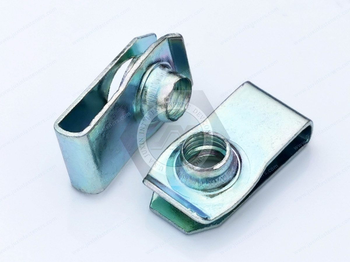
A clip-on nut is a multi-interface component.
Important variables can include:
thread;
grip range;
throat depth;
hole setback;
overall width;
overall length;
free opening;
clip profile.
For geometry selection, see Clip-On Nuts, U-Nuts & J-Nuts Selection Guide.
When threads are damaged, inspect both mating components.
Possible conditions include:
Potential causes may include clip geometry, material condition, insufficient engagement or excessive assembly demand.
The screw may have incompatible or damaged threads.
This can indicate severe cross-threading, incompatible thread forms or overload.
Failure analysis should identify the actual damaged interface.
The torque at which a clip-nut assembly strips depends on the actual combination of:
clip;
screw;
thread;
material;
finish;
engagement;
alignment;
test method.
Do not copy a strip-torque value from an unrelated product and apply it to another clip.
For OEM programs, validate the actual production combination.
A torque value should not be assigned simply because a screw diameter is known.
Appropriate tightening depends on the complete assembly.
Relevant variables can include:
screw specification;
fastener geometry;
friction;
joint material;
desired clamp condition;
service requirement.
Use customer-approved or validated assembly parameters.
ISO 2320 specifies functional properties for particular prevailing-torque steel nuts within its defined scope.
It should not automatically be applied to every clip-on nut, U-nut or spring nut.
Clip-on fastener qualification should instead follow the applicable product standard, customer drawing and validated assembly requirements.
SAE J891 provides recognized metric and inch spring-nut configurations for general-use applications.
It also recognizes that spring nuts can exist in other configurations and that application-specific requirements may require manufacturer involvement.
This is important for OEM sourcing because many commercial clip-on nuts are application-driven components.
A standard reference is useful, but the actual joint geometry still controls product selection.
For international OEM programs, material requirements should be expressed using the applicable:
drawing;
product standard;
recognized material specification;
approved supplier specification.
Avoid assuming regional material grades are exact substitutes without technical comparison.
Carbon spring steel is widely used in clip-on fasteners because properly processed spring material can provide the elastic recovery required for edge retention.
However, performance depends on:
grade;
thickness;
forming;
heat treatment;
final geometry.
Material name alone does not establish clip performance.
Stainless spring materials may be considered where corrosion resistance is required.
However:
Stainless ≠ Corrosion-Proof
and:
Stainless ≠ Automatic Drop-In Replacement for Carbon Spring Steel
Spring behavior, geometry, strength, forming characteristics and environmental requirements must be evaluated.
Surface finish can affect:
corrosion resistance;
dimensions;
friction;
appearance;
electrical interface where relevant.
For close-fitting spring clips, coating thickness can also influence the effective panel interface.
Finish requirements should therefore be part of the controlled product specification.
Industrial machinery may use clip-on nuts for:
guards;
covers;
service panels;
access doors;
sheet-metal enclosures.
Common troubleshooting concerns include:
vibration;
repeated service access;
panel alignment;
field replacement;
mixed hardware.
For machinery-specific applications, see Industrial Machinery Guard Clips.
Potential clip-on nut applications include:
body panels;
brackets;
underbody shields;
interior structures;
auxiliary enclosures;
service covers;
thermal-management assemblies.
Automotive troubleshooting often requires careful control of:
panel stack-up;
hole position;
coatings;
automated screwdriving;
supplier variation.
Safety-critical applications require the applicable customer specification and validation.
Clip-on nuts can simplify assembly of:
cabinet panels;
covers;
access doors;
brackets.
Failure analysis should consider:
sheet thickness;
coating;
electrical requirements;
service access.
Do not assume a clip-on nut automatically provides a compliant grounding path.
Potential mechanical applications include:
server and rack enclosures;
power-distribution cabinets;
cooling-equipment panels;
fan assemblies;
service covers.
Clip-on fasteners can support efficient sheet-metal assembly, but the application still requires appropriate mechanical validation.
Potential uses include:
fan housings;
equipment covers;
control enclosures;
brackets;
service panels.
Clip-on nuts do not automatically create airtight or watertight joints.
Sealing must be addressed separately.
Automated machinery frequently contains:
sheet-metal guarding;
sensor brackets;
control cabinets;
covers;
access panels.
Where automated screwdriving is used, alignment and rundown consistency become especially important.
When a clip-on nut issue reaches a quality meeting, the team should be able to answer:
What exactly failed?
When did it fail?
Which component failed first?
Did the clip remain on the panel?
Was the screw aligned?
Was the correct screw used?
Was the actual panel thickness measured?
Was hole setback verified?
Were the threads inspected?
Was torque-angle data reviewed?
Did the problem follow a supplier or process change?
Can the failure be reproduced?
If these questions cannot be answered, the investigation is not yet complete.
Once engineering identifies the failure mechanism, procurement can source the replacement more accurately.
For example:
Instead of:
“Current U-nut is bad. Find another M6 U-nut.”
the requirement may become:
“M6 clip-on nut for finished panel thickness X–Y, required hole setback Z, current failure is clip migration during screw engagement,
mating screw specification attached, annual volume 300,000 pcs.”
That is a much stronger supplier-development request.
For engineering review by JUXIN FASTENERS, provide where available:
current clip-on nut drawing;
current supplier part number;
photographs;
failed samples;
panel drawing;
mating-component drawing;
actual finished panel thickness;
panel material;
panel coating;
hole diameter;
hole setback;
flange geometry;
screw diameter;
screw pitch;
screw length;
screw specification;
screw coating;
assembly-tool type;
driver speed where relevant;
torque setting;
torque-angle data where available;
failure frequency;
failure stage;
production quantity;
annual demand;
service environment;
corrosion requirement;
dimensional requirements;
inspection requirements;
packaging requirements.
Common causes include incorrect grip range, incompatible clip geometry, insufficient retention, panel-edge variation or incomplete installation.
Possible causes include insufficient panel retention, screw misalignment, incorrect hole setback or angular driver entry.
Potential causes include excessive assembly demand, wrong screw pitch or diameter, misalignment, damaged threads or insufficient engagement.
Misalignment, cross-threading, interference, thread damage or friction can increase torque before proper seating.
Not necessarily. Abnormal friction or thread interference can produce high torque without the intended clamp condition.
Yes. The clip geometry must match the actual finished panel interface and intended grip range.
Hole setback determines whether the clip's threaded feature aligns with the panel hole and mating component.
Not automatically. Grip range, setback, geometry, material condition, finish and tolerances may differ.
Not generically. ISO 2320 applies to prevailing-torque steel nuts within its defined scope and should not automatically be applied to clip-on spring nuts.
Yes. SAE J891 covers recognized metric and inch spring-nut configurations for general use, but the actual assembly requirements still need to be verified.
Not automatically. Service loosening depends on the complete joint, preload, movement, friction, thermal conditions and locking strategy.
JUXIN FASTENERS can review the available drawing, panel dimensions, mating screw, failed samples,
assembly information and production requirements to help identify an appropriate clip-on nut configuration for evaluation.
A production problem may begin with:
“Our U-nuts keep stripping.”
That is a symptom.
The engineering process should convert it into:
Failure Symptom → Failed Interface → Panel Geometry → Hole Alignment → Screw Compatibility → Rundown Behavior → Material / Geometry Review → Root Cause → Corrective Candidate → Validation
The commercial process then becomes:
Failure Analysis → Engineering Review → Candidate Clip → Samples → Assembly Validation → Approved Specification → Production RFQ
This is far more reliable than replacing one visually similar clip with another.
JUXIN FASTENERS supports OEM and industrial sourcing for:
clip-on nuts;
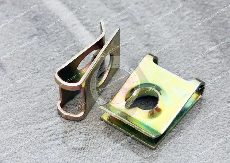
U-nuts;
J-nuts;
spring nuts;
spring-steel clip nuts;
enclosed hex clip-on nuts;
tapping-screw clip nuts;
metric clip-on nuts;
inch clip-on nuts;
drawing-based spring fasteners.
For related engineering guidance, see:
Panel Thickness Selection Guide
Clip-On Nuts, U-Nuts & J-Nuts Selection Guide
Strong-Grip Clip-On Nuts for Vibration-Resistant Assemblies
Strong-Grip Clip-On Nuts for Tapping Screws
Strong-Grip Clip-On Enclosed Hex Nuts
Carbon Steel Clip-On Nuts: Material & Coating Guide
Metric Clip-On Nuts Selection Guide
Inch Clip-On Nuts Selection Guide
For a clip-on nut failure review or OEM sourcing project, send the available failed-part photographs, samples, drawings, finished panel thickness,
hole setback, mating screw specification, assembly parameters, required quantity and estimated annual demand to:
A successful clip-on nut failure investigation should not end with:
“Replace the failed clip.”
It should answer:
“Why did the joint fail, which interface caused the failure, and what engineering control prevents the same failure from returning to production?”
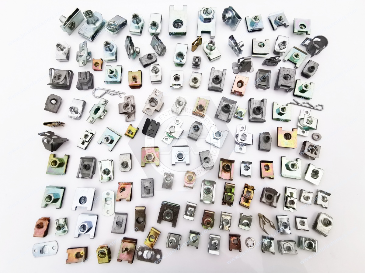
Product Packaging
Packaging Standard
At Juxin Fasteners, we apply standardized export packaging to ensure product protection, traceability, and compliance with international logistics requirements.
1. Standard Export Packaging
Unless otherwise specified, all products will be packed according to our factory standard export packaging, which includes:
Moisture-resistant inner protection
Poly bag or small box packing as required
Reinforced export cartons
Clear labeling with part number, specification, batch number, and quantity
Palletizing for sea or air shipment when necessary
Our standard packaging is designed to ensure safe transportation, efficient warehousing, and long-distance international shipping.
2. Customized Packaging Options
We also provide customized packaging solutions according to customer requirements, including but not limited to:
Private labeling
Customized barcodes
Specific carton dimensions
Retail packaging
Special pallet configuration
Customer-specific marking and identification
So that you know, customized packaging may involve additional costs and extended lead time depending on the complexity of the requirements.
3. Compliance & Quality Assurance
All packaging processes are controlled under our ISO 9001 quality management system to ensure consistency, traceability, and product integrity throughout the supply chain.
Product Pictures
Contact Us
Tel.:
+86 020 8621 0320
+86 020 3121 6067
E-mail:
Technical Support:
Navigation
SEND INQUIREY