Call Us
+86 136 6007 9809
Call Us
+86 136 6007 9809

Product Specification
What are the key engineering characteristics of DIN 32501 projection weld studs?
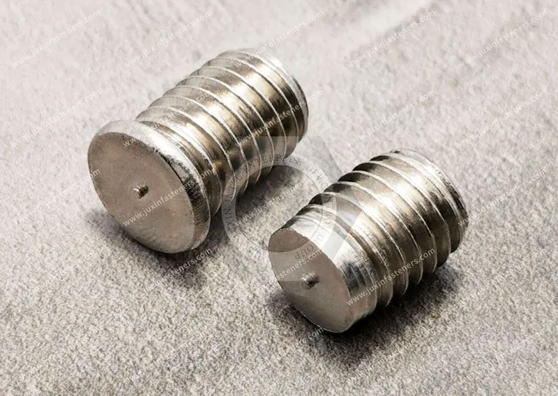
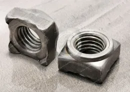
DIN 32501 projection weld studs are specialized welded fastening components designed for integration with sheet-metal assemblies.
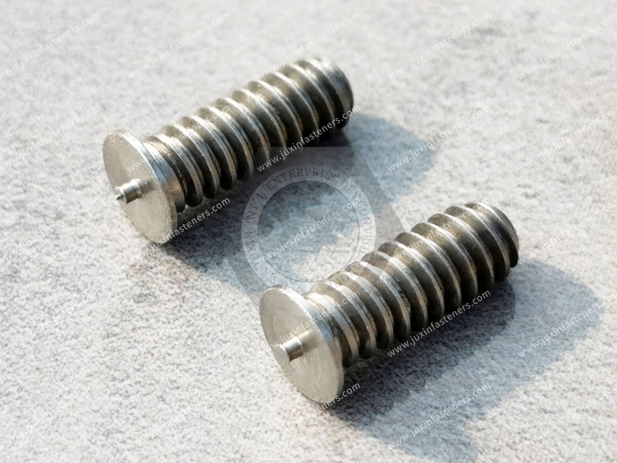
Depending on the specific configuration, the fastener can incorporate a threaded shaft together with a formed head, collar, or projection feature that assists positioning and resistance welding to the parent sheet.
A typical configuration can be represented conceptually as:
                [ Threaded Shaft ]
                       ||
                       ||
               +-------++-------+
               | Welding Head   |
               | / Collar /     |
               | Projection     |
               +-------++-------+
                       ||
=======================||=======================  Parent Sheet
                    Weld Interface
In configurations designed around a locating collar or through-hole installation, the collar or locating feature can engage with a prepared opening in the parent sheet to help establish fastener position before welding.
During resistance projection welding, electrical current passes through the fastener and parent sheet while electrode force maintains controlled contact.
Localized electrical resistance generates heat, allowing the intended projection or weld interface to soften, collapse, and develop a fusion weld nugget.
The basic heat-generation relationship is commonly expressed as:
Q = I²Rt
where current, electrical resistance, and effective welding time all influence the heat generated at the interface.
The actual weld result depends on considerably more than the equation itself. Important variables include:
Fastener material
Parent-sheet material
Sheet thickness
Projection or collar geometry
Hole geometry where applicable
Electrode force
Welding current
Welding time
Surface condition
Electrode configuration
Electrical contact resistance
Welding sequence
Equipment capability
Therefore, the welding parameters for a DIN 32501-type projection weld stud should be established for the actual fastener, substrate, equipment, and application rather than treated as universal values.
Automotive and industrial manufacturers may use welded studs where a permanent threaded attachment point is desirable and where the welding process can be integrated into the sheet-metal manufacturing sequence.
Potential applications include:
Automotive body-in-white components
Chassis-related sheet-metal structures
Brackets and reinforcement panels
Electrical cabinets
Industrial equipment
HVAC equipment
Sheet-metal enclosures
Cable and component mounting points
Other fabricated metal assemblies requiring an integrated threaded attachment
The manufacturing objective is not simply to create a stronger threaded component.
The objective is to create a repeatable fastener-to-sheet interface that works with the customer's forming, welding, coating, assembly, inspection, and supply-chain processes.
JUXIN FASTENERS can support OEM sourcing and engineering review by evaluating the fastener geometry, parent material,
welding process, surface treatment, application requirements, quality requirements, and production volume together.
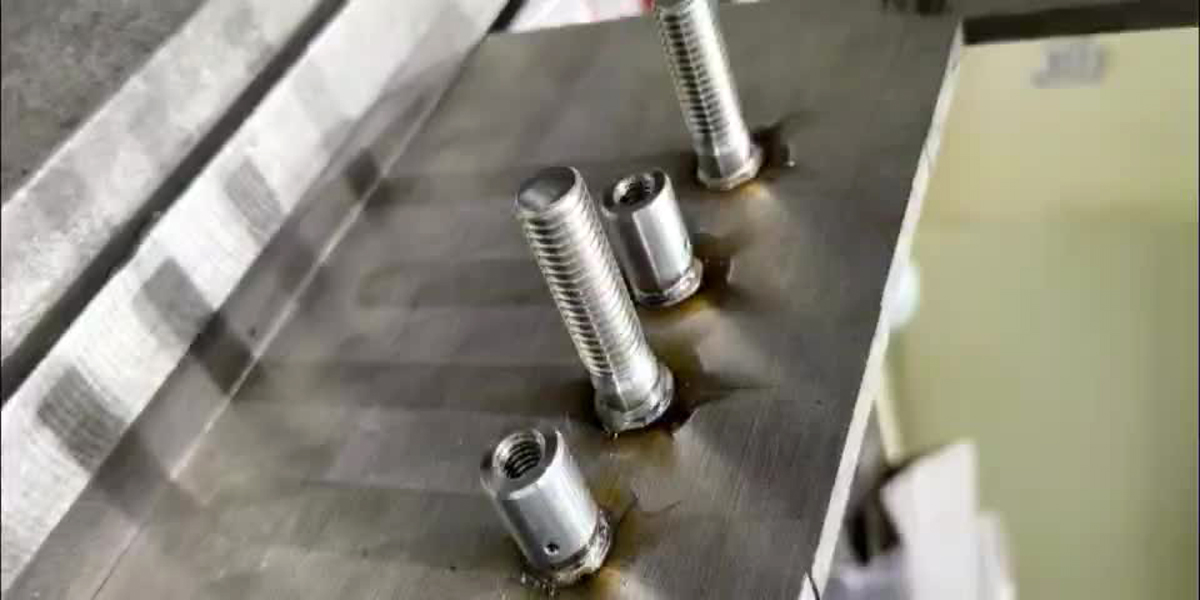
Where a specific DIN 32501 configuration incorporates a locating collar or through-hole feature, the parent sheet may be prepared with a corresponding hole.
The basic installation sequence can involve:
Preparing the specified sheet-metal hole
Positioning the stud using the locating feature
Bringing the electrode system into contact
Applying the required electrode force
Passing controlled welding current
Developing the intended weld interface
Allowing the weld to solidify under controlled conditions
Inspecting the finished attachment
The exact sequence depends on the fastener configuration and resistance-welding equipment.
The parent-sheet opening must be compatible with the locating feature of the fastener.
The relationship between:
Collar diameter
Hole diameter
Hole tolerance
Sheet thickness
Fastener position
Welding-electrode geometry
can influence the quality and repeatability of the final assembly.
The original concept of making the hole “slightly larger than the nominal stud diameter” is useful as a general design principle,
but the actual clearance should come from the specific fastener drawing, standard configuration, and welding process.
Excessive radial clearance can affect:
Fastener positioning
Concentricity
Local contact conditions
Weld alignment
Insufficient clearance can create:
Difficult insertion
Assembly interference
Fastener damage
Inconsistent positioning
For OEM production, the hole should therefore be specified together with the fastener's actual locating geometry rather than relying on a generic clearance rule.
A locating collar can serve several functions depending on the fastener design.
It may assist with:
Fastener positioning
Hole location
Orientation
Assembly repeatability
Resistance to lateral movement during handling
Establishing the intended weld interface
However, the collar should not automatically be described as a structural load-bearing feature.
Its mechanical contribution depends on the actual geometry and load path.
The engineering drawing should distinguish between:
Locating Function
and
Structural/Welded Load-Transfer Function.
This distinction becomes especially important when the stud is used in a structural or fatigue-sensitive assembly.
Resistance projection welding uses electrical current and controlled contact resistance to generate localized heat.
The simplified relationship is:
Q = I²Rt
The projection or intended contact feature concentrates current into a controlled region.
As heat develops, the projection can collapse under electrode force and the local materials can fuse.
The objective is to establish a repeatable weld interface without unnecessarily overheating the surrounding sheet.
Projection collapse is a critical part of the welding process.
The projection must be compatible with:
Fastener geometry
Parent-sheet thickness
Material properties
Electrode force
Welding current
Welding time
If the projection collapses inadequately, the weld interface may not develop as intended.
If it collapses too aggressively or the thermal input becomes excessive, the process may produce:
Expulsion
Spatter
Excessive indentation
Local sheet distortion
Electrode contamination
Therefore, projection geometry and welding parameters should be developed together.
The thermal cycle affects both the weld interface and the surrounding materials.
Potential engineering concerns include:
Heat-affected regions
Local sheet deformation
Changes in material properties
Coating breakdown
Electrode contamination
Thread-area thermal exposure
The statement that excessive heat will necessarily “degrade the mechanical strength of the threaded shaft” is too broad.
The actual thermal effect depends on:
Fastener material
Geometry
Distance between thread and weld interface
Welding energy
Welding duration
Heat dissipation
Number of welding cycles
For this reason, thermal effects should be evaluated for the actual configuration.
Projection weld studs can be incorporated into automotive body-in-white assemblies where a permanent threaded attachment point is required.
Potential applications include:
Bracket attachment
Reinforcement structures
Interior mounting points
Cable and harness attachment
Instrument-panel structures
Door-related assemblies
Seat-related components
Other sheet-metal attachment locations
The specific application determines whether the stud is a structural or non-structural component.
Not every BIW weld stud carries primary structural loads.
Welded studs may also be used in selected chassis or chassis-adjacent applications.
Where dynamic loads are present, the design team should evaluate:
Tensile loading
Shear loading
Bending
Installation torque
Vibration
Fatigue
Shock
Parent-sheet deformation
Weld-interface fatigue
The welded attachment should be considered as a complete joint.
A high-strength threaded shaft does not automatically mean that the completed sheet-metal joint has high fatigue capacity.
The weakest failure path may be:
The weld interface
The parent sheet
The stud
The surrounding panel
The mating component
The bolt/nut connection
The original Gemini text referred to “Body-in-Water.”
The correct automotive term is:
Body-in-White (BIW).
Body-in-White refers to the vehicle body structure before downstream painting and final assembly operations.
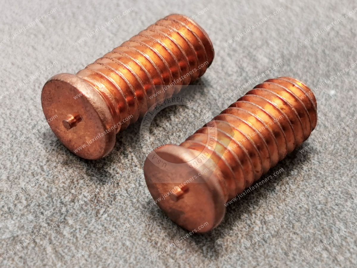
Depending on the specific product design, weld studs can incorporate different head or flange configurations.
Potential considerations include:
Flat head geometry
Flanged head geometry
Locating collar
Formed projection features
Application-specific head profiles
Custom geometries
The geometry should be selected according to:
Welding method
Panel geometry
Load path
Assembly clearance
Electrode access
Surface requirements
Manufacturing sequence
A head should not be described as “flush” or “countersunk” merely because such a geometry is possible. The actual product drawing determines whether that configuration is available and appropriate.
For automated sheet-metal production, fastener position can be important because the welded stud becomes part of the downstream assembly reference.
Position accuracy may influence:
Bracket fit
Hole alignment
Thread access
Robotic assembly
Component clearance
Cable routing
Final dimensional stack-up
Position control therefore needs to be evaluated at both:
Fastener manufacturing level
and
Panel manufacturing level.
A dimensionally consistent stud cannot compensate for a poorly controlled parent-sheet hole or panel location.
The original Gemini article specifically referenced 6 mm fastening specifications.
A 6 mm nominal size can be relevant to particular weld-stud designs and automotive applications, but it should not be presented as the defining or universally preferred size of DIN 32501 projection weld studs.
Fastener selection should instead begin with:
Required thread size
Load requirement
Available assembly space
Parent-sheet thickness
Welding equipment
Mating component
Application standard
Customer drawing
A medium-sized threaded attachment can sometimes provide an appropriate balance between installation space and mechanical capability, but the optimum size remains application-specific.
The important distinction is:
Nominal diameter is a design input, not a guarantee of structural performance.
The weld stud material should be selected according to:
Required mechanical properties
Weldability
Parent-sheet material
Corrosion environment
Surface treatment
Welding process
Application temperature
Customer specification
Low-carbon weldable steels are common in resistance-welded sheet-metal applications, but the exact material should be defined by the product drawing or engineering specification.
Potential parent materials include:
Low-carbon steel
Coated steel
Stainless steel
Higher-strength automotive steels
Other weldable sheet materials
Each material can alter the electrical and thermal characteristics of the welding interface.
Advanced high-strength steels and other higher-strength sheet materials may require particular attention to:
Welding heat input
Metallurgical response
Local deformation
Electrode force
Weld-interface development
Fatigue behavior
The fastener should therefore be validated against the actual sheet material rather than assuming that a weld-stud design suitable for mild steel will automatically perform identically on a higher-strength substrate.
Dissimilar fastener-to-sheet combinations may sometimes be technically feasible.
However, they require evaluation of:
Electrical resistance
Thermal conductivity
Metallurgical compatibility
Galvanic corrosion
Coating behavior
Mechanical performance
“Compatible” should not be interpreted as “drop-in interchangeable.”
Automotive components can experience:
Road vibration
Engine-related vibration
Repeated thermal cycling
Shock
Assembly-induced loads
Continuous cyclic loading
The weld stud therefore needs to be evaluated as part of the joint.
The original Gemini statement that permanent fusion “enhances the anti-fatigue capabilities” is too absolute.
A welded attachment can provide a reliable permanent connection, but fatigue performance depends on:
Weld geometry
Nugget size and quality
Parent-sheet thickness
Local stress concentration
Stud geometry
Loading direction
Welding process
Surface condition
Number of load cycles
Environmental conditions
For fatigue-sensitive applications, representative testing is preferable to assuming performance from fastener tensile properties alone.
The weld attachment and the mating threaded connection represent two separate engineering interfaces.
The weld must resist the loads transferred into the sheet.
The threaded joint must maintain the required clamping and assembly performance.
These should not be treated as one identical failure mechanism.
Not every weld stud configuration uses the same installation geometry.
The actual product may be designed for:
Through-hole positioning
Surface contact
Flange projection welding
Locating-collar engagement
Other application-specific resistance-welding configurations
Therefore, the OEM drawing should clearly define:
Hole requirement
Weld surface
Projection location
Fastener orientation
Electrode access
Critical dimensions
This prevents the common sourcing mistake of selecting a weld stud by thread size while overlooking the actual welding interface.
Welding current directly affects electrical heat generation.
Because:
Q = I²Rt
changes in current can produce a significant change in heat input.
However, higher current does not automatically mean higher joint strength.
Excessive current can result in:
Expulsion
Spatter
Excessive indentation
Local overheating
Electrode contamination
Insufficient current can result in:
Incomplete fusion
Inadequate projection collapse
Poor weld development
Increased process variation
Electrode force affects:
Initial contact
Projection collapse
Contact resistance
Weld-interface formation
Sheet deformation
The appropriate force must be developed for the actual stud, sheet, electrode, and welding equipment.
Welding time affects the thermal cycle and weld development.
It should be optimized together with current and electrode force rather than treated as an independent parameter.
Where applicable, the welding cycle can include:
Squeeze time
Weld time
Hold time
These stages support controlled contact, heat generation, and solidification.
The actual timing should be established through process development and equipment capability.
A production weld stud should be evaluated using tests appropriate to its intended function.
Push-out testing can evaluate resistance to a defined displacement load.
Potential failure modes include:
Weld-interface failure
Parent-sheet deformation
Parent-sheet tear-out
Local sheet yielding
Stud deformation
The measured force should always be interpreted together with the observed failure mode.
Pull-out or tensile testing evaluates the stud under axial loading.
The result can help determine whether the limiting failure occurs at:
Weld interface
Parent sheet
Stud
Surrounding panel
A universal pull-out value should not be assigned without specifying the complete test configuration.
Torque-out testing may be appropriate where the threaded stud experiences rotational loading during nut installation.
Important variables include:
Weld geometry
Stud head design
Parent-sheet properties
Weld quality
Installation torque
Mating hardware
The required torque-out performance should be specified according to the actual application.
Metallographic cross-section analysis can provide information about:
Weld nugget development
Fusion region
Projection collapse
Heat-affected region
Defects
Interface continuity
For process development, this can provide information that visual inspection alone cannot provide.
Surface treatment must be considered in relation to the welding sequence.
A pre-existing coating can influence:
Contact resistance
Heat generation
Electrode contamination
Welding spatter
Corrosion protection
The coating therefore needs to be evaluated as part of the welding process.
In automotive and industrial manufacturing, the welded assembly may subsequently undergo a coating process.
Potential downstream processes can include:
E-coating
Painting
Powder coating
Other corrosion-protection systems
Thread protection may be necessary depending on the downstream process.
A coating process should not be assumed to automatically preserve the functional condition of the threaded area.
Corrosion performance depends on the complete system:
Fastener Material + Parent Sheet + Weld Interface + Surface Treatment + Environment
Welding can locally change the surface condition and coating distribution.
Therefore, corrosion validation should consider the actual welded assembly where corrosion exposure is significant.
For high-volume manufacturing, stud geometry can influence:
Bowl-feeder orientation
Track movement
Escapement
Part presentation
Robotic pickup
Welding-cell loading
A component that feeds reliably in bulk must still be validated with the actual production equipment.
Robotic resistance welding requires coordination between:
Fastener presentation
Panel positioning
Electrode movement
Welding sequence
Part detection
Process monitoring
The fastener should therefore be evaluated together with the production cell.
Depending on the application, automated systems may verify:
Fastener presence
Fastener orientation
Weld location
Panel position
Process parameters
The exact inspection strategy depends on customer requirements and production risk.
Where a through-hole configuration is used, review:
Hole diameter
Hole tolerance
Hole roundness
Hole location
Edge distance
Nearby openings
Do not apply one universal hole-clearance number to every configuration.
Confirm that welding electrodes can access the intended location without interference from:
Flanges
Bends
Brackets
Adjacent panels
Existing studs
Tooling
Panel thickness should be evaluated in relation to:
Stud geometry
Projection design
Current path
Thermal mass
Parent-sheet strength
Local stiffness
There is no single universal sheet-thickness range for all DIN 32501 projection weld stud applications.
Fasteners positioned too close to panel edges or openings can experience altered heat flow, current distribution, and local deformation.
Edge distance should therefore be reviewed using the actual:
Stud geometry
Sheet thickness
Material
Electrode configuration
Adjacent geometry
rather than relying on a generic ratio.
After welding, verify clearance for:
Nuts
Washers
Brackets
Tools
Harnesses
Adjacent components
A weld stud that is easy to install but inaccessible during final assembly is not an effective production solution.
Thread diameter does not define the complete welding interface.
Material compatibility requires electrical, thermal, metallurgical, mechanical, and corrosion evaluation.
The collar's structural contribution depends on the actual load path and geometry.
Different projection geometries and substrates can require different process conditions.
Nominal size must be verified against the specific product configuration and drawing.
Some weld studs serve accessory, mounting, grounding, routing, or positioning functions rather than primary structural loads.
The welding process and subsequent coating process must be considered together.
Thread inspection alone cannot demonstrate the capacity or reliability of the welded attachment.
An OEM RFQ should provide sufficient information to evaluate both the fastener and its manufacturing environment.
Provide:
2D drawing
Critical dimensions
Thread specification
Head geometry
Collar geometry
Projection requirements
Tolerances
Surface treatment
Provide:
Material grade
Sheet thickness
Surface coating
Forming condition
Hole geometry
Hole tolerance
Where available, provide:
Welding process
Equipment type
Electrode configuration
Welding orientation
Automation requirements
Production volume
Existing process information
Define the required application performance, such as:
Tensile load
Shear load
Torque
Fatigue
Vibration
Environmental exposure
Testing should be based on the actual engineering requirement.
Depending on the project, the customer may request:
Material documentation
Dimensional inspection
Thread inspection
Weld validation
Mechanical test reports
Surface-treatment documentation
Traceability
First-article documentation
Change-control documentation
Not every project requires every document.
The quality package should match the customer specification and application risk.
When sourcing DIN 32501 projection weld studs, procurement teams should evaluate more than unit price.
Can the supplier manufacture the required:
Thread
Head
Collar
Projection
Material
Surface treatment?
Can the supplier review the drawing and identify potential DFM issues?
Can the supplier discuss:
Projection geometry
Parent-sheet compatibility
Electrode access
Welding process development
Mechanical validation?
Can the supplier support:
Prototype quantities
Pilot production
Mass production
Packaging
Feeding requirements?
Can the supplier provide the documentation and inspection required by the OEM program?
Can changes to:
Material
Tooling
Coating
Manufacturing process
Packaging
be controlled according to the customer's requirements?
A robust development process can follow:
Engineering Drawing Review
↓
Standard / Product Configuration Verification
↓
Parent-Sheet Compatibility Review
↓
DFM Review
↓
Prototype Fastener Production
↓
Welding Process Development
↓
Visual and Dimensional Inspection
↓
Mechanical Validation
↓
Failure-Mode Analysis
↓
Pilot Production
↓
Production Process Validation
↓
Packaging / Feeding Validation
↓
Mass Production
This sequence allows problems in geometry, welding, materials, and assembly to be identified before large-scale production.
Before production release, review:
Applicable DIN standard/version or customer specification verified
Product configuration verified against drawing
Thread specification defined
Stud length defined
Head geometry defined
Locating collar requirements defined where applicable
Projection geometry defined
Parent-sheet material confirmed
Parent-sheet thickness confirmed
Hole geometry confirmed where applicable
Hole tolerance reviewed
Edge distance reviewed
Electrode access confirmed
Welding orientation confirmed
Welding process identified
Surface condition reviewed
Coating sequence reviewed
Assembly-tool clearance reviewed
Mechanical load cases identified
Push-out/pull-out/torque-out requirements defined where applicable
Fatigue requirements reviewed where applicable
Thread protection reviewed
Packaging and automated feeding reviewed
Inspection requirements defined
Change-control requirements defined
DIN 32501 projection weld studs sit at the intersection of:
Fastener Design + Sheet Metal + Resistance Welding + Automotive Manufacturing + Quality + Procurement
That means a fastener specification developed without considering the production process can create avoidable problems later.
Early supplier involvement can help review:
Product configuration
Thread requirements
Head geometry
Locating features
Projection design
Parent-sheet compatibility
Hole requirements
Electrode access
Surface treatment
Welding process
Mechanical testing
Packaging
Automated feeding
Production economics
For custom or application-specific weld studs, this early review becomes even more important.
The objective is not simply to manufacture a component that matches a drawing.
The objective is to produce a component that performs correctly in the customer's complete manufacturing system.
Weld Fasteners Solutions
Use the broader weld-fastener solution architecture to evaluate projection weld studs, weld nuts, resistance-welded components, material compatibility, DFM, testing, and OEM sourcing.
Projection Weld Studs Engineering Guide
Provides additional engineering guidance on projection geometry, resistance welding, mechanical testing, sheet-metal integration, and procurement.
Weld Fastener Procurement & RFQ Best Practices
Useful for procurement teams preparing technical drawings, material requirements, annual-volume forecasts, quality requirements, packaging information, and supplier qualification criteria.
Fastener Surface Finishes & Coatings Guide
Useful when welding compatibility, corrosion protection, electrical continuity, or downstream coating processes affect weld-stud selection.
A DIN 32501 projection weld stud is a welded fastening component associated with a DIN-standardized product configuration. Depending on the specific design, it may incorporate a threaded shaft, head, locating feature, collar, and welding geometry for attachment to sheet metal through a resistance-welding process.
The exact dimensions and configuration should always be verified against the applicable standard edition and engineering drawing.
Certain configurations can incorporate locating features such as collars, but the exact geometry depends on the applicable product configuration.
The collar should be evaluated for its actual positioning and load-transfer function rather than assuming that every DIN 32501 stud has identical geometry.
Yes, where the product configuration uses a locating collar or through-hole feature, the parent-sheet hole is part of the installation system.
The hole diameter, tolerance, location, and relationship to the fastener should be defined from the actual product drawing and manufacturing process.
The installation accessibility depends on the specific fastener configuration and welding process.
A resistance-welded stud may be advantageous where the production system provides access to the required welding surfaces,
but the phrase “single-sided” should not be assumed to describe every configuration without reviewing the actual welding arrangement.
A 6 mm nominal configuration may be relevant to particular applications, but it should not be treated as a universal DIN 32501 size.
The correct size must be confirmed from the applicable standard, product configuration, and customer drawing.
They can be used in appropriate automotive sheet-metal applications when the fastener configuration, parent material, welding process, and application requirements are compatible.
Safety-critical or structural automotive applications require application-specific validation and customer approval.
They can be considered for applications involving vibration, but vibration performance depends on the complete welded joint.
The engineering evaluation should include weld quality, parent-sheet behavior, stud geometry, load direction, fatigue requirements, and the mating threaded joint.
Potentially, depending on the coating, fastener material, welding process, and required quality.
Galvanized or otherwise coated sheet can alter electrical and thermal conditions during resistance welding, so the actual combination should be process-validated.
Depending on the application, testing can include:
Push-out
Pull-out
Torque-out
Tensile
Shear
Fatigue
Cross-section analysis
Dimensional inspection
Thread inspection
The applicable test should represent the intended failure mode and customer requirement.
A useful RFQ should include:
2D engineering drawing
3D CAD model where available
Applicable standard and version
Thread specification
Material
Head/collar geometry
Parent-sheet material
Parent-sheet thickness
Hole information
Surface treatment
Welding process
Application
Mechanical requirements
Annual volume
Prototype quantity
Quality documentation
Packaging requirements
Providing this information allows the supplier to evaluate the fastener as part of the complete manufacturing system.
If you are developing or sourcing DIN 32501 projection weld studs, locating-collar weld studs, automotive weld studs,
or custom resistance-welded fastening components, send your engineering information to JUXIN FASTENERS for technical review.
Recommended RFQ information includes:
2D engineering drawings
3D CAD files
Applicable DIN or customer specification
Thread dimensions
Fastener material
Parent-sheet material and thickness
Hole dimensions where applicable
Head and locating geometry
Projection requirements
Surface treatment
Welding process
Application and loading conditions
Prototype quantity
Annual production volume
Inspection and documentation requirements
Packaging and automated-feeding requirements
Email: info@juxinfasteners.com
Website: www.juxinfasteners.com
JUXIN FASTENERS supports OEM and industrial customers with projection weld studs and engineered fastening components, connecting fastener design, sheet-metal DFM,
resistance-welding requirements, quality validation, and commercial sourcing within one engineering workflow.
Precision Fastening Solutions Since 2003.
Product Packaging
Packaging Standard
At Juxin Fasteners, we apply standardized export packaging to ensure product protection, traceability, and compliance with international logistics requirements.
1. Standard Export Packaging
Unless otherwise specified, all products will be packed according to our factory standard export packaging, which includes:
Moisture-resistant inner protection
Poly bag or small box packing as required
Reinforced export cartons
Clear labeling with part number, specification, batch number, and quantity
Palletizing for sea or air shipment when necessary
Our standard packaging is designed to ensure safe transportation, efficient warehousing, and long-distance international shipping.
2. Customized Packaging Options
We also provide customized packaging solutions according to customer requirements, including but not limited to:
Private labeling
Customized barcodes
Specific carton dimensions
Retail packaging
Special pallet configuration
Customer-specific marking and identification
So that you know, customized packaging may involve additional costs and extended lead time depending on the complexity of the requirements.
3. Compliance & Quality Assurance
All packaging processes are controlled under our ISO 9001 quality management system to ensure consistency, traceability, and product integrity throughout the supply chain.
Product Pictures
Contact Us
Tel.:
+86 020 8621 0320
+86 020 3121 6067
E-mail:
Technical Support:
Navigation
SEND INQUIREY