Call Us
+86 136 6007 9809
Call Us
+86 136 6007 9809

How can manufacturing engineers select and integrate fasteners for automated feeding and robotic welding systems?
Fastener automated feeding and robotics require more than dimensional conformity to an engineering drawing.
A fastener that performs correctly during manual assembly may behave very differently when it is introduced into a vibratory bowl feeder, centrifugal feeder,
step feeder, hopper, pneumatic track, pick-and-place system, or robotic welding cell.
Product Specification
How can manufacturing engineers select and integrate fasteners for automated feeding and robotic welding systems?
Fastener automated feeding and robotics require more than dimensional conformity to an engineering drawing.
A fastener that performs correctly during manual assembly may behave very differently when it is introduced into a vibratory bowl feeder,
centrifugal feeder, step feeder, hopper, pneumatic track, pick-and-place system, or robotic welding cell.
Automated handling depends on the interaction between:
Fastener geometry
Part-to-part interaction
Center of gravity
Surface condition
Burr and edge condition
Projection geometry
Fastener orientation
Feed-track geometry
Escapement design
Feeding speed
Packaging
Welding-gun access
Fixture design
Robotic motion
Assembly sequence
For weld nuts, weld studs, self-clinching fasteners, threaded inserts, and other engineered fastening components, automation performance should therefore be treated as a system-level engineering requirement.
A useful automation architecture is:
Fastener Geometry
        ↓
Bulk Handling / Hopper
        ↓
Orientation System
        ↓
Feeder / Feed Track
        ↓
Escapement / Presentation
        ↓
Robot or Automated Applicator
        ↓
Welding / Assembly Fixture
        ↓
Functional Joint
Each stage can introduce a different failure mode.
A fastener may have correct dimensions but still:
Nest with another part
Rotate into an incorrect orientation
Bridge inside a hopper
Jam in a feed track
Fail to escape consistently
Arrive incorrectly at the robot
Interfere with welding electrodes
Become damaged during handling
Create assembly micro-stoppages
Therefore, automated fastener feeding should be designed together with the fastener geometry and the assembly equipment, rather than treating the feeder as a completely independent machine.
For OEMs, this creates an important procurement requirement:If automated feeding is part of the production process, feeder compatibility should be included in the fastener qualification and RFQ process.
JUXIN FASTENERS supplies engineered fastening components including weld nuts, weld studs, self-clinching fasteners, blind rivet nuts, threaded inserts,
CNC-machined fasteners, custom screws and bolts, stainless steel fasteners, high-strength fasteners, and custom engineered fastening components.
For applications involving automated assembly or robotic welding, fastener geometry, packaging, material, welding process, and production requirements should be reviewed together.
One of the most important distinctions in automated fastener sourcing is:
A fastener can be functionally correct but automation-unfriendly.
Manual operators can:
Rotate a part by hand
Separate nested components
Remove a damaged part
Correct orientation
Visually identify an incorrect component
Automated systems generally depend on predetermined mechanical and control conditions.
This means a relatively small geometric characteristic can become a major production issue.
Automated feeding depends on the relationship between the fastener and:
Bowl tooling
Track width
Track profile
Escapement
Air pressure where applicable
Orientation features
Sensor position
Pick-up tooling
Welding gun or insertion tooling
The same fastener may feed successfully in one machine configuration but require modification in another.
Therefore, “feeder compatible” should not be treated as a universal property of the fastener.
It is a compatibility relationship between the component and the equipment.
External geometry strongly influences how a component behaves in bulk feeding.
Important characteristics can include:
Overall length
Head or flange diameter
Body diameter
Corner geometry
Surface profile
Thickness variation
Center of gravity
Projection arrangement
Thread opening
Asymmetrical features
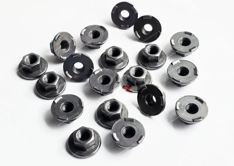
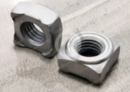
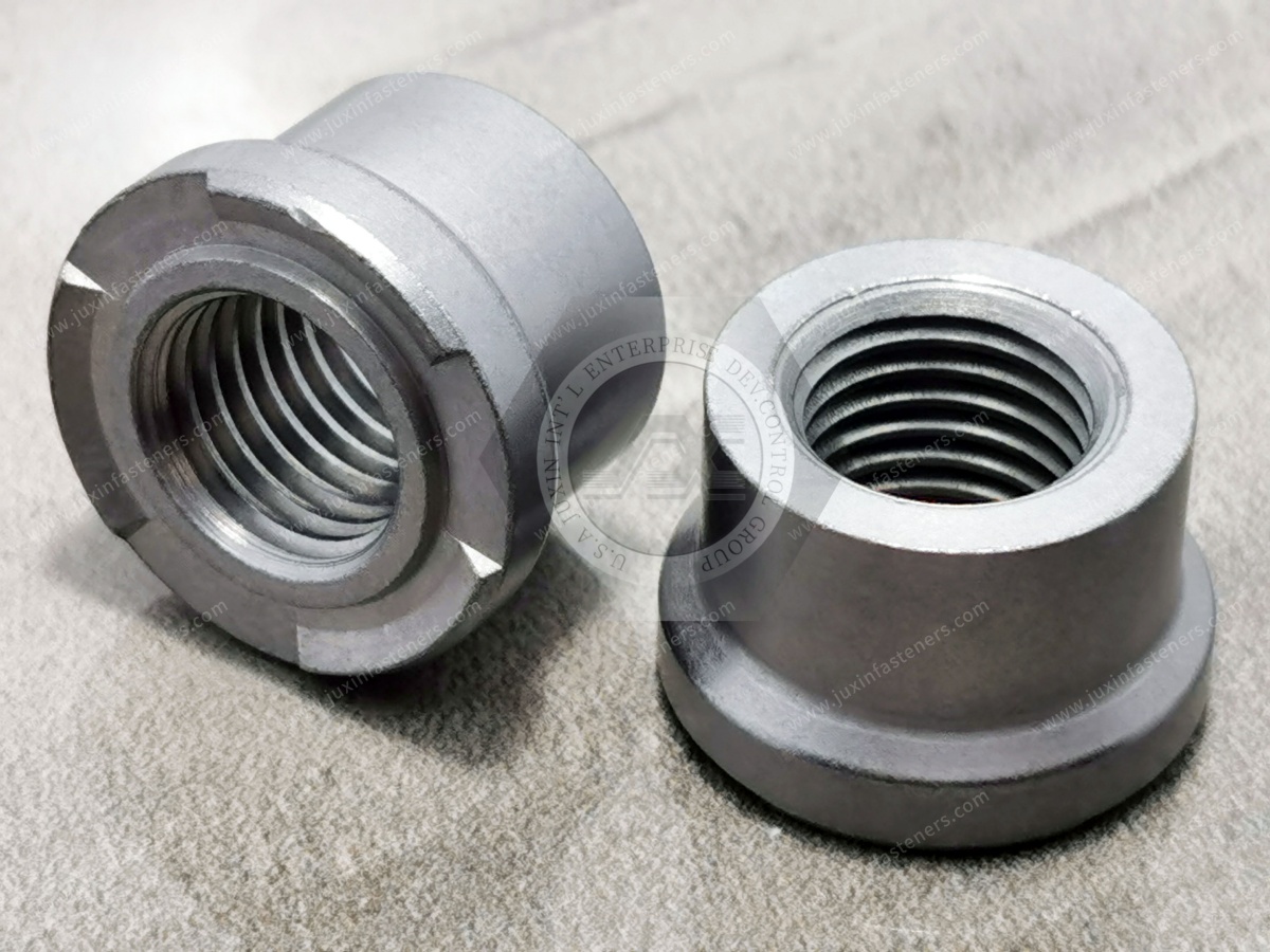
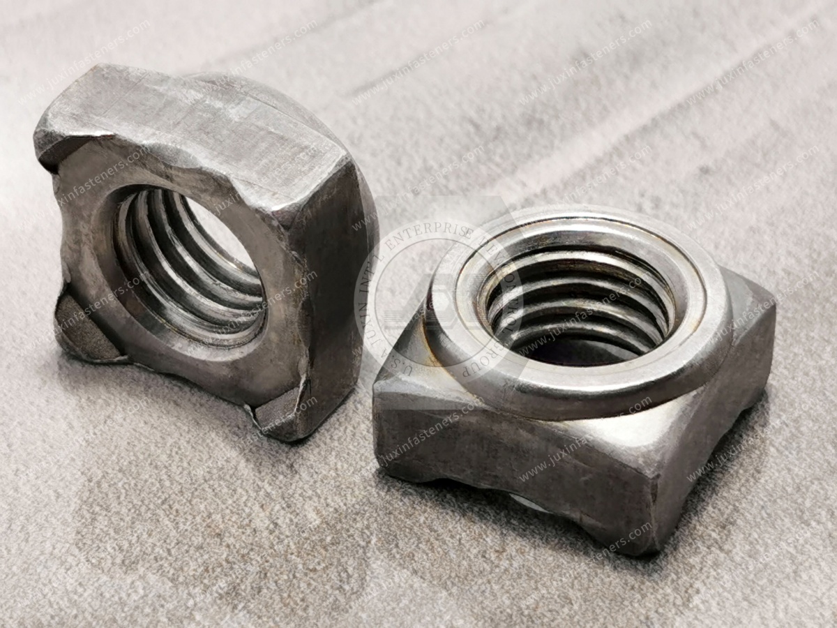
For example, a square weld nut and a hexagon flange weld nut may behave differently in a feeder because their external profiles interact differently with rails and orientation tooling.
This does not mean one geometry is universally better.
The correct geometry depends on the required fastening function and the feeding system.
Nesting occurs when one component becomes partially or completely engaged with another component.
Potential causes can include:
Recessed geometry
Large internal openings
Flange relationships
Sharp corners
Specific length-to-diameter ratios
Projection arrangements
Surface friction
Part orientation
Nesting risk should be evaluated using the actual production component rather than a generic feeder assumption.
Small burrs can have an outsized effect on automated feeding.
Potential consequences include:
Track friction
Orientation failure
Part hang-up
Incorrect sensor triggering
Escapement interference
Damage to neighboring components
For this reason, automated feeding requirements should be included in the manufacturing specification where appropriate.
Weld nuts are frequently used in automated resistance-welding applications.
Common configurations include:
Square weld nuts
Hexagon weld nuts
Hexagon flange weld nuts
Custom projection weld nuts
Relevant engineering characteristics may include:
Projection arrangement
Nut height
Flange geometry
Thread bore
External profile
Part orientation
Welding face
Electrode access
Projection geometry is normally discussed in terms of welding performance.
However, for automated systems, it can also affect:
Part orientation
Contact with feeder tooling
Part stacking
Presentation at the welding station
Robotic pickup
Electrode positioning
This creates an important design connection:
Projection Geometry
       ↓
Welding Performance
       +
Feeding Behavior
       +
Robotic Presentation
Therefore, projection design should not be optimized for welding alone when the component is intended for automated production.
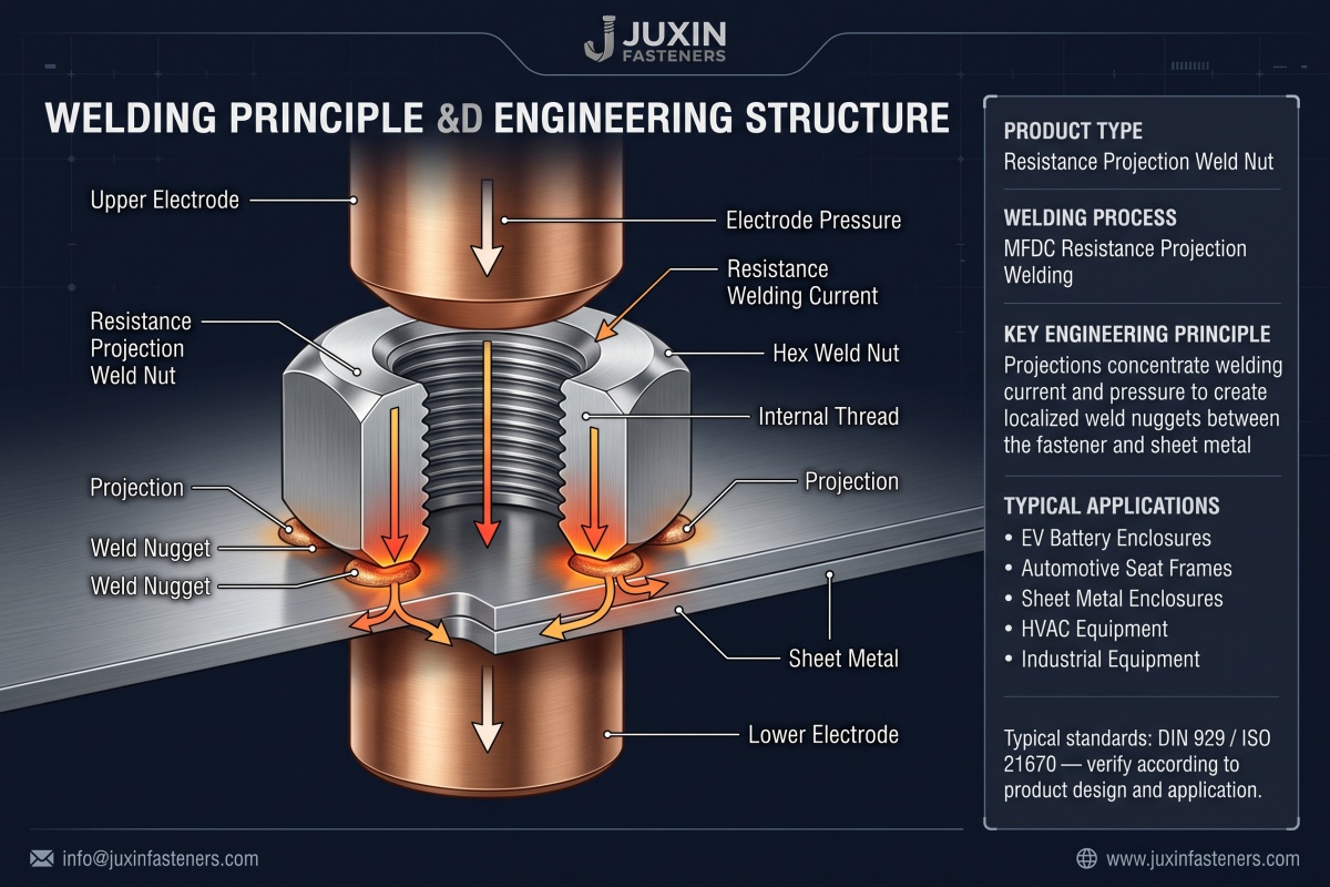
Projection geometry needs to remain within the applicable drawing and process requirements.
However, there is no universal projection-height tolerance that can be applied to every weld nut.
The appropriate dimensional control depends on:
Fastener design
Material
Welding process
Electrode geometry
Sheet material
Sheet thickness
Welding schedule
Customer specification
This is another reason why automated weld fastener qualification should involve both the fastener supplier and the automation/welding engineering team.
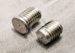
Weld studs introduce different automation considerations.
Depending on the application, automated handling may need to control:
Stud orientation
Head geometry
Shank geometry
Overall length
Thread condition
Surface treatment
Presentation orientation
Welding-gun access
The feeding system must deliver the stud in a repeatable orientation appropriate to the welding equipment.
A stud that is easy to handle manually may require additional orientation features in an automated system.
Thread damage during bulk handling can create downstream assembly problems.
Potential sources include:
Part-to-part impact
Contact with feeder tooling
Improper bulk packaging
Abrasion
Incorrect stacking
Surface-treatment damage
Thread condition should therefore be considered not only at final inspection but also throughout the handling process.
Vibratory bowl feeders are widely used for automated component orientation and feeding.
A typical system includes:
Bulk Hopper / Bowl
        ↓
Vibration
        ↓
Orientation Track
        ↓
Reject / Recirculation
        ↓
Feed Track
        ↓
Escapement
        ↓
Assembly Equipment
The exact architecture varies by equipment manufacturer and application.
Feeder performance depends on:
Component geometry
Part-to-part friction
Surface finish
Part mass
Orientation features
Track geometry
Vibration conditions
Bowl tooling
Escapement design
Therefore, a fastener supplier should not guarantee universal compatibility with every bowl feeder.
Instead, the supplier and automation integrator should evaluate the component against the actual feeding equipment.
Orientation is often one of the most important automation requirements.
For a weld nut, the system may need to distinguish:
Welding face
Thread opening
Flange direction
Projection side
Nut orientation
For a weld stud, orientation may depend on:
Stud head
Threaded shank
Welding end
Application-specific geometry
The orientation method should be selected according to the actual component.
The final stage of the feeder is often more critical than the initial bulk orientation.
The escapement must:
Separate individual components
Present them consistently
Prevent double feeding
Coordinate with the assembly cycle
Avoid damaging the component
Interface with sensors or robotic equipment where applicable
A component can therefore feed successfully through the track but still fail at the escapement.
This is why feeder validation should evaluate the complete feeding path, not just bowl operation.
Some automated systems use pneumatic transport or air-blast feeding.
Potential advantages include:
Flexible routing
Separation between feeder and assembly station
High-speed transfer
Compact line integration
However, performance depends on:
Part geometry
Part mass
Feed-tube dimensions
Surface condition
Airflow characteristics
Orientation
Transfer distance
Accumulation behavior
The fastener should therefore be tested with the actual pneumatic feeding system before production approval.
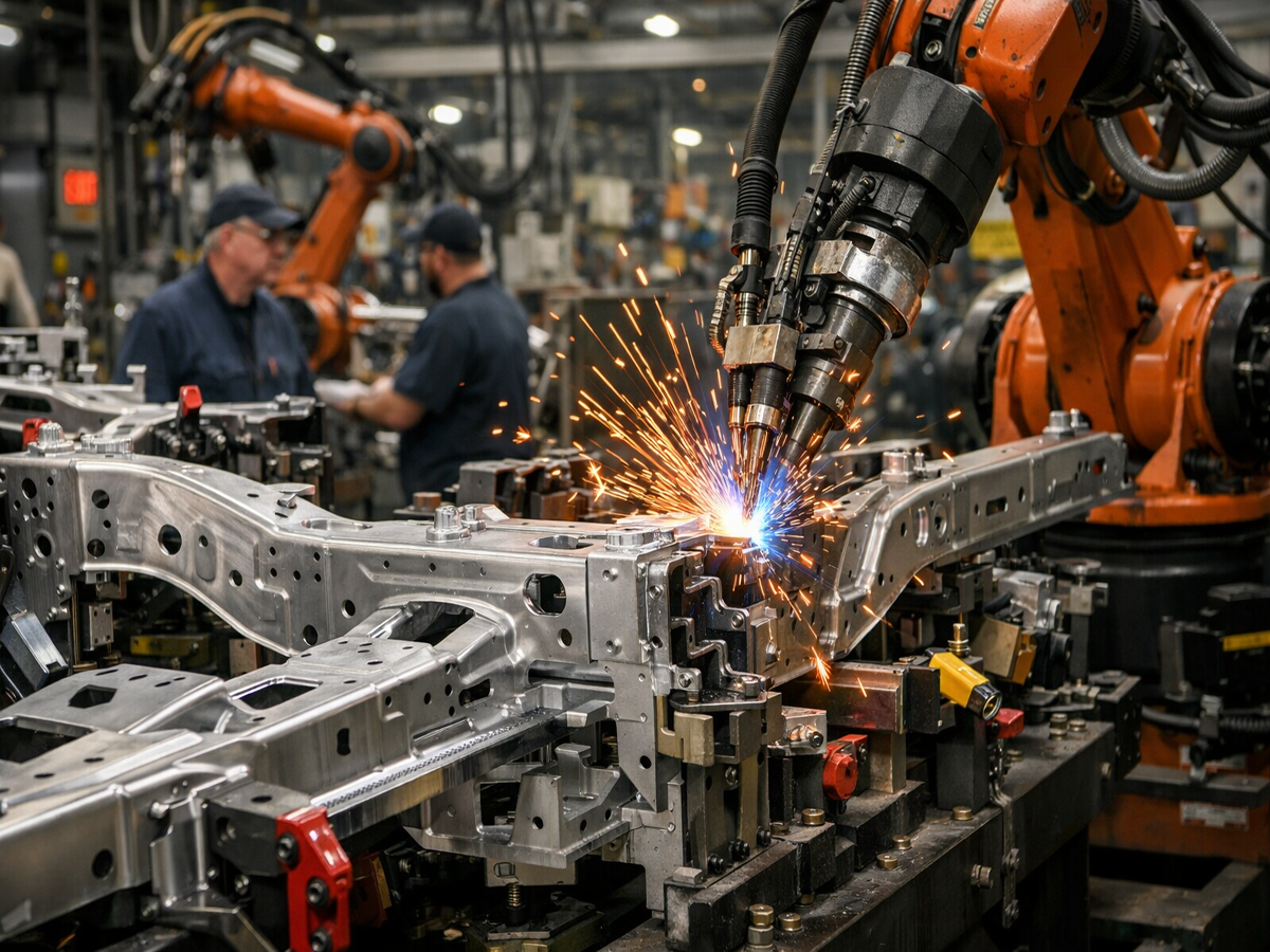
Automated weld fastener systems may combine:
Feeder
Robot
Welding gun
Electrode
Fixture
Sensors
Part-present detection
Weld controller
Production monitoring
The fastener is only one part of the system.
The fastener must reach the welding position without interfering with:
Electrode arms
Welding gun body
Fixtures
Adjacent stamped features
Brackets
Other components
Complex automotive and industrial assemblies can therefore require detailed clearance evaluation.
The robot or applicator needs a repeatable part presentation.
Potential variables include:
Fastener orientation
Pickup location
Transfer distance
Fixture position
Sheet-metal geometry
Welding-gun approach direction
A fastener that feeds reliably but arrives at the wrong orientation can still create an automation failure.
Manufacturing engineers often focus on headline cycle time.
However, fastener automation performance can also be affected by micro-stoppages.
Examples include:
Empty feeder
Double feed
Orientation failure
Jam
Sensor fault
Escapement failure
Part-present failure
Robot pickup failure
Incorrect fastener presentation
A few seconds of interruption repeated throughout a production shift can have a meaningful effect on equipment utilization.
This is why fastener quality and automation performance can influence OEE without the fastener itself being the primary production bottleneck.
Overall Equipment Effectiveness generally considers:
Availability
Performance
Quality
Fastener feeding can influence all three.
For example:
Availability: feeder jams can interrupt production.
Performance: unstable feeding can force slower operating conditions.
Quality: incorrect or damaged fasteners can create assembly defects.
The actual impact should be measured using plant production data rather than assumed universally.
A common mistake is to finalize the fastener design first and only afterward ask the automation integrator to make it feed.
A better approach is:
Fastener Function
       ↓
Fastener Geometry
       ↕
Feeder Concept
       ↕
Robot / Welding Equipment
       ↓
Production Validation
This is particularly important for custom weld fasteners.
During early design review, ask:
How will the part be oriented?
How will nested parts be separated?
Which surface contacts the feeder track?
Which feature determines orientation?
Is the component likely to bridge or rotate?
How will the part be detected?
How will the part be presented to the robot?
Is the welding face clearly defined?
Does the geometry interfere with the electrode?
Does the packaging support bulk feeding?
Does the surface treatment affect handling?
These questions can identify automation problems before tooling investment.
Packaging is often treated as a logistics issue.
For automated fasteners, it is also an engineering issue.
The component moves through:
Manufacturing
→ Inspection
→ Packaging
→ Transportation
→ Receiving
→ Hopper / Bowl
→ Feeder
→ Assembly
If packaging damages or tangles the components, the automation system may experience problems even when the parts were manufactured correctly.
Depending on the component and production system, procurement and manufacturing teams may evaluate:
Bulk quantity
Container dimensions
Part protection
Lot identification
Moisture protection
Interlocking prevention
Handling ergonomics
Returnable packaging
Line-side replenishment
Automated loading
The correct packaging format depends on the actual assembly environment.
There is no universal “best packaging” for all automated fasteners.
Bulk packaging can be appropriate for many automated feeding systems.
However, some applications may benefit from more controlled presentation.
Potential options may include:
Bulk containers
Smaller controlled batches
Compartmentalized packaging
Returnable containers
Pre-oriented components
Application-specific loading systems
The choice should balance:
Feeding performance
Packaging cost
Transportation efficiency
Labor
Part protection
Replenishment frequency
This is a classic TCO decision rather than a piece-price decision.
Surface finish can influence handling behavior.
Factors may include:
Friction
Surface roughness
Coating buildup
Coating consistency
Surface contamination
Burr retention
Part-to-part adhesion
A surface treatment that is appropriate for corrosion protection may still require evaluation in a high-volume feeding system.
For weld fasteners, the surface treatment must also be evaluated against the welding process.
Related engineering considerations can be found in the Fastener Surface Finishes & Coatings: OEM Engineering & Sourcing Guide.
Automated systems magnify certain dimensional variations.
Potentially important characteristics include:
Overall height
Flange diameter
Body width
Thread opening
Projection geometry
Burr condition
Critical profile dimensions
However, not every dimension requires the same tolerance.
The correct approach is to identify functional automation characteristics.
For example:
A dimension that does not affect joint performance during manual assembly may become critical if it determines whether the component passes through an escapement.
This is why engineering drawings for automated fasteners should distinguish between:
Functional joint dimensions
Welding dimensions
Assembly dimensions
Automation-related dimensions
Cosmetic dimensions
A structured failure analysis can accelerate troubleshooting.
| Failure Mode | Possible Contributing Factors | Investigation Direction |
|---|---|---|
| Part nesting | Geometry, opening profile, part interaction | Review part geometry and feeder tooling |
| Track jam | Burr, dimensions, track interface, contamination | Inspect parts and track |
| Wrong orientation | Center of gravity, geometry, orientation tooling | Review orientation mechanism |
| Double feed | Escapement or part interaction | Review separation system |
| Part bridging | Bulk geometry, container or hopper configuration | Review accumulation behavior |
| Pickup failure | Presentation position, robot tooling | Check pickup interface |
| Thread damage | Bulk handling, feeder contact, impact | Review handling path |
| Weld positioning issue | Part presentation, fixture, electrode access | Check complete cell |
| Intermittent feeding | Variation, contamination, tooling wear | Compare good/bad lots and machine conditions |
The table is a troubleshooting framework, not a universal diagnosis.
When feeding problems occur, replacing the fastener immediately may not solve the actual problem.
A better investigation separates:
Geometry
Dimensions
Burrs
Surface condition
Material
Coating
Projection configuration
Track geometry
Bowl tooling
Vibration
Escapement
Sensors
Airflow
Tooling wear
Robot pickup
Welding-gun approach
Fixture
Cycle sequence
Sensor logic
Packaging
Container loading
Transportation
Moisture
Part mixing
This system-level approach is particularly important for intermittent problems.
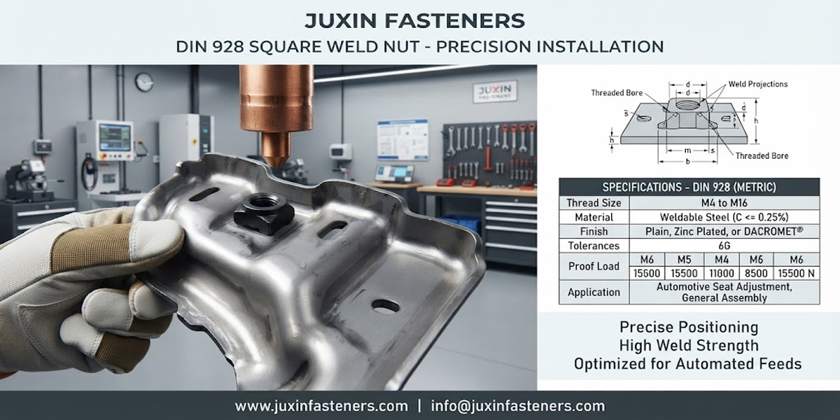
Automation engineers generally need detailed answers about:
Part orientation
Feeder compatibility
Track interface
Escapement
Robotic presentation
Welding-gun clearance
Part detection
Packaging
Production validation
They are usually less interested in a generic statement that a fastener is “high quality.”
They need to understand how the component behaves inside the production system.
Procurement and sourcing teams need a different set of answers:
Can the supplier manufacture the required geometry?
Can the supplier support the required production volume?
Is the component standard or custom?
Is dedicated tooling required?
Can the supplier support DFM?
What quality documentation is available?
Can packaging be developed around the production process?
Can the supplier support engineering changes?
What are the realistic lead times?
What is the total landed cost?
What qualification work is required?
A supplier who answers only the piece-price question is not necessarily solving the OEM's actual sourcing problem.
If a fastener will be automatically fed, the RFQ should say so.
Useful information includes:
Part number
2D drawing
3D CAD model
Material
Thread
Surface treatment
Annual volume
Feeder type
Orientation requirement
Feed direction
Escapement requirements
Robot interface
Welding equipment
Assembly equipment
Expected operating conditions
Container type
Container quantity
Line-side replenishment
Returnable packaging requirements
Lot identification
Moisture protection where required
Critical dimensions
Inspection requirements
Functional testing
Welding validation
Traceability requirements
Customer-specific documentation
This information allows the supplier to evaluate the fastener as part of the production system.
Custom fasteners can be particularly useful when standard geometry creates automation limitations.
Potential reasons for customization include:
Better orientation
Reduced nesting
Improved welding access
Improved robotic pickup
Better sheet-metal interface
Specific thread requirements
Packaging requirements
Special projection geometry
However, customization should be driven by a measurable engineering requirement.
Custom does not automatically mean better.
A standard fastener may be preferable when it already meets the mechanical, welding, automation, and procurement requirements.
For custom requirements, the Custom Weld Fasteners: Engineering & OEM Manufacturing solution provides a logical next step for design and sourcing discussions.
Automotive Body-in-White manufacturing is a major application for automated weld fastener handling.
Potential components include:
Weld nuts
Weld studs
Projection weld fasteners
Automated BIW environments may involve:
Robotic resistance welding
High-volume feeding
Automated part presentation
Complex sheet-metal geometry
Multiple welding stations
Tight production schedules
The fastener must therefore be evaluated for both welding and automated handling.
For automotive programs, customer drawings, process specifications, validation requirements, and production equipment determine the appropriate qualification criteria.
The Automotive Body-in-White Weld Fasteners solution can be used as a related engineering reference.
Automated fastening is also relevant to:
Electrical enclosures
Switchgear
Industrial machinery
HVAC equipment
Appliances
Commercial equipment
These applications may use:
Weld nuts
Weld studs
Self-clinching fasteners
Threaded inserts
CNC-machined fastening components
The automation strategy depends on production volume and assembly complexity.
Not every industrial application benefits economically from fully automated feeding.
This is another important procurement decision:
Automation should be justified by production economics and process requirements, not simply because automation is available.
Automation investment should consider more than feeder purchase price.
A broader calculation may include:
Feeder / Automation Equipment
+
Tooling
+
Integration
+
Programming
+
Maintenance
+
Packaging
+
Line-Side Handling
+
Fastener Cost
+
Quality Cost
+
Downtime / Micro-Stoppage Cost
=
Total Automation Cost
The correct model depends on the production line.
For high-volume production, improved feeding stability may justify additional engineering work.
For low-volume production, manual or semi-automated handling may remain more economical.
When sourcing automated fasteners, supplier qualification should cover more than dimensional inspection.
Review:
Geometry
Material
Thread
Surface treatment
Projection configuration
Burr condition
Manufacturing process
Tooling
Inspection
Nonconformance management
Change control
Feeding requirements
Packaging
Orientation
Production validation
Capacity
Lead time
Forecast planning
Packaging replenishment
Logistics
A supplier should be evaluated according to the actual application rather than using generic “automation-ready” claims.
A practical validation program may include:
Dimensional inspection
Thread inspection
Material verification where specified
Surface-treatment verification where specified
Orientation
Track passage
Escapement
Pickup
Nesting behavior
Jam behavior
Fastener presentation
Electrode access
Welding process
Weld integrity
Joint performance
Sustained production run
Packaging replenishment
Part identification
Lot traceability
Process stability
The exact test method and acceptance criteria should be defined by the customer, equipment integrator, engineering specification, or approved validation plan.
A common reaction to automation problems is:
“Make every dimension tighter.”
This can increase manufacturing cost without addressing the actual failure mechanism.
For example, if a component jams because of an unfavorable feeder-track interaction, reducing an unrelated dimensional tolerance may provide no benefit.
A better approach is:
Observe Failure
      ↓
Identify Functional Characteristic
      ↓
Determine Physical Mechanism
      ↓
Modify Geometry / Process / Feeder
      ↓
Validate
This approach creates a more efficient engineering solution.
The goal is not maximum dimensional precision.
The goal is sufficient control of the characteristics that actually determine automation performance.
An effective OEM sourcing process can begin with the production problem rather than the product name.
For example:
Production problem:
Weld nuts intermittently jam during automated feeding.
Then investigate:
Fastener geometry
Nesting behavior
Feeder tooling
Packaging
Surface condition
Escapement
Orientation
The commercial path becomes:
Automation Problem
        ↓
Application Information
        ↓
Fastener Drawing / CAD
        ↓
Feeder & Welding Requirements
        ↓
DFM Review
        ↓
Prototype / Sample Validation
        ↓
Production Qualification
        ↓
Commercial RFQ
        ↓
Long-Term OEM Supply
This is more effective than simply asking a supplier:
“Can you supply weld nuts for our feeder?”
The following JUXIN FASTENERS solution pages can be connected to an automated feeding project depending on the engineering requirement.
The Fastener Packaging & Feeder Compatibility guide addresses packaging, feeder interaction, orientation, bulk handling, and line-side supply considerations.
The Custom Weld Fasteners: Engineering & OEM Manufacturing guide is relevant when fastener geometry needs to be developed around a specific welding or automation requirement.
The Fastener Geometric Tolerancing & Thread Classes guide explains how functional dimensions, thread requirements, positional control, and tolerance strategy affect engineered fasteners.
The Automotive Body-in-White Weld Fasteners solution addresses automated automotive welding applications and OEM sourcing considerations.
The Fastener Procurement & RFQ Best Practices guide helps procurement teams prepare the technical and commercial information needed for comparable supplier quotations.
The Global Fastener Procurement & RFQ Strategy guide connects automated fastener sourcing with supplier qualification, TCO, production planning, and supply-chain risk.
The Fastener Failure Modes & Root Cause Analysis guide is relevant when feeding or assembly problems create recurring production defects.
The Fastener Surface Finishes & Coatings: OEM Engineering & Sourcing Guide should be reviewed when surface treatment affects corrosion protection, welding, thread condition, or automated handling.
The Fastener Supply Chain Risk Management guide addresses supplier diversification, inventory planning, lead-time risk, and supply continuity for critical production fasteners.
No.
Feeder compatibility depends on the relationship between the fastener geometry and the actual feeding equipment.
Factors such as part profile, center of gravity, nesting behavior, surface condition, dimensions, orientation features, track geometry, and escapement design can affect performance.
No.
Dimensional consistency is important, but feeding performance also depends on part geometry, feeder tooling, orientation, surface condition, packaging, and equipment setup.
A dimensionally conforming part can still be poorly suited to a particular feeder configuration.
Compatibility should be evaluated against the actual fastener and feeder configuration.
JUXIN FASTENERS can review available drawings, CAD data, application information, packaging requirements, and automation requirements as part of an engineering sourcing discussion,
but universal compatibility with every feeder should not be assumed.
Yes.
If automated feeding is part of the production process, the RFQ should identify the relevant feeder, orientation, presentation, welding, packaging, and assembly requirements.
This allows the supplier to evaluate the fastener as an automation component rather than only as a machined or formed part.
Not universally.
Square and hexagon geometries have different mechanical, welding, orientation, and feeding characteristics.
The correct selection depends on the application, welding process, feeder configuration, sheet-metal interface, and assembly requirements.
No.
A custom geometry may solve a specific orientation, nesting, or welding-access problem, but it can also increase tooling cost, qualification requirements, and supply-chain complexity.
Customization should therefore be justified by a defined engineering requirement.
Yes.
Packaging can influence part nesting, contamination, damage, moisture exposure, bulk loading, and replenishment.
For automated applications, packaging should be considered part of the overall material-handling system.
Useful information includes:
2D drawing
3D CAD model
Part material
Thread specification
Surface treatment
Annual volume
Feeder type
Orientation requirements
Welding equipment
Packaging requirements
Assembly environment
Quality requirements
The more complete the information, the more effectively the supplier can evaluate the requirement.
Fastener geometry has been reviewed for automated handling
Orientation requirement is defined
Nesting/interlocking risk has been evaluated
Critical automation dimensions are identified
Thread requirements are defined
Welding requirements are defined
Electrode access has been considered
Feeder type is known
Track interface has been evaluated
Escapement has been considered
Part presentation is defined
Robot pickup is validated where applicable
Sensors and detection are considered
Production validation is planned
Bulk quantity is defined
Container format is defined
Part protection is considered
Lot identification is maintained
Line-side replenishment is considered
Packaging does not create excessive nesting or damage
Annual volume is defined
Forecast information is available
Tooling requirements are understood
Quality documentation is defined
Lead time is evaluated
Total cost of ownership is considered
Engineering changes are controlled
JUXIN FASTENERS supports OEM and industrial fastening requirements across a range of engineered component categories, including:
Weld nuts
Weld studs
Self-clinching fasteners
Blind rivet nuts
Threaded inserts
CNC-machined fasteners
Custom screws and bolts
Stainless steel fasteners
High-strength fasteners
Custom engineered fastening components
For automated applications, the fastener should be evaluated according to the actual manufacturing environment.
Relevant considerations may include:
Part geometry
Material
Thread
Projection configuration
Surface treatment
Welding process
Feeder requirements
Packaging
Annual volume
Inspection
Customer specifications
JUXIN FASTENERS can support technical discussions around custom fastener development, DFM, application-specific fastening requirements,
welding considerations, automated assembly requirements, and OEM procurement.
The goal is not to label a fastener “automation-ready” without qualification.
The goal is to determine whether the fastener, feeder, welding system, packaging, and production process can work together effectively.
If your manufacturing line uses automated fastener feeding, robotic welding, automated assembly, or high-volume component handling, provide the available production information for engineering review.
Recommended RFQ information includes:
Fastener drawing
3D CAD model
Material requirement
Thread specification
Surface-treatment requirement
Welding process
Feeder type
Orientation requirement
Robotic application
Packaging requirement
Annual volume
Forecast
Prototype quantity
Production schedule
Inspection requirements
Delivery requirements
For custom weld fasteners, early engineering involvement can help identify whether the existing geometry should be retained, modified, or redesigned around the automated production system.
Email: info@juxinfasteners.com
JUXIN FASTENERS — Precision Fastening Solutions Since 2003.
Product Packaging
Packaging Standard
At Juxin Fasteners, we apply standardized export packaging to ensure product protection, traceability, and compliance with international logistics requirements.
1. Standard Export Packaging
Unless otherwise specified, all products will be packed according to our factory standard export packaging, which includes:
Moisture-resistant inner protection
Poly bag or small box packing as required
Reinforced export cartons
Clear labeling with part number, specification, batch number, and quantity
Palletizing for sea or air shipment when necessary
Our standard packaging is designed to ensure safe transportation, efficient warehousing, and long-distance international shipping.
2. Customized Packaging Options
We also provide customized packaging solutions according to customer requirements, including but not limited to:
Private labeling
Customized barcodes
Specific carton dimensions
Retail packaging
Special pallet configuration
Customer-specific marking and identification
So that you know, customized packaging may involve additional costs and extended lead time depending on the complexity of the requirements.
3. Compliance & Quality Assurance
All packaging processes are controlled under our ISO 9001 quality management system to ensure consistency, traceability, and product integrity throughout the supply chain.
Product Pictures
Contact Us
Tel.:
+86 020 8621 0320
+86 020 3121 6067
E-mail:
Technical Support:
Navigation
SEND INQUIREY