Call Us
+86 136 6007 9809
Call Us
+86 136 6007 9809

How do structural and assembly engineers control the relationship between tightening torque and clamping preload in a threaded joint?
The fastener torque-tension relationship describes how an applied tightening torque is converted into axial tension in a fastener and, consequently, clamping force across the joint.
Product Specification
How do structural and assembly engineers control the relationship between tightening torque and clamping preload in a threaded joint?
The fastener torque-tension relationship describes how an applied tightening torque is converted into axial tension in a fastener and, consequently, clamping force across the joint.
A simplified engineering relationship is often expressed as:
T = K × d × F
where:
T = tightening torque;
K = an empirical torque coefficient representing the combined influence of friction and joint geometry;
d = nominal fastener diameter;
F = resulting fastener preload or tensile force.
This equation is useful as a simplified engineering model, but it should not be treated as a universal production specification.
The reason is important:
Most of the tightening torque applied to a threaded fastener is consumed by friction at the thread and bearing interfaces. Only a smaller portion contributes directly to elastic stretching of the fastener.
Therefore, two fasteners with the same nominal diameter, material, and torque setting can generate materially different preload if their:
surface finish;
coating;
lubrication;
thread condition;
bearing interface;
washer configuration;
manufacturing process;
assembly history
are different.
This is why controlling tightening torque alone does not automatically mean controlling clamping force.
For OEM production, the engineering objective is to establish a validated relationship between the specified tightening method, actual friction condition,
fastener geometry, joint stiffness, and required preload window.
A practical torque-tension system can be viewed as:
Applied Torque → Thread & Bearing Friction → Fastener Elastic Elongation → Preload → Joint Clamping Force → Joint Performance
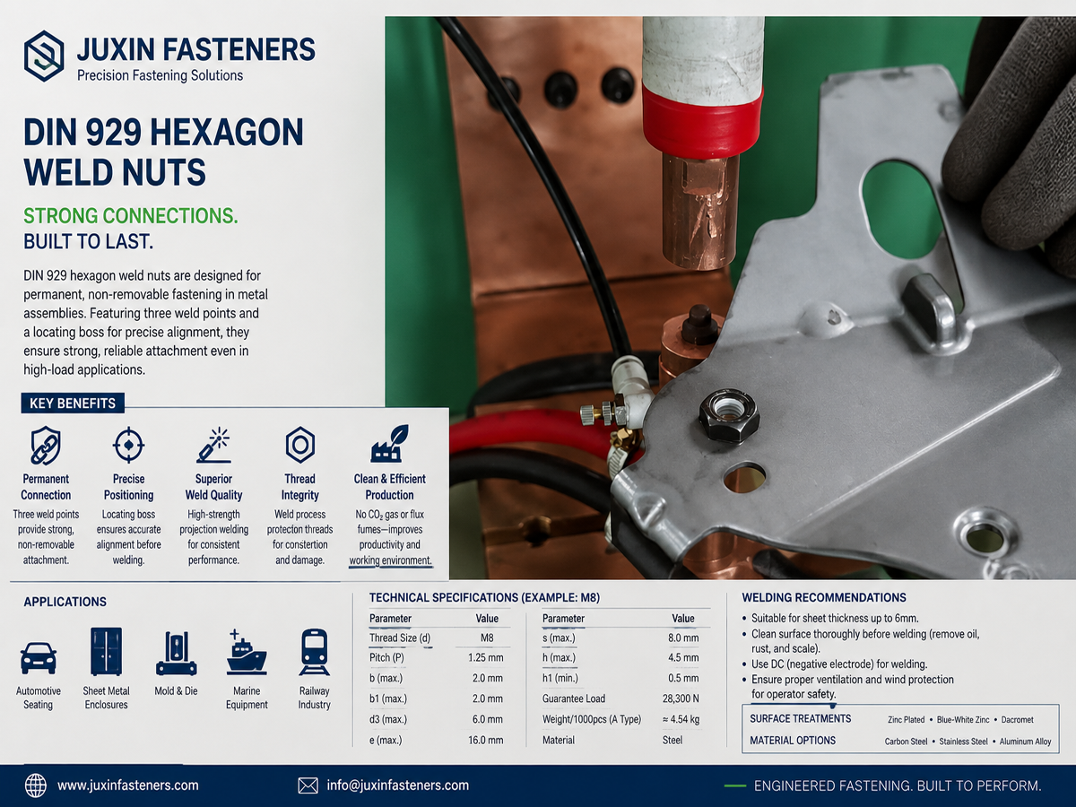
For applications involving weld nuts, weld studs, self-clinching fasteners, rivet nuts, custom screws, or conventional bolts, the fastener interface must also remain mechanically stable during tightening.
JUXIN FASTENERS supports OEM applications involving precision weld fasteners, self-clinching fasteners, blind rivet nuts, threaded inserts, custom screws and bolts,
CNC-machined fasteners, stainless steel fasteners, and high-strength fastener applications.
The correct engineering question is therefore not simply:
“What torque should we use?”
It is:
“What preload does the joint require, what tightening method will produce it consistently, and how will that relationship be validated in production?”
A tightening tool applies rotational energy.
The joint requires controlled axial force.
These are not the same physical quantity.
When a bolt or screw is tightened, the applied torque is consumed by several mechanisms, including:
thread friction;
bearing-surface friction;
thread geometry;
elastic deformation of the fastener;
deformation of the joint components;
surface interaction;
installation conditions.
The useful output is the tensile force generated in the fastener and the corresponding compression applied to the joint.
This creates the fundamental engineering problem:
Torque is easy to measure. Preload is what the joint actually needs.
The simplified relationship:
T = K × d × F
is widely used because it provides a convenient first-order connection between torque, diameter, and preload.
However, the K-factor is not a universal material constant.
It is an empirical coefficient influenced by the complete friction condition of the assembly.
Changes in:
plating;
conversion coating;
lubricant;
thread surface;
nut or bolt bearing surface;
washer;
contamination;
installation speed;
repeated assembly;
temperature;
surface roughness
can change the torque required to achieve a particular preload.
Therefore, inserting a generic K value into a production calculation without validating the actual fastener condition can create misleading results.
Many engineering articles provide a nominal K-factor as a convenient example.
That can be useful for preliminary calculations.
It should not automatically become the production torque specification.
If the actual friction condition produces a different K-factor, the same torque setting can generate a different preload.
For example, a lower-friction coating or lubrication condition can cause more of the applied torque to be converted into fastener tension.
At the same torque setting, this can increase preload and potentially move the fastener closer to its elastic or yield limit.
Conversely, a higher-friction condition can consume more torque in friction and produce less preload than expected.
This is why friction control is one of the central engineering variables in torque-tension management.
A useful conceptual model separates the applied torque into:
thread friction;
bearing friction;
useful torque associated with generating fastener tension.
The exact percentage distribution is not universal.
It changes with:
thread geometry;
friction coefficient;
bearing diameter;
coating;
lubrication;
fastener dimensions;
installation condition.
Therefore, fixed statements such as “half of the torque always goes into thread friction” or “only ten percent becomes preload” should not be used as universal engineering rules.
The more useful Information Gain is understanding why the distribution changes.
Thread friction occurs between the mating thread flanks.
It is influenced by:
thread surface condition;
coating;
lubrication;
thread angle;
dimensional condition;
surface roughness;
contamination.
Thread friction directly influences the torque required to generate a given axial force.
Bearing friction occurs where the rotating fastener component contacts the bearing surface.
This may be:
bolt head to joint surface;
nut face to joint surface;
nut to washer;
bolt head to washer.
Changing the bearing interface can therefore change the torque-tension relationship even when the threaded portion remains unchanged.
As the fastener is tightened, it stretches elastically.
This elongation generates tensile force.
At the same time, the clamped components are compressed.
The joint therefore behaves as a mechanical spring system.
The relationship between fastener stiffness and joint stiffness influences how the joint responds to external loading.
A bolt does not operate independently.
A bolted joint typically contains:
fastener;
nut or threaded insert;
washers where applicable;
clamped components;
bearing surfaces;
interfaces between the components.
The target preload should therefore be determined from the joint design and load requirements.
Important factors can include:
external tensile load;
shear loading;
joint separation risk;
fatigue loading;
joint stiffness;
embedding or settling;
thermal expansion;
vibration;
friction between clamped parts;
fastener strength;
thread capacity.
This is why a generic “tighten to X Nm” instruction can be inadequate for a critical structural joint.
The tightening process must keep the fastener within the intended mechanical operating range.
For applicable carbon and alloy steel bolts, screws, and studs, ISO 898-1 defines mechanical property requirements for specified property classes.
However, ISO 898-1 should not be interpreted as a universal specification for every type of industrial fastener.
For example, weld nuts, self-clinching nuts, rivet nuts, and other internally threaded components require application-specific evaluation.
The engineering team should consider:
fastener material;
applicable mechanical standard;
nominal diameter;
stress area;
thread specification;
property class where applicable;
nut or insert strength;
parent material;
joint stiffness;
required preload.
A stronger fastener does not automatically mean the joint should be tightened to the maximum possible load.
The joint may be limited by:
thread stripping;
parent material deformation;
bearing failure;
insert pull-out;
weld-nut failure;
sheet-metal deformation;
local crushing;
component distortion.
Therefore:
Fastener capacity ≠ joint capacity ≠ recommended assembly preload.
This distinction is particularly important when using fasteners installed into relatively thin sheet metal or polymer components.
Laboratory calculations can produce a clean torque-preload relationship.
Mass production introduces variation.
Potential sources include:
coating variation;
lubricant variation;
thread dimensional variation;
surface roughness;
tool variation;
operator variation;
installation speed;
temperature;
fastener reuse;
contamination;
washer variation;
joint surface variation.
This creates preload scatter.
A production line may use the same nominal torque setting while actual clamp loads vary across individual assemblies.
That is why critical OEM fastening systems require validation rather than relying solely on a theoretical torque equation.
Surface treatment is directly connected to torque-tension behavior.
A coating selected only for corrosion resistance can create unexpected assembly behavior if its friction characteristics are not considered.
Potential surface-treatment systems include:
zinc plating;
trivalent chromium zinc plating;
zinc-nickel;
zinc-aluminum;
zinc-flake systems;
stainless passivation;
application-specific anti-corrosion treatments.
Each coating system may interact differently with:
thread friction;
bearing friction;
lubrication;
assembly tools;
installation speed;
repeated tightening.
Therefore, corrosion specification and friction specification should be evaluated together when the assembly torque is critical.
This is particularly relevant to automotive, EV, industrial equipment, electrical equipment, and other high-volume OEM assemblies.
Lubrication reduces friction under many conditions.
That sounds beneficial.
But if a production torque value was developed using an unlubricated fastener and the production fastener later receives a lubricant or low-friction topcoat, the same torque may generate a different preload.
This can create two opposite risks:
If friction is higher than expected, the specified torque may fail to generate sufficient clamp load.
Possible consequences include:
joint separation;
micro-movement;
fretting;
fatigue concerns;
vibration-related loosening.
If friction is lower than expected, the same torque may produce excessive fastener tension.
Possible consequences include:
yielding;
permanent elongation;
thread damage;
fastener fracture;
excessive joint compression.
Therefore, any change to the coating or lubrication system should be treated as a potentially important engineering change for torque-controlled assemblies.
Torque-angle tightening adds controlled angular rotation after a defined initial tightening stage.
The concept can reduce dependence on friction during the later angular portion of tightening because the relationship between rotation and fastener elongation becomes an important control variable.
However, torque-angle tightening is not automatically the best method for every joint.
Its suitability depends on:
fastener design;
joint stiffness;
required preload;
fastener strength;
intended tightening strategy;
assembly equipment;
production capability;
customer specifications.
Torque-angle methods can be particularly useful where the engineering strategy intentionally controls fastener elongation or a defined tightening sequence.
The method still requires validation.
For critical applications, engineers may directly measure or indirectly verify preload.
Possible techniques include:
load cells;
instrumented fasteners;
strain-gauged bolts;
ultrasonic bolt elongation measurement;
torque-tension testing;
controlled assembly rigs;
statistical production monitoring.
The appropriate method depends on:
joint accessibility;
fastener geometry;
production volume;
required accuracy;
cost;
validation stage.
Torque-tension testing can establish the actual relationship between:
Torque → Friction → Preload
for a defined fastener and coating condition.
This can be more useful than relying on a theoretical K-factor because it evaluates the actual production fastener configuration.
The test should represent the intended:
fastener;
nut or threaded insert;
coating;
lubrication;
washer;
assembly condition.
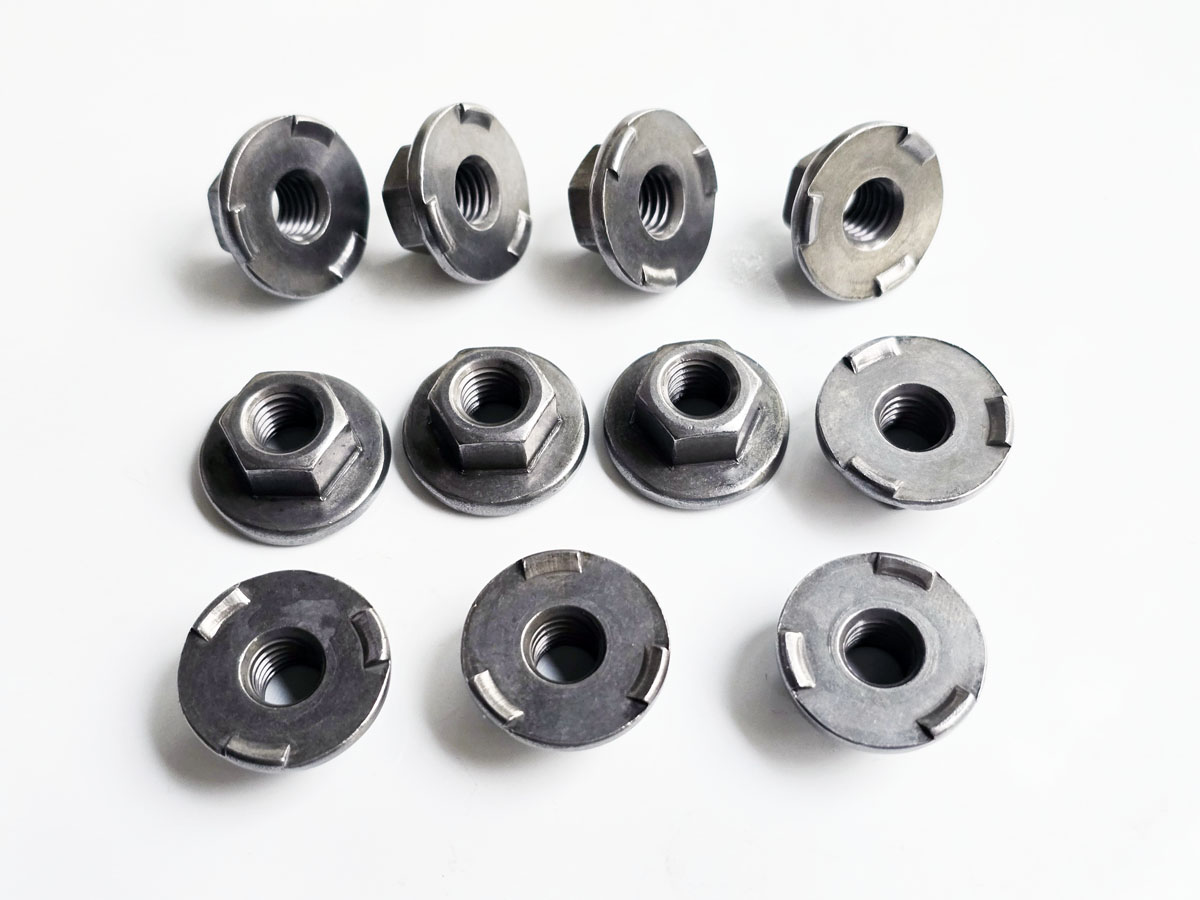
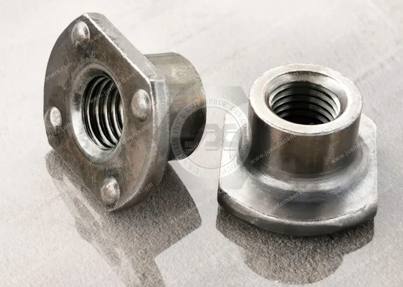
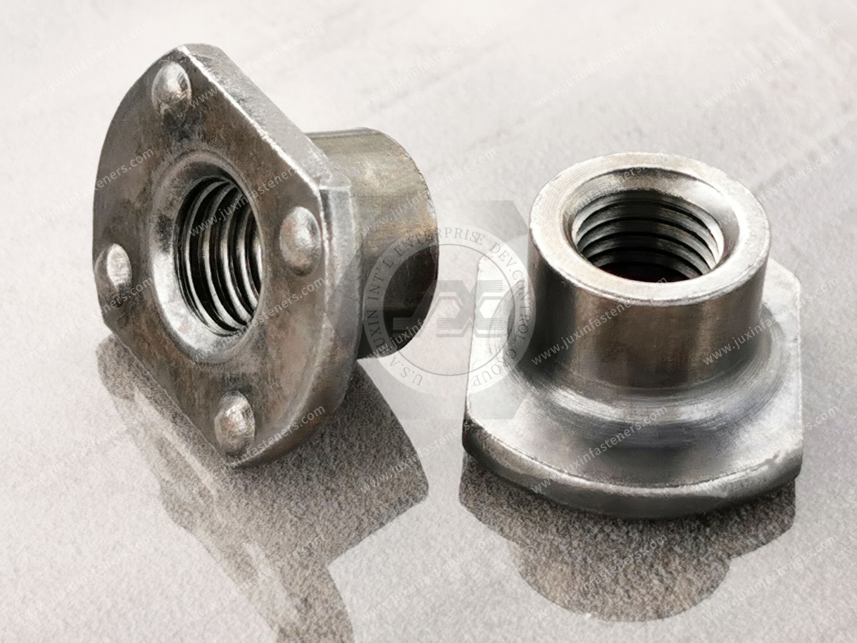
Weld nuts are commonly used when a permanent internal thread is required in sheet-metal assemblies.
Typical configurations include:
hex weld nuts;
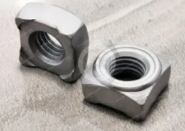
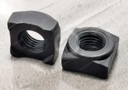
square weld nuts;
flange weld nuts;
specialty weld nuts;
custom projection-welded nuts.
Their primary mechanical advantage is that the welding process creates a fixed threaded fastening point that resists rotation during bolt installation.
This is especially useful where the rear side of the sheet is inaccessible.
If a conventional nut rotates during tightening, the assembly process becomes impractical or requires access to both sides of the joint.
A properly designed weld nut provides a stable internal thread.
However, the existence of a welded connection does not automatically guarantee a particular torque capacity.
Actual performance depends on:
weld design;
projection geometry;
parent sheet;
weld process;
weld quality;
nut geometry;
thread specification;
installation conditions;
applied torque;
failure mode.
Possible failure modes may include:
thread stripping;
nut deformation;
weld failure;
sheet deformation;
local pull-out;
fastener fracture.
Therefore, weld-nut torque performance should be validated against the actual joint design.
Self-clinching nuts provide another method for creating permanent internal threads in sheet metal.
Their performance depends on:
parent material;
sheet thickness;
hole geometry;
fastener design;
installation process;
installation force;
anti-rotation engagement;
thread specification.
The engineering team should distinguish between:
installation force of the self-clinching fastener
and
assembly torque applied later to the mating screw or bolt.
These are separate engineering variables.
A self-clinching nut that is correctly installed can provide a stable threaded connection, but its torque capacity must still be appropriate for the specific sheet material and design.
Blind rivet nuts are useful where installation access is available from only one side.
They are commonly used in:
vehicle structures;
equipment enclosures;
electrical cabinets;
HVAC systems;
industrial machinery;
fabricated sheet-metal assemblies.
Unlike a welded nut, a blind rivet nut is mechanically expanded or deformed during installation.
Its performance depends on:
parent material;
hole condition;
grip range;
rivet-nut geometry;
installation process;
thread size;
material;
required assembly load.
For this reason, procurement teams should not treat a rivet nut as simply a “blind version of a weld nut.”
The installation mechanism and failure modes are different.
The mating thread must have sufficient effective engagement to transmit the intended load.
But thread engagement should not be expressed as a universal number independent of:
material strength;
thread diameter;
thread form;
internal-thread material;
external-thread material;
joint loading;
manufacturing tolerance.
This is particularly important for:
aluminum;
thin steel sheet;
brass;
engineering plastics;
threaded inserts.
A high-strength screw installed into a weaker threaded component may not reach its own tensile limit before the internal thread fails.
Therefore:
The weakest component in the load path can control the usable joint capacity.
High-strength fasteners require careful tightening control because increased mechanical capacity can also increase the consequences of incorrect preload.
Relevant risks can include:
excessive tensile stress;
hydrogen embrittlement risk for susceptible materials and processing conditions;
thread damage;
fatigue;
preload loss;
coating-related friction changes.
For electroplated high-strength fasteners, hydrogen embrittlement controls should be considered as part of the coating process and specification.
ISO 4042 provides requirements and recommendations for electroplated fastener coating systems, including measures intended to minimize hydrogen embrittlement risk.
The coating decision should therefore be made together with:
strength + friction + corrosion + manufacturing process + assembly requirements.
A common misconception is:
“Correct torque means the joint can never loosen.”
That is not correct.
Joint loosening can result from:
insufficient preload;
transverse vibration;
joint slip;
embedding;
settling;
external load;
insufficient friction between clamped components;
fastener rotation under specific dynamic conditions.
Correct tightening is one part of joint reliability.
The complete design may also require:
appropriate joint stiffness;
suitable thread design;
locking features where justified;
correct surface condition;
controlled preload;
environmental validation.
For vibration-sensitive applications, engineers should therefore evaluate both preload retention and rotational loosening resistance.
When an external tensile load is applied to a bolted joint, the load is shared between:
the fastener;
the clamped components.
The exact load distribution depends on the stiffness of the joint components.
This is why a joint with a high initial preload can behave differently from a lightly preloaded joint under the same external load.
The design engineer should consider:
fastener stiffness;
clamped-member stiffness;
joint geometry;
preload;
external load;
separation risk;
fatigue loading.
This becomes particularly important in:
automotive chassis;
structural brackets;
heavy equipment;
rotating machinery;
industrial machinery;
power equipment.
Temperature changes can affect joint preload when fastener and clamped materials have different coefficients of thermal expansion.
This is particularly relevant to multi-material assemblies involving:
steel;
aluminum;
stainless steel;
engineered polymers;
composite structures.
A joint may therefore experience preload changes during thermal cycling even if the assembly torque remains unchanged.
For applications involving significant temperature changes, the engineering team should consider:
material combinations;
thermal expansion;
fastener length;
joint stiffness;
temperature range;
preload requirements.
Surface coating adds material to the fastener surface.
This can influence:
thread dimensions;
fit;
friction;
bearing behavior;
installation torque;
assembly consistency.
The effect depends on:
coating system;
coating thickness;
thread geometry;
tolerance;
post-treatment;
lubrication.
Therefore, coating selection should not be separated from dimensional control.
This is particularly important for precision OEM assemblies where automated tools are used.
A theoretical torque specification becomes useful only when it works on the production line.
A practical validation process can include:
Establish a preliminary preload target from the joint design.
Select:
fastener material;
geometry;
thread;
coating;
nut or insert type.
Measure the actual relationship between torque and preload under the intended surface condition.
Verify:
torque capability;
angle control where applicable;
tool repeatability;
socket condition;
installation speed.
Test the complete joint rather than the fastener alone.
Monitor the assembly process for:
torque scatter;
angle scatter;
tool drift;
fastener variation;
coating variation.
Revalidate when changing:
coating;
lubricant;
supplier;
fastener material;
thread specification;
washer;
assembly tool;
manufacturing process.
This is the difference between a theoretical torque number and a controlled OEM fastening process.
When purchasing fasteners for a torque-critical application, procurement should ask more than:
“What is the unit price?”
Important questions include:
What fastener type is being supplied?
What material is specified?
What thread standard applies?
What dimensional tolerances are controlled?
What coating system is used?
Is there a conversion coating?
Is lubrication included?
Are friction requirements specified?
Is a torque specification already defined?
Is torque-tension validation required?
Is torque-angle tightening required?
Is the fastener intended for one-time or repeated assembly?
What inspection records are available?
How is batch traceability maintained?
How are coating changes controlled?
How are nonconforming batches handled?
What is the annual capacity?
What is the standard production lead time?
What is the change-notification process?
Can the supplier support prototype-to-production transition?
These questions help procurement teams evaluate the total supply-chain risk, not just the quoted price.
A good RFQ should include as much of the following as applicable:
2D engineering drawing;
3D model;
fastener type;
thread specification;
material;
mechanical requirements;
surface treatment;
lubrication requirement;
parent material;
joint configuration;
target preload;
tightening torque;
tightening angle if applicable;
assembly tool type;
torque-tension validation requirement;
corrosion requirement;
annual volume;
forecast;
packaging;
traceability;
inspection documentation;
applicable international standards;
customer-specific requirements.
If the torque specification has already been developed, the supplier should be informed whether it is based on:
calculation;
historical production data;
torque-tension testing;
customer specification;
joint-level validation.
This information helps prevent accidental changes to the friction condition that could invalidate an existing torque specification.
| Requirement | Engineering Question | Potential JUXIN FASTENERS Solution |
|---|---|---|
| Permanent internal thread in sheet metal | Is rear-side access limited? | Weld nuts |
| Permanent anti-rotation fastening point | Is welding available? | Weld nuts / weld studs |
| One-sided installation | Is the rear side inaccessible? | Blind rivet nuts |
| Thin sheet metal | Can the parent material support the required joint? | Self-clinching fasteners |
| Plastic housing | Is a reusable internal thread required? | Threaded inserts for plastic |
| High-strength threaded connection | What material and property requirements apply? | High-strength bolts / screws |
| Corrosion-sensitive application | What coating system matches the environment? | Zinc, zinc-nickel, zinc-aluminum, zinc-flake or application-specific treatment |
| Custom geometry | Does a standard part fail the design requirement? | CNC-machined or custom fasteners |
| Automated assembly | Is friction consistency critical? | Application-specific dimensional and surface-treatment control |
The correct product is determined by the joint architecture, not by the fastener name alone.
This article should connect naturally to the wider JUXIN FASTENERS engineering knowledge architecture.
Relevant solution areas include:
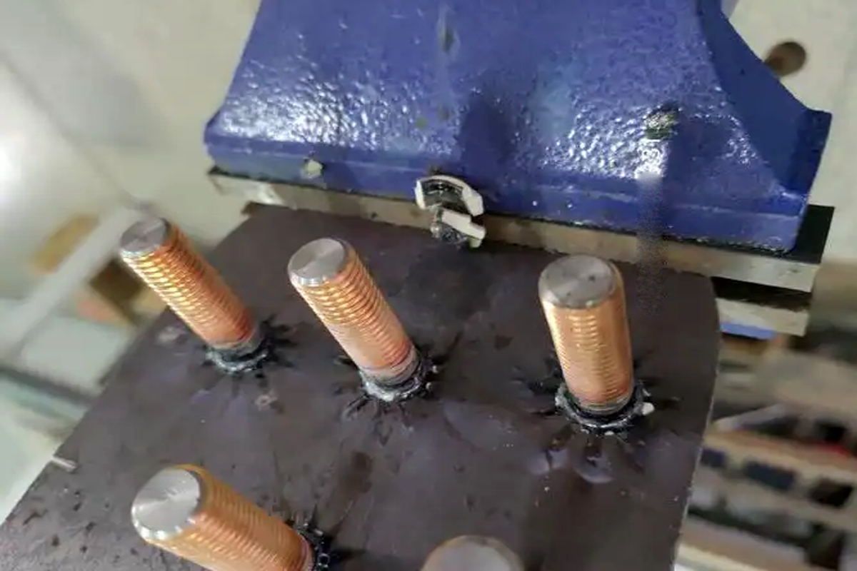
Weld Fasteners Solutions
For weld nuts, weld studs, weld screws, and custom projection-welded fastening components.
Fastener Surface Finishes & Coatings
For evaluating zinc plating, trivalent chromium zinc, zinc-nickel, zinc-aluminum, zinc-flake and other application-specific surface-treatment systems.
Fastener Fatigue Strength & Cyclic Loading
For understanding the relationship between preload, external loading, fatigue, and joint integrity.
Fastener Failure Modes & Root Cause Analysis
For investigating thread stripping, fastener fracture, loosening, deformation, coating-related issues, and other joint failures.
Self-Clinching Fasteners
For permanent threaded fastening in suitable sheet-metal applications.
Blind Rivet Nuts
For one-sided installation where rear access is unavailable.
Threaded Inserts for Plastic
For creating durable internal threads in polymer components.
High-Strength Fasteners
For applications requiring elevated mechanical performance and controlled assembly conditions.
For a torque-critical OEM project, the most efficient sourcing path is not:
RFQ → Lowest Price → Purchase Order
A more reliable engineering-to-production path is:
Engineering Drawing → Joint Requirement Review → Fastener Selection → Material Review → Surface Treatment Review → Prototype/Samples → Torque-Tension Validation → Customer Approval → Production → Inspection → Controlled Supply
Provide:
2D drawing;
3D model where available;
material requirements;
surface-treatment requirements.
Explain:
parent material;
joint loading;
installation direction;
access limitations;
assembly tool;
target torque or preload.
JUXIN FASTENERS can evaluate whether the application is better suited to:
weld nuts;
weld studs;
weld screws;
self-clinching fasteners;
blind rivet nuts;
threaded inserts;
custom screws;
bolts;
CNC-machined fasteners.
Where coating or lubrication affects the torque specification, the surface-treatment system should be considered as part of the assembly specification.
Prototype or sample parts can be evaluated before committing to mass production.
The approved material, coating, dimensions, and manufacturing process should become controlled production requirements.
Any significant change to material, coating, lubricant, supplier, or manufacturing process should be reviewed against the existing assembly specification.
K is an empirical coefficient influenced by friction and assembly conditions.
Different surface treatments can produce different friction behavior.
A lubrication change can alter the torque-preload relationship.
Excessive preload can damage the fastener or joint components.
The mating nut, weld nut, rivet nut, insert, or parent material may fail before the bolt reaches its own mechanical limit.
Torque is an indirect method of controlling preload and is highly sensitive to friction.
Torque-angle is a tightening strategy, not a universal solution.
A new coating may change friction, thread fit, corrosion behavior, or tool performance.
The complete joint should be evaluated when joint integrity is critical.
A successful laboratory result does not automatically guarantee production consistency.
It is the relationship between the rotational torque applied during tightening and the resulting axial tension or preload in the fastener.
A simplified relationship is commonly expressed as:
T = K × d × F
where K represents an empirical torque coefficient.
The actual relationship depends strongly on friction and assembly conditions.
No.
A generic K-factor can be useful for preliminary calculations, but production torque specifications should be based on the actual fastener, coating, lubrication, thread, bearing condition, and assembly process.
Lubrication generally changes friction.
At the same applied torque, a lower-friction condition can result in higher fastener tension because less torque is consumed overcoming friction.
This is why lubrication changes may require torque-tension revalidation.
No.
Increasing torque generally increases preload until other limits are reached, but excessive preload can cause fastener yielding, thread damage, joint deformation, or fracture.
The correct preload depends on the complete joint design.
Torque is rotational input.
Preload is axial tension generated in the fastener and corresponding compression in the joint.
Torque is commonly used as an indirect method for controlling preload.
Because their friction conditions may differ.
Potential causes include:
coating;
lubrication;
surface roughness;
thread condition;
bearing surface;
contamination;
manufacturing variation.
A correctly designed and installed weld nut provides a fixed, anti-rotation threaded fastening point.
However, it does not automatically guarantee a specific torque-tension relationship.
Torque performance still depends on thread condition, coating, mating fastener, joint design, weld quality, and assembly conditions.
No.
They use different installation methods and have different design requirements.
Self-clinching fasteners depend on mechanical engagement with a suitable sheet material and hole condition, while weld nuts rely on a welded attachment.
The appropriate solution depends on the parent material, production process, access, and joint requirements.
They can be used in many demanding applications, but suitability depends on the rivet-nut design, parent material, installation method, thread size, grip condition, and required assembly load.
The application should be validated rather than selected based solely on nominal thread size.
The supplier should ideally receive:
drawing;
material;
thread;
coating;
parent material;
target torque;
target preload if available;
assembly process;
annual volume;
corrosion requirements;
inspection requirements.
This allows the supplier to evaluate both the product and the production process.
If your application depends on controlled tightening torque, stable clamping force, or repeatable production assembly,
the fastener should be evaluated as part of the complete joint rather than as an isolated catalog component.
JUXIN FASTENERS can support OEM and industrial projects involving:
weld nuts;
weld studs;
weld screws;
self-clinching fasteners;
blind rivet nuts;
threaded inserts for plastic;
custom screws and bolts;
CNC-machined fasteners;
stainless steel fasteners;
high-strength fasteners;
application-specific surface treatments.
For an engineering and sourcing review, send:
2D engineering drawing;
3D model if available;
parent material;
fastener material;
thread specification;
surface treatment;
lubrication requirement;
target torque;
target preload where available;
assembly method;
annual volume;
corrosion requirements;
required inspection and compliance documentation.
Email: info@juxinfasteners.com
The recommended commercial path is:
RFQ → Engineering Review → Fastener & Material Selection → Surface Treatment Review → Samples → Validation → Production Approval → Mass Production → Quality Control → Controlled Supply
The fastener torque-tension relationship is fundamentally a friction-control problem combined with fastener and joint mechanics.
The tightening torque applied by an assembly tool is only an indirect means of generating the preload required by the joint.
The final result depends on:
Torque + Thread Friction + Bearing Friction + Coating + Lubrication + Fastener Geometry + Joint Stiffness + Material + Assembly Process
For engineers, the most important principle is:
Do not specify tightening torque independently from the fastener surface condition and joint design.
For procurement managers, the most important principle is:
Do not change fastener coating, lubrication, material, or supplier process without considering its potential effect on the existing torque specification.
For supply-chain managers and supplier development teams, the most important principle is:
A torque-critical fastener requires controlled manufacturing, documented specifications, repeatable surface treatment, validation, and change management—not simply a competitive unit price.
For OEM applications involving weld nuts, self-clinching fasteners, blind rivet nuts, threaded inserts, custom screws, bolts, or CNC-machined fastening components,
JUXIN FASTENERS can evaluate the fastening requirement from engineering design through production sourcing.
A reliable fastening program should ultimately connect:
Joint Design → Fastener Selection → Material → Coating → Friction → Preload → Assembly Validation → Production Control → Long-Term Supply
That is the foundation for repeatable joint performance in automotive, EV, industrial machinery, electrical equipment, energy infrastructure, transportation, and other demanding OEM applications.
For your next torque-critical fastening project, send your drawing, application requirements, and annual volume to info@juxinfasteners.com for an engineering and sourcing review.

Product Packaging
Packaging Standard
At Juxin Fasteners, we apply standardized export packaging to ensure product protection, traceability, and compliance with international logistics requirements.
1. Standard Export Packaging
Unless otherwise specified, all products will be packed according to our factory standard export packaging, which includes:
Moisture-resistant inner protection
Poly bag or small box packing as required
Reinforced export cartons
Clear labeling with part number, specification, batch number, and quantity
Palletizing for sea or air shipment when necessary
Our standard packaging is designed to ensure safe transportation, efficient warehousing, and long-distance international shipping.
2. Customized Packaging Options
We also provide customized packaging solutions according to customer requirements, including but not limited to:
Private labeling
Customized barcodes
Specific carton dimensions
Retail packaging
Special pallet configuration
Customer-specific marking and identification
So that you know, customized packaging may involve additional costs and extended lead time depending on the complexity of the requirements.
3. Compliance & Quality Assurance
All packaging processes are controlled under our ISO 9001 quality management system to ensure consistency, traceability, and product integrity throughout the supply chain.
Product Pictures
Contact Us
Tel.:
+86 020 8621 0320
+86 020 3121 6067
E-mail:
Technical Support:
Navigation
SEND INQUIREY