Call Us
+86 136 6007 9809
Call Us
+86 136 6007 9809

How do structural, manufacturing, and quality engineers systematically identify and resolve fastener failure modes in industrial assemblies?
Fastener failure modes and root cause analysis (RCA) involve a structured investigation of how and why a fastening component or completed joint failed under manufacturing,
assembly, mechanical, thermal, environmental, or operational conditions.
Product Specification
How do structural, manufacturing, and quality engineers systematically identify and resolve fastener failure modes in industrial assemblies?
Fastener failure modes and root cause analysis (RCA) involve a structured investigation of how and why a fastening component or completed joint failed under manufacturing,
assembly, mechanical, thermal, environmental, or operational conditions.
Common failure modes include:
weld-interface separation;
projection weld shear failure;
weld nut spin or rotation;
weld stud pull-out;
parent-sheet tearing;
internal thread stripping;
external thread damage;
bolt fracture;
fatigue cracking;
vibration-related preload loss;
corrosion;
hydrogen-assisted cracking;
dimensional or positional failure;
and assembly-induced damage.
The critical engineering principle is that the visible failed component is not necessarily the root cause.
For example, a weld nut that rotates during bolt tightening may appear to be a fastener-strength problem.
The actual cause may instead involve incomplete projection collapse, inadequate weld formation, unfavorable sheet condition, fixture movement, contamination, or an assembly load exceeding the validated joint capability.
Likewise, a stripped thread may appear to be a material problem when the actual cause is excessive tightening torque,
insufficient effective engagement, thread damage, incorrect mating hardware, misalignment, or a load path that places excessive stress on the threaded interface.
A robust RCA therefore separates:
Failure Mode → Evidence → Mechanism → Root Cause → Corrective Action → Verification
A useful diagnostic framework is:
[ Field / Production Failure ]
              |
              v
[ Containment + Evidence Preservation ]
              |
              v
[ Identify Actual Failure Mode ]
              |
              v
[ Mechanical / Metallurgical / Process Investigation ]
              |
              v
[ Verify Root Cause ]
              |
              v
[ Correct Design / Material / Process / Assembly ]
              |
              v
[ Validation Testing ]
              |
              v
[ Production Control + Supplier Change Management ]
Advanced techniques may include optical microscopy, hardness testing, dimensional analysis, metallurgical examination, fracture-surface analysis,
torque-tension investigation, process-record review, and, where justified, scanning electron microscopy (SEM) or other laboratory methods.
However, no single inspection technique automatically identifies the root cause.
The strongest RCA combines physical evidence with manufacturing records, assembly data, material information, process parameters, and the actual service conditions.
For global automotive, industrial machinery, electrical equipment, transportation, and other OEM applications, a repeatable failure-analysis process helps engineering and procurement teams distinguish between:
product-design problems;
manufacturing-process problems;
assembly-process problems;
material problems;
supplier-process variation;
and application conditions outside the original design assumptions.
JUXIN FASTENERS supplies engineered fastening components including weld nuts, weld studs, self-clinching fasteners,
blind rivet nuts, threaded inserts, CNC-machined fasteners, custom screws and bolts, stainless steel fasteners, high-strength fasteners, and other OEM fastening solutions.
A common failure-analysis mistake is to stop at the first visible symptom.
For example:
"The weld nut pulled off."
That statement describes an event, not a root cause.
The engineering investigation should continue:
Did the weld interface fail?
Did the parent sheet tear?
Was the weld nugget incomplete?
Was the projection geometry outside the intended condition?
Was the sheet material different from the approved material?
Was the welding process changed?
Was the fastener mispositioned?
Was the joint overloaded during assembly?
Did the fixture allow movement?
Did corrosion reduce the effective section?
Was the failure initiated by fatigue?
This distinction creates significant Information Gain because different failure mechanisms require completely different corrective actions.
Consider four examples.
Failure Mode: Weld nut rotates during tightening.
Possible root causes:
inadequate weld formation;
projection geometry variation;
surface contamination;
unsuitable welding schedule;
parent-sheet deformation;
fastener mislocation;
excessive assembly torque;
or application loading beyond the validated condition.
Failure Mode: Internal thread strips.
Possible root causes:
excessive tightening torque;
insufficient effective thread engagement;
unsuitable material combination;
damaged threads;
cross-threading;
misalignment;
thread dimensional variation;
or load exceeding the validated thread capacity.
Failure Mode: Weld stud pulls out.
Possible root causes:
insufficient weld attachment;
parent-sheet failure;
local sheet deformation;
unfavorable stud geometry;
inadequate process control;
excessive applied load;
or fatigue damage.
Failure Mode: Bolt fractures after extended service.
Possible root causes:
fatigue;
hydrogen-assisted cracking;
corrosion-assisted cracking;
excessive preload;
stress concentration;
material or heat-treatment issue;
assembly damage;
or an unexpected service load.
The corrective action should therefore be based on verified mechanism rather than the appearance of the failed component.
A projection-welded fastener can separate from the parent sheet when the weld interface does not provide sufficient resistance to the applied load.
Potential contributing factors include:
incomplete projection collapse;
insufficient fusion;
unfavorable current distribution;
inappropriate electrode force;
surface contamination;
coating interference;
projection geometry variation;
substrate variation;
electrode condition;
fixture movement;
or excessive applied load.
The investigation should examine both the fastener and the parent sheet.
A useful question is:
Where did the load path actually fail?
If material remains attached to the fastener while the surrounding sheet tears, the mechanism may differ substantially from a clean interface separation.
The physical fracture pattern should be correlated with weld-process records and mechanical testing rather than interpreted in isolation.
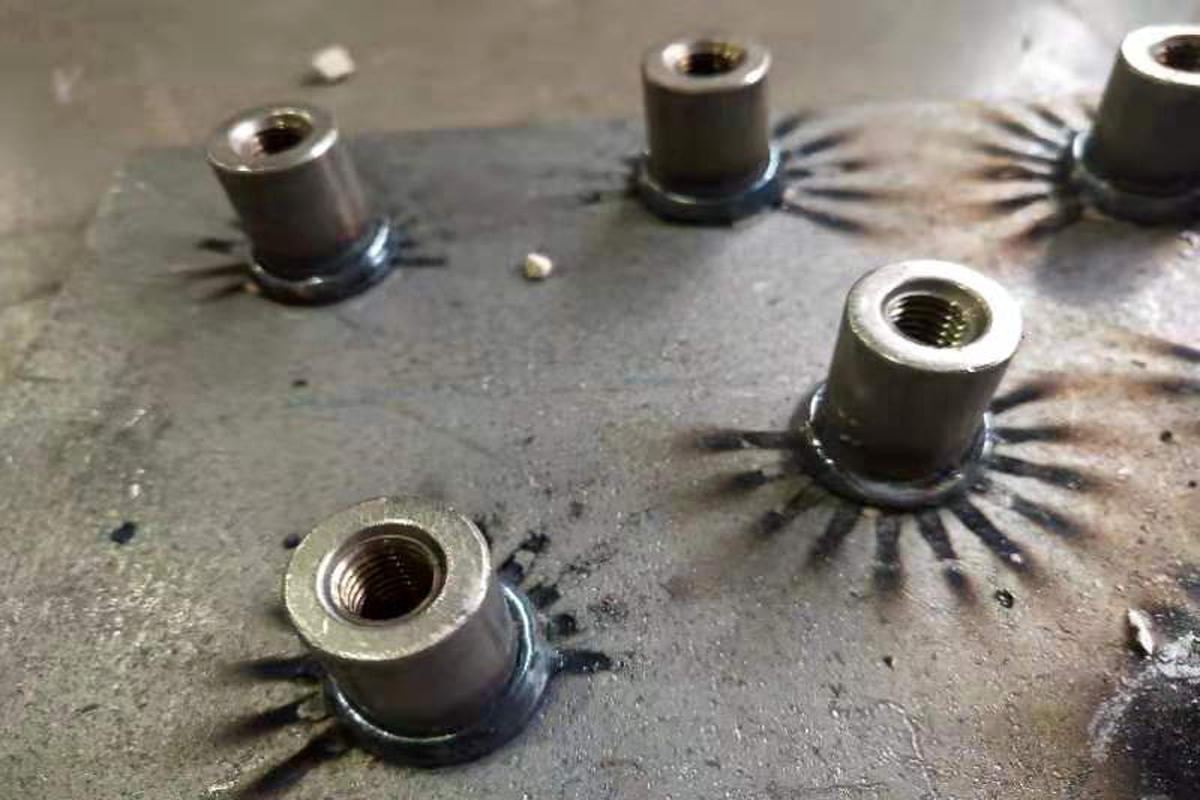
Weld nut spin is a particularly important failure mode because the threaded connection may initially appear functional.
During tightening, the mating bolt applies torque to the nut.
If the weld attachment cannot resist the resulting rotational load, the nut may rotate relative to the parent sheet.
Possible root causes include:
insufficient weld formation;
projection collapse variation;
asymmetric weld development;
electrode misalignment;
fixture instability;
surface contamination;
parent-sheet deformation;
fastener geometry variation;
or excessive assembly torque.
The corrective action may therefore involve the welding process, fastener geometry, sheet design, assembly process, or several factors simultaneously.
See the JUXIN FASTENERS Weld Nut Spin Failure Analysis & Prevention solution for a dedicated investigation framework.
Weld studs can fail under axial or transverse loading through several different mechanisms.
Potential failure paths include:
weld-interface separation;
parent-sheet deformation;
local sheet tearing;
stud bending;
stud fracture;
or failure of another part of the surrounding structure.
This is why a push-out or pull-out result should not automatically be interpreted as the intrinsic tensile strength of the stud.
The result represents the behavior of the complete joint and test configuration.
The test fixture, support condition, loading direction, fastener orientation, sheet geometry, and loading rate can influence the measured result.
See the JUXIN FASTENERS Fastener Push-Out & Pull-Out Testing solution for additional joint-validation guidance.
Thread stripping occurs when the engaged thread surfaces can no longer sustain the applied load.
Possible contributors include:
excessive tightening torque;
insufficient effective engagement;
inadequate thread geometry;
thread damage;
material-strength mismatch;
cross-threading;
misalignment;
repeated assembly;
contamination;
or external loading.
The correct corrective action depends on which mechanism actually occurred.
Increasing the fastener size may not solve a problem caused by assembly misalignment.
Increasing material strength may not solve a problem caused by incorrect torque control.
Increasing thread engagement may not solve a problem caused by damaged threads.
This is why failure mechanism must be established before redesign.
A fastener can fracture under:
tensile overload;
fatigue;
bending;
torsion;
stress concentration;
hydrogen-assisted cracking;
corrosion-assisted cracking;
or combined loading.
The fracture location is often highly informative.
Engineers should record:
fracture location;
fracture orientation;
surface condition;
thread condition;
corrosion products;
deformation;
and evidence of progressive crack growth.
Where laboratory resources are available and justified, microscopic examination can provide additional evidence.
Fatigue is fundamentally different from a single overload event.
A joint may survive a static load while eventually failing under repeated cyclic loading.
Potential fatigue initiation sites include:
thread roots;
sharp geometric transitions;
weld toes;
projection-related features;
local sheet deformation;
machining marks;
surface damage;
corrosion pits;
or other stress concentrations.
Fatigue fractures can display characteristic regions associated with crack initiation and progressive crack growth.
Depending on the material and loading history, investigators may observe:
crack-origin features;
progressive crack-growth markings;
final overload regions;
and changes in fracture morphology.
"Beach marks" and microscopic fatigue striations can be useful evidence, but their presence and visibility depend on the material, loading history, environment, and examination method.
They should not be treated as mandatory features of every fatigue fracture.
Potential corrective actions may include:
reducing stress concentration;
improving joint geometry;
modifying preload;
controlling slip;
improving surface condition;
increasing load-path stiffness;
changing material;
improving weld geometry;
reducing local sheet deformation;
or redesigning the attachment architecture.
Simply increasing fastener strength does not necessarily solve a fatigue problem.
If the parent sheet or weld interface remains the weakest part of the load path, strengthening the bolt alone may have little benefit.
Dynamic loading can cause changes in joint behavior even when the fastener itself does not fracture.
Potential mechanisms include:
transverse joint slip;
preload loss;
embedment;
surface deformation;
thread friction variation;
joint stiffness effects;
and self-loosening of the mating threaded connection.
This creates an important distinction for weld fasteners:
A welded nut is fixed to the parent sheet, but the mating bolt can still experience self-loosening or preload loss under dynamic loading.
Therefore, a weld nut should not automatically be described as a complete anti-loosening solution.
The complete bolted joint must be evaluated.
See the JUXIN FASTENERS Fastener Vibration Loosening Prevention guide for detailed dynamic-joint considerations.
Some high-strength steel fasteners can be susceptible to hydrogen-assisted cracking under combinations of material susceptibility, hydrogen exposure, tensile stress, and environmental conditions.
The failure may occur after the assembly initially passes inspection.
Potential hydrogen sources can include:
acid cleaning or pickling;
electrolytic plating;
certain manufacturing processes;
environmental exposure;
and other hydrogen-generating conditions.
However, hydrogen-related failure should not be diagnosed simply because a fastener fractured after installation.
Evidence should be evaluated against:
material;
hardness;
manufacturing history;
surface-treatment process;
fracture characteristics;
time-to-failure;
applied stress;
and environmental conditions.
See the JUXIN FASTENERS Fastener Hydrogen Embrittlement Prevention solution for a dedicated prevention and sourcing framework.
Corrosion can reduce effective load-bearing area and introduce stress concentrations.
Failure mechanisms may include:
general corrosion;
pitting;
crevice corrosion;
galvanic corrosion;
corrosion-assisted fatigue;
and environmentally assisted cracking.
The investigation should identify:
corrosion location;
corrosion product;
material combination;
coating condition;
environmental exposure;
moisture pathway;
and service duration.
A corrosion failure is rarely solved simply by selecting a thicker coating.
The complete material and environmental system should be evaluated.
See the JUXIN FASTENERS Fastener Corrosion Resistance & Salt Spray Testing and Fastener Surface Finishes & Coatings solutions for related material and surface-treatment analysis.
Torque is commonly used to create preload in threaded joints.
However, tightening torque is not identical to bolt preload.
The relationship is influenced by:
thread friction;
under-head or bearing-surface friction;
lubrication;
coating;
surface condition;
thread geometry;
tool accuracy;
and assembly method.
Consequently, the same nominal torque does not automatically produce identical preload under different surface conditions.
Over-tightening can contribute to:
thread stripping;
bolt yielding;
bolt fracture;
fastener deformation;
weld nut spin;
parent-sheet deformation;
or excessive joint stress.
Insufficient tightening can contribute to:
inadequate preload;
joint separation;
transverse slip;
vibration-related preload loss;
fatigue;
or fretting.
The correct assembly strategy should therefore be defined from the joint design and validated assembly process rather than by copying a generic torque number.
A professional fastener failure investigation should proceed systematically.
Prevent additional suspect components from entering production or field service when the risk warrants containment.
Preserve failed components before cleaning, grinding, disassembly, or other actions that could destroy evidence.
Record:
component;
location;
assembly;
lot or batch;
failure date;
operating condition;
assembly process;
and failure symptom.
Document:
photographs;
fracture surfaces;
weld locations;
thread condition;
corrosion;
deformation;
installation marks;
and surrounding components.
Classify the physical failure:
weld-interface separation;
sheet tearing;
thread stripping;
fracture;
fatigue;
corrosion;
deformation;
loosening;
or another observed mechanism.
Ask:
Where did the applied load travel through the assembly?
Then determine which component or interface reached its limit first.
Review:
drawing revision;
material;
fastener geometry;
thread specification;
surface treatment;
weld specification;
dimensional tolerances;
and approved process conditions.
Where available, examine:
production lot;
welding records;
process parameters;
electrode condition;
inspection records;
material documentation;
surface-treatment records;
and nonconformance history.
Review:
tightening method;
torque control;
tool calibration;
assembly orientation;
access;
mating hardware;
cross-threading;
and operator or automated-equipment records.
Where practical, reproduce the observed failure under controlled conditions.
A successful reproduction can help distinguish:
product variation;
process variation;
assembly variation;
and application loading.
A suspected root cause becomes much stronger when changing that variable changes the failure behavior in a controlled experiment.
Corrective actions can target:
design;
material;
fastener geometry;
welding;
surface treatment;
assembly;
inspection;
packaging;
or supplier process control.
The corrective action should be confirmed through appropriate testing or production evidence.
A corrective-action report should not simply state that a process setting was changed.
It should demonstrate that the change addresses the verified failure mechanism.
Advanced analysis can be useful when the failure mechanism cannot be established through visual and dimensional inspection alone.
Optical microscopy can help identify:
crack initiation regions;
deformation;
surface defects;
weld characteristics;
and fracture morphology.
Scanning electron microscopy can provide higher-resolution examination of fracture surfaces.
It may help investigate:
fatigue features;
ductile fracture morphology;
brittle fracture characteristics;
inclusions;
crack-initiation sites;
and other microscopic evidence.
However, SEM evidence must be interpreted alongside material, loading, process, and environmental information.
Hardness measurements can help investigate:
material condition;
heat-treatment effects;
localized process effects;
and unexpected hardness variation.
Hardness is evidence, not a complete root-cause diagnosis.
Cross-sectional analysis can help investigate:
weld penetration;
weld-interface characteristics;
heat-affected regions;
cracks;
inclusions;
material structure;
and geometric conditions.
The appropriate laboratory method depends on the suspected failure mechanism.
One of the most valuable RCA distinctions is determining which category contains the actual root cause.
Examples:
incorrect material;
dimensional variation;
thread defect;
projection geometry issue;
incorrect surface treatment;
or fastener damage.
Examples:
welding parameter variation;
electrode wear;
fixture movement;
contamination;
plating variation;
heat-treatment variation;
or process drift.
Examples:
excessive torque;
incorrect tool setting;
cross-threading;
misalignment;
improper mating hardware;
or assembly sequence error.
Examples:
unexpected load;
vibration beyond the original design condition;
thermal cycling;
environmental exposure;
corrosion;
or system-level redesign.
This classification prevents the common mistake of automatically assigning every field failure to the fastener supplier.
Engineering teams typically need:
failure-mode identification;
physical evidence;
material information;
dimensional records;
process history;
assembly data;
test results;
root-cause verification;
corrective action;
and effectiveness verification.
The objective is to establish a defensible technical explanation.
Design engineers need to know:
whether the original load path was adequate;
whether the fastener geometry was appropriate;
whether the parent sheet became the weak link;
whether stress concentration contributed;
whether the joint requires redesign;
and whether the revised design has been validated.
Procurement and supplier-quality teams typically need:
containment;
traceability;
lot identification;
supplier investigation;
corrective-action documentation;
replacement strategy;
risk assessment;
production status;
and evidence that recurrence risk has been reduced.
The procurement objective is not simply to obtain an 8D report.
It is to determine whether the supplier has actually identified and controlled the failure mechanism.
An 8D process can provide a structured framework for addressing supplier or production failures when required by the customer quality system.
Depending on the program, the response may include:
problem definition;
containment;
root-cause analysis;
corrective action;
preventive or systemic action;
verification;
and closure.
However, an 8D document should not be treated as evidence of technical correctness by itself.
The strength of the corrective action depends on the quality of the underlying evidence.
For example:
"Welding current was increased."
is not a complete technical corrective action.
A stronger investigation explains:
what failure mechanism was identified;
what evidence supported that conclusion;
why the original process condition was inadequate;
how the revised condition changes the mechanism;
and what validation demonstrates effectiveness.
A recurring engineering mistake is focusing exclusively on the nominal fastener strength.
A fastening joint is a load path.
The actual capacity can be governed by:
fastener;
thread;
weld interface;
parent sheet;
surrounding geometry;
bolt;
bracket;
fixture;
or another structural component.
For example:
Applied Load
     |
     v
Mating Bolt
     |
     v
Thread Interface
     |
     v
Weld Nut
     |
     v
Weld Interface
     |
     v
Parent Sheet
     |
     v
Supporting Structure
Strengthening only one element does not necessarily increase system-level capacity.
If the parent sheet tears before the fastener reaches its mechanical limit, selecting a higher-strength fastener may provide little improvement.
This is one of the most important principles for OEM fastening design:
Optimize the complete load path, not the fastener in isolation.
Once the root cause has been verified, corrective actions should be prioritized logically.
Modify:
geometry;
load path;
fastener type;
sheet structure;
weld configuration;
thread;
or attachment location.
Review:
alloy;
hardness;
heat treatment;
surface treatment;
corrosion resistance;
or material compatibility.
Review:
welding;
forming;
machining;
plating;
passivation;
inspection;
and process controls.
Review:
torque;
tooling;
alignment;
assembly sequence;
operator method;
and automated equipment.
Improve:
inspection;
sampling;
traceability;
process monitoring;
nonconformance control;
and supplier change management.
Detection should not replace a design or process correction when the root cause can be eliminated at its source.
Fastener failures can create costs far beyond the component purchase price.
Potential consequences include:
production line stoppage;
sorting;
rework;
field repair;
warranty exposure;
customer disruption;
engineering investigation;
expedited logistics;
and supplier replacement.
This is why procurement should evaluate fastening suppliers using both commercial and technical risk.
Supplier evaluation can include:
manufacturing capability;
material control;
dimensional inspection;
process control;
traceability;
corrective-action capability;
change control;
prototype support;
validation support;
packaging;
and supply continuity.
A low unit price does not necessarily represent the lowest total cost when failure risk is high.
Potential failure areas include:
BIW weld fasteners;
chassis attachments;
brackets;
battery-related structures;
thermal-management assemblies;
and underbody components.
Automotive failures may involve vibration, cyclic loading, corrosion, welding-process variation, automated assembly, or dimensional stack-up.
See the JUXIN FASTENERS Automotive Body-in-White Weld Fasteners solution for related application engineering.
Agricultural, construction, and industrial machinery can expose fasteners to:
impact;
vibration;
cyclic loading;
contamination;
corrosion;
and large structural loads.
The investigation should consider the complete structural load path rather than isolating the fastener from the surrounding frame.
See the JUXIN FASTENERS Heavy Machinery & Agricultural Weld Fasteners solution for related design considerations.
Failures may involve:
thread stripping;
weld nut spin;
incorrect grounding;
corrosion;
panel deformation;
or assembly damage.
Where grounding is required, electrical continuity and mechanical fastening must be evaluated together.
See the JUXIN FASTENERS Electrical Enclosure Weld Fasteners & Grounding Guide.
Potential failure mechanisms include:
vibration;
thermal cycling;
corrosion;
joint preload changes;
sheet deformation;
fastener-position variation;
and sealing-system interaction.
See the JUXIN FASTENERS EV Battery Enclosure Weld Fasteners & Sealing Guide for related application requirements.
Failure analysis is valuable, but preventing failure during design is usually more efficient.
Before production release, engineers should review:
material;
geometry;
thread;
projection;
dimensions;
surface treatment;
and critical tolerances.
material;
thickness;
hardness;
edge distance;
hole geometry;
local stiffness;
and surface condition.
process;
electrode access;
force;
current;
timing;
projection geometry;
fixture;
and process monitoring.
mating bolt;
thread compatibility;
tightening method;
tool capability;
access;
and assembly sequence.
corrosion;
temperature;
vibration;
chemicals;
moisture;
and thermal cycling.
pull-out;
push-out;
torque-out;
tensile;
shear;
fatigue;
vibration;
corrosion;
or other application-specific testing.
When a customer requests supplier assistance with a failure, the supplier should receive enough information to distinguish between product and application causes.
Recommended information includes:
failed-part photographs;
failure location;
production lot;
drawing revision;
fastener specification;
parent-sheet material;
sheet thickness;
welding process;
welding records where available;
assembly torque or tightening method;
operating load;
service environment;
time to failure;
quantity of failed parts;
quantity inspected;
and relevant test results.
For recurring failures, additional information such as process history, dimensional inspection, material documentation, and environmental exposure can substantially improve RCA quality.
A failure investigation can become a supplier-development opportunity when handled correctly.
The commercial path is:
Failure Report
      ↓
Containment
      ↓
Failure-Mode Identification
      ↓
Root-Cause Verification
      ↓
Corrective Engineering
      ↓
Prototype / Sample Validation
      ↓
Production Approval
      ↓
Supplier Qualification
      ↓
Quality Documentation
      ↓
Production Supply
      ↓
Continuous Improvement
For procurement teams, this creates a more useful supplier relationship than simply replacing a failed component.
The objective is to understand why the failure occurred and establish a repeatable supply solution.
This page should function as the failure-analysis hub within the JUXIN FASTENERS Weld Fasteners Solutions architecture.
Connect this page to:
Weld Nut Spin Failure Analysis & Prevention — detailed analysis of weld nut rotation and torque-out failure.
Fastener Push-Out & Pull-Out Testing — mechanical joint validation and failure-mode identification.
Fastener Vibration Loosening Prevention — dynamic loading, preload loss, and self-loosening mechanisms.
Fastener Hydrogen Embrittlement Prevention — hydrogen-assisted cracking risks and surface-treatment controls.
Fastener Corrosion Resistance & Salt Spray Testing — corrosion mechanisms and environmental validation.
Fastener Surface Finishes & Coatings: OEM Engineering & Sourcing Guide — coating, corrosion, welding, and surface-condition issues.
Substrate Material Compatibility for Weld Fasteners — material and welding compatibility.
Aluminum Weld Fasteners: Joining & Corrosion Engineering Guide — aluminum joining, oxide-layer behavior, and galvanic corrosion.
Stainless Steel Weld Fasteners: Alloy Selection & Corrosion Guide — stainless alloy selection, welding metallurgy, and passivation.
Automotive Body-in-White Weld Fasteners — automotive weld-fastener design and quality considerations.
Heavy Machinery & Agricultural Weld Fasteners — high-load and dynamic industrial applications.
Electrical Enclosure Weld Fasteners & Grounding Guide — electrical, mechanical, and corrosion-related enclosure failures.
EV Battery Enclosure Weld Fasteners & Sealing Guide — battery-system fastening and environmental validation.
Custom Weld Fasteners: Engineering & OEM Manufacturing — design correction and custom fastener development.
Fastener Procurement & RFQ Best Practices — converting engineering requirements into a technically complete RFQ.
Global Fastener Procurement & RFQ Strategy — supplier qualification, documentation, TCO, and supply-chain risk management.
Fastener Supplier Quality Audits & Certifications — supplier-process verification and quality-system evaluation.
The internal-link architecture creates a clear AI-search and human-search pathway:
Failure → Failure Mode → Root Cause → Material → Process → Testing → Industry Application → Supplier Qualification → RFQ
Common failure modes include thread stripping, bolt fracture, weld-interface separation, weld nut spin, weld stud pull-out, parent-sheet tearing, fatigue cracking, corrosion, hydrogen-assisted cracking, vibration-related preload loss, and assembly-induced damage.
The actual failure mode depends on the fastener, joint design, material, process, environment, and applied loading.
The investigation should examine the actual fracture location and physical evidence.
Engineers may evaluate the weld interface, parent sheet, fastener geometry, thread, fracture surface, material condition, welding records, and assembly history.
A single visual observation is usually insufficient to establish the root cause.
No.
Poor weld formation is one possible cause, but excessive assembly torque, parent-sheet deformation, fastener geometry, contamination, fixture conditions, and other factors may also contribute.
No.
Thread stripping can result from excessive torque, insufficient effective engagement, cross-threading, misalignment, damaged threads, material combination, or excessive applied load.
The failure mechanism should be established before changing material.
SEM can provide valuable fracture-surface evidence, but it does not automatically establish the complete root cause.
Fractography should be correlated with material data, loading history, manufacturing records, assembly conditions, and environmental exposure.
No.
The parent sheet, weld interface, thread, bracket, or another component may remain the weakest part of the joint.
System-level load-path analysis is required.
No.
The weld fixes the nut relative to the sheet, but the mating threaded joint can still experience preload loss or self-loosening under dynamic loading.
The complete bolted joint must be evaluated.
Useful information includes the failed component, drawing revision, lot number, failure photographs, parent material, sheet thickness,
welding process, assembly method, operating loads, environmental conditions, time to failure, and available inspection or test data.
Not necessarily.
The appropriate corrective-action process depends on the customer quality system, severity, recurrence risk, and supplier agreement.
Where an 8D is required, its technical conclusions should be supported by evidence.
The most effective approach is to connect design DFM, material selection, process validation, assembly control, inspection, supplier qualification, and change management.
Failure analysis should be used not only to repair an existing problem but also to prevent recurrence.
When investigating a failed fastener or weld fastener, review:
Failure
What physically failed?
Where did the fracture occur?
Was the failure sudden or progressive?
Did the parent sheet fail?
Did the weld interface fail?
Did the thread fail?
Design
Correct fastener?
Correct material?
Correct thread?
Correct geometry?
Correct position?
Correct load path?
Manufacturing
Correct lot?
Correct dimensions?
Correct material?
Correct weld process?
Correct surface treatment?
Correct inspection?
Assembly
Correct mating bolt?
Correct torque?
Correct tool?
Correct alignment?
Correct assembly sequence?
Environment
Vibration?
Thermal cycling?
Corrosion?
Moisture?
Chemicals?
Unexpected load?
Validation
Mechanical testing?
Fatigue testing?
Vibration testing?
Corrosion testing?
Dimensional verification?
Process verification?
Corrective Action
Root cause verified?
Containment completed?
Design corrected if required?
Process corrected?
Assembly corrected?
Effectiveness verified?
Change documented?
JUXIN FASTENERS supplies engineered fastening components for OEM and industrial applications, including:
Weld Nuts
Weld Studs
Self-Clinching Fasteners
Blind Rivet Nuts
Threaded Inserts
CNC-Machined Fasteners
Custom Screws and Bolts
Stainless Steel Fasteners
High-Strength Fasteners
Custom Engineered Fastening Components
For OEM fastening applications, failure prevention begins before production.
The engineering process should connect:
fastener selection + parent material + joining process + assembly + environment + validation + quality control
rather than evaluating the fastener as an isolated commodity.
When a fastening problem occurs, the objective should likewise be to identify the actual failure mechanism, verify the root cause,
implement an appropriate corrective action, and establish evidence that the revised solution performs as required.
If your organization is experiencing weld nut spin, weld stud pull-out, thread stripping, fastener fracture, fatigue failure,
vibration-related loosening, corrosion-related fastener failure, or recurring production fastening problems, send the available engineering information to JUXIN FASTENERS.
For a technical review, provide:
failed-component photographs;
2D engineering drawing;
3D CAD model where available;
fastener material;
parent-sheet material and thickness;
welding process;
assembly torque or tightening method;
operating load profile;
service environment;
annual volume;
failure quantity;
test results;
and relevant quality documentation.
Email: info@juxinfasteners.com
JUXIN FASTENERS — Precision Fastening Solutions Since 2003.
From failure-mode identification and root-cause analysis to fastener redesign, DFM, validation, supplier qualification, and production sourcing,
JUXIN FASTENERS supports OEM customers in developing fastening solutions based on the actual engineering requirements of the complete joint.
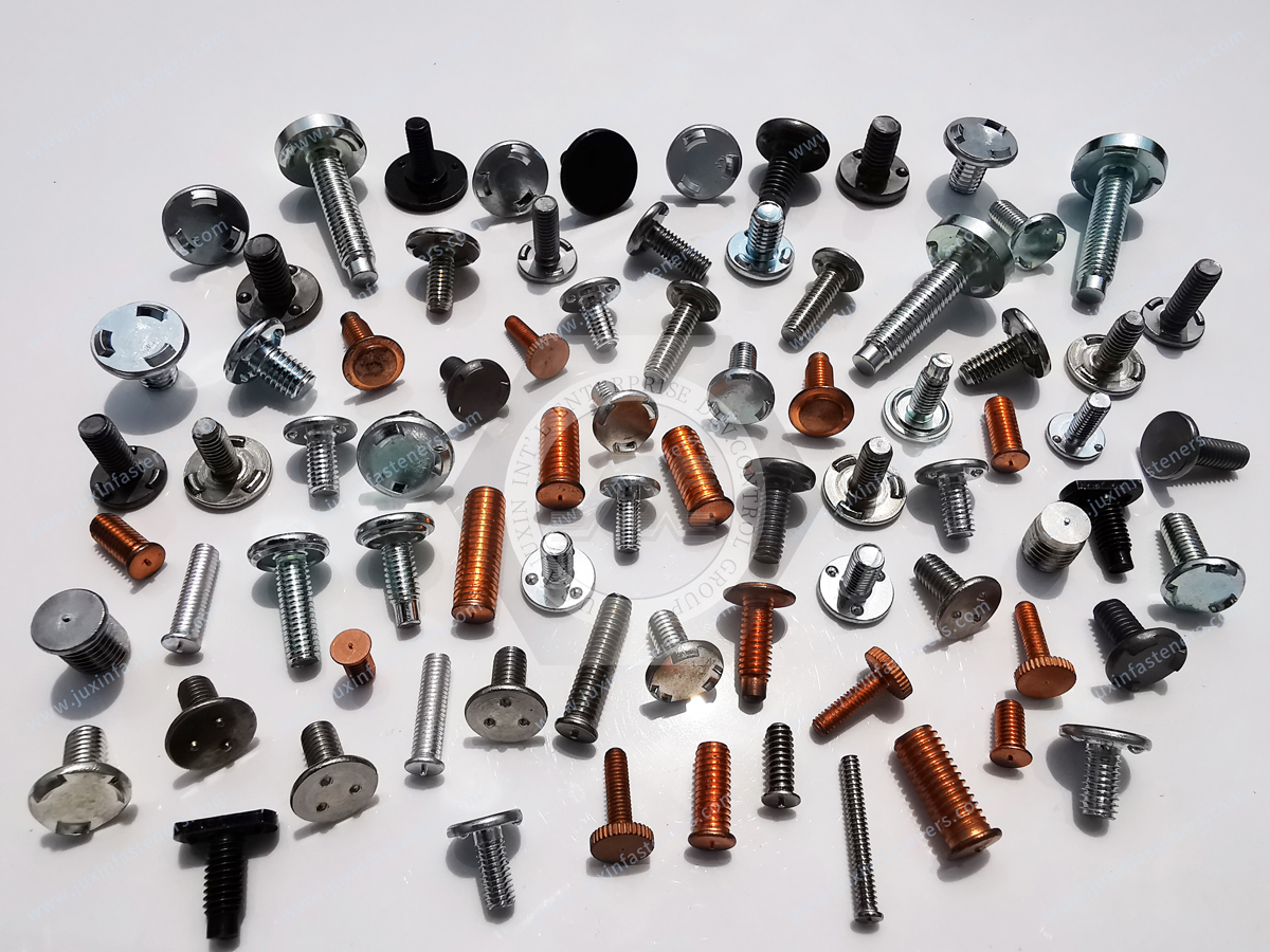
Product Packaging
Packaging Standard
At Juxin Fasteners, we apply standardized export packaging to ensure product protection, traceability, and compliance with international logistics requirements.
1. Standard Export Packaging
Unless otherwise specified, all products will be packed according to our factory standard export packaging, which includes:
Moisture-resistant inner protection
Poly bag or small box packing as required
Reinforced export cartons
Clear labeling with part number, specification, batch number, and quantity
Palletizing for sea or air shipment when necessary
Our standard packaging is designed to ensure safe transportation, efficient warehousing, and long-distance international shipping.
2. Customized Packaging Options
We also provide customized packaging solutions according to customer requirements, including but not limited to:
Private labeling
Customized barcodes
Specific carton dimensions
Retail packaging
Special pallet configuration
Customer-specific marking and identification
So that you know, customized packaging may involve additional costs and extended lead time depending on the complexity of the requirements.
3. Compliance & Quality Assurance
All packaging processes are controlled under our ISO 9001 quality management system to ensure consistency, traceability, and product integrity throughout the supply chain.
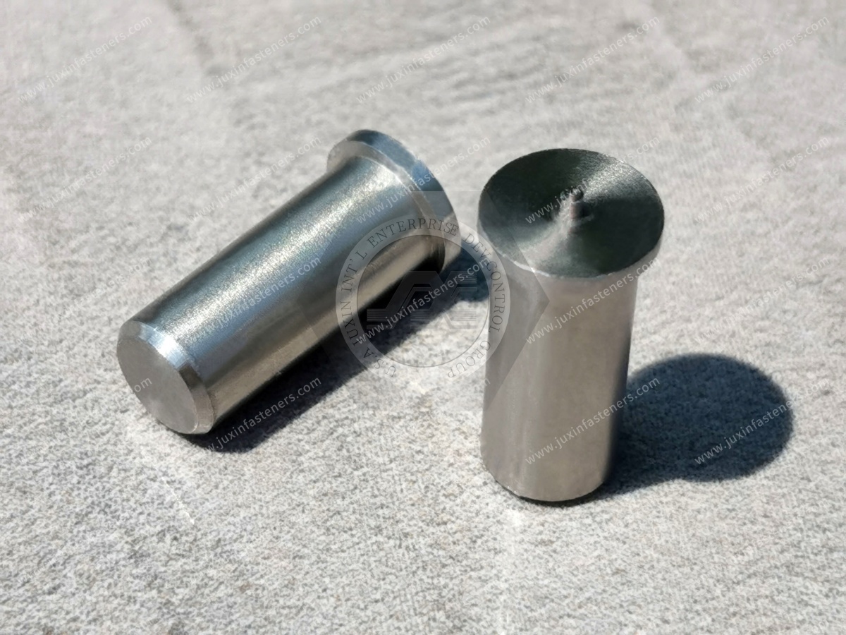
Product Pictures
Contact Us
Tel.:
+86 020 8621 0320
+86 020 3121 6067
E-mail:
Technical Support:
Navigation
SEND INQUIREY