Call Us
+86 136 6007 9809
Call Us
+86 136 6007 9809

When should engineers specify ISO 21670 hexagon flange weld nuts instead of square weld nuts?
ISO 21670 hexagon flange weld nuts, with corresponding dimensional references such as DIN 977 where applicable,
are designed for applications where the combination of hexagonal nut geometry, integrated flange,
and projection-welding features provides the required threaded attachment and bearing interface for the sheet-metal assembly.
Product Specification
When should engineers specify ISO 21670 hexagon flange weld nuts instead of square weld nuts?
ISO 21670 hexagon flange weld nuts, with corresponding dimensional references such as DIN 977 where applicable,
are designed for applications where the combination of hexagonal nut geometry, integrated flange,
and projection-welding features provides the required threaded attachment and bearing interface for the sheet-metal assembly.
The integrated flange can increase the effective bearing area between the fastener and parent sheet. This can be useful where local contact stress,
panel deformation, seating stability, or load distribution are important design considerations.
However, the presence of a flange does not automatically make a hexagon flange weld nut stronger than a square weld nut in every application.
The correct selection depends on:
fastener geometry
flange diameter
projection configuration
parent-sheet material
sheet thickness
panel stiffness
applied bolt preload
tensile and shear loading
local bearing stress
weld-interface capacity
welding access
surface condition
coating system
assembly torque
downstream coating process
environmental requirements
customer-specific automotive specifications
A simplified cross-section can be represented as:
             [ Hexagon Flange Weld Nut ]
                _____________
              /             \
             /  Threaded     \
            |      Bore       |
             \_______________/
              \_____________/
              Integrated Flange
                 ●       ●
                 Projection
================================================
                 Base Metal
During resistance projection welding, the projections concentrate electrical resistance and localized heat at the intended welding locations.
As the projections collapse under electrode force, localized fusion occurs between the weld nut and the parent sheet.
The resulting joint is therefore influenced by both fastener geometry and welding-process development.
Hexagon flange weld nuts can be considered for automotive Body-in-White (BIW), chassis-related assemblies, brackets, sheet-metal structures, electrical equipment,
industrial machinery, and other applications requiring a permanent threaded attachment point.
In automotive production, applications may include reinforcement panels, brackets, mounting structures, door-related components, seat-related structures, chassis components,
and other assemblies where the customer drawing and validation specification permit this type of welded threaded fastener.
For high-load or safety-related applications, the fastener should be evaluated as part of the complete joint rather than selected solely from the nominal nut property class.
JUXIN FASTENERS supports OEM sourcing and engineering evaluation of hexagon flange weld nuts, including dimensional configuration,
material, surface treatment, projection-welding requirements, thread protection, and application-specific quality requirements.
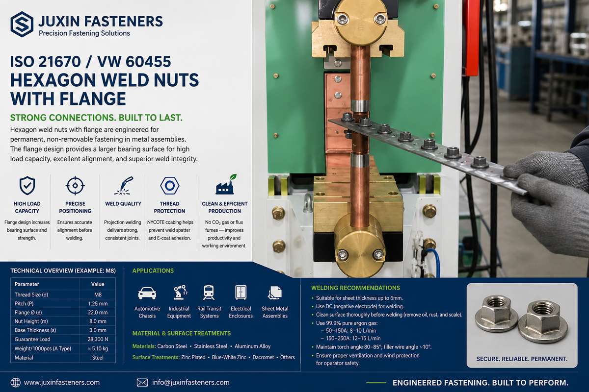
When sheet metal is relatively thin, highly formed, locally flexible, or subjected to significant bolt preload, the bearing area between the fastener and parent sheet can become an important design consideration.
A standard weld nut without an enlarged flange may concentrate the reaction force over a relatively limited area.
An integrated flange increases the effective seating footprint.
The basic contact-stress relationship can be represented as:
σ = F / A
where:
σ = average contact stress
F = applied force
A = effective bearing area
Increasing the effective bearing area can reduce average local contact stress under the same applied force.
This can help engineers evaluate the risk of:
local panel indentation
sheet deformation
bearing failure
distortion around the fastener
loss of seating stability
However, this equation is a simplified engineering relationship.
Actual sheet-metal behavior is affected by:
panel stiffness
sheet thickness
fastener geometry
flange geometry
hole configuration
load eccentricity
bolt preload
local reinforcement
material strength
forming history
Therefore, the flange should not be treated as an automatic guarantee against panel deformation.
The flange can distribute the reaction force over a larger region of the parent sheet.
This may be particularly useful when the fastener is installed on:
thin sheet metal
formed panels
reinforcement brackets
stamped automotive structures
equipment enclosures
mounting plates
locally flexible sheet-metal components
The engineer should evaluate whether the flange actually engages an adequate area of the parent sheet.
A larger flange does not automatically produce a stronger joint if the surrounding panel remains the weakest component.
The complete load path should therefore be considered:
Bolt → Thread → Weld Nut → Weld Interface → Parent Sheet → Reinforcement / Structure
Failure at any point in this path can limit the overall assembly performance.
Hexagon and square weld nuts can both provide useful anti-rotation characteristics after welding.
The selection should be based on the actual application rather than assuming one geometry is universally superior.
A hexagon flange weld nut may offer advantages where:
the flange area is beneficial
surrounding clearance favors hexagonal geometry
a particular automated feeding system is designed around the part
the customer drawing specifies the geometry
the flange-to-panel interface provides useful load distribution
A square weld nut may be preferred where:
square geometry provides the required positional characteristics
anti-rotation requirements favor the design
existing tooling is optimized for the square configuration
the customer specification identifies a square weld nut
The appropriate geometry is therefore an engineering and manufacturing decision.
Weld nuts can be specified with different mechanical property classes depending on the product configuration and application requirement.
The mechanical property of the nut should be evaluated against:
mating bolt strength
required preload
installation torque
service load
thread engagement
joint stiffness
fatigue loading
expected failure mode
The property class of the weld nut should not be considered independently from the mating bolt and complete joint.
For example, specifying a higher property class for the nut does not automatically increase the capacity of the welded attachment if the parent sheet or weld interface remains the limiting component.
Resistance projection welding introduces a localized thermal cycle.
The welding process can produce a heat-affected region around the weld interface.
The actual thermal response depends on:
fastener material
parent-sheet material
electrical resistance
welding current
current duration
electrode force
projection geometry
electrode configuration
surface condition
welding sequence
Potential engineering effects include:
local hardness changes
microstructural transformation
residual stress
local softening or hardening
weld-interface variation
parent-sheet deformation
Therefore, the mechanical property of the nut and the weldability of the complete fastener-to-sheet combination must be considered together.
Certain automotive OEM specifications, including documents such as VW 60455, may define requirements for particular fastener, joint, or tightening applications.
However, such specifications should be interpreted according to the specific vehicle program, component application, revision, and customer drawing.
They should not be converted into universal rules such as:
Every weld nut must have a higher property class than the bolt.
The actual requirement should be verified from the applicable OEM documentation.
For unquenched/tempered fasteners with property classes at or below a specified level, the complete joint should be evaluated for the expected loading and failure modes according to the customer engineering requirement.
During resistance welding, small quantities of molten or partially molten metal can be expelled from the weld interface.
Depending on welding conditions and fastener geometry, weld spatter can potentially enter the threaded bore.
This can create downstream problems such as:
difficult bolt engagement
thread contamination
assembly torque variation
thread damage
rework
increased cleaning requirements
For this reason, some automotive and industrial manufacturing processes use dedicated thread-protection systems.
NYCOTE or another specified polymeric thread-protection system may be used where the customer manufacturing process requires protection of the internal thread during welding and subsequent coating operations.
The objective can include reducing:
weld-spatter contamination
coating ingress
e-coat accumulation
paint contamination
assembly interference
However, NYCOTE should not be presented as an automatic requirement for every ISO 21670 weld nut.
The appropriate thread-protection method depends on:
welding process
coating process
fastener geometry
thread specification
required cleanliness
assembly method
customer production standards
Automotive components may undergo downstream processes such as pretreatment, cathodic electro-deposition, rinsing, curing, and painting.
These processes can introduce coating material into threaded areas.
If the internal thread must remain functional after coating, the production system may require:
temporary thread protection
masking
specialized coating-resistant treatments
post-coating thread cleaning
controlled coating deposition
customer-specific thread-protection systems
The correct solution must therefore be evaluated across the complete manufacturing sequence.
For high-performance structural joints, the tightening strategy can be as important as the nominal fastener strength.
Depending on the application, an OEM may specify:
torque-controlled tightening
angle-controlled tightening
torque-angle tightening
yield-controlled tightening
other defined preload-control strategies
The selected method must correspond to the bolt, joint stiffness, friction condition, fastener system, and customer specification.
Under specific yield-controlled tightening protocols, including protocols associated with particular automotive specifications such as VW 60455, the installation preload may be regulated within a defined range.
The supplied technical data provides the following example:
M8 Bolt, Class 10.0: approximately 29,000 N to 36,000 N
This should be treated as a specific engineering example for the applicable tightening protocol, not as a universal preload range for every M8 Class 10.0 bolt or every ISO 21670 weld-nut application.
Actual tightening parameters must be verified against:
bolt specification
joint design
friction condition
thread condition
lubrication
washer configuration
joint stiffness
tightening method
OEM/customer specification
The supplied technical reference also provides the following example for an M8 Class 8.8 bolt:
approximately 19,500 N to 26,000 N
Again, this is an example of an application-specific engineering threshold rather than a universal installation preload.
The actual preload target should be established from the applicable joint design and tightening specification.
Bolt preload transfers force into the joint and creates reaction forces at the weld nut and surrounding sheet.
The engineer should therefore evaluate:
flange bearing area
parent-sheet stiffness
weld-interface capacity
nut mechanical properties
bolt mechanical properties
thread condition
tightening method
installation torque
joint relaxation
service loading
The objective is not simply to maximize tightening force.
The objective is to establish a controlled joint preload that is compatible with the complete assembly.
Hexagon flange weld nuts can be considered for various automotive sheet-metal structures.
Potential applications include:
reinforcement panels
brackets
mounting structures
door-related assemblies
seat-related structures
interior mounting points
body attachment points
The selection depends on the vehicle architecture and customer-specific requirements.
The fastener must be compatible with:
stamped panel geometry
robotic welding
feeder systems
electrode access
downstream coating
dimensional requirements
final assembly tooling
Weld nuts can also be used in chassis-related sheet-metal structures and brackets where permanent threaded attachment points are required.
Potential loads can include:
tensile loading
shear loading
bending
vibration
cyclic fatigue
For these applications, the flange can help distribute local bearing loads, but it does not eliminate the need to evaluate the parent sheet and welded interface.
Door-related structures can experience repeated dynamic loading and localized torque.
A weld nut may therefore be integrated into reinforcement structures or mounting brackets.
The engineering evaluation should include:
bolt preload
hinge reaction forces
local panel stiffness
weld quality
nut rotation resistance
fatigue loading
corrosion protection
The flange may help manage local bearing stress, but actual performance depends on the complete joint design.
The projections are critical to the resistance welding process.
Their:
number
location
height
geometry
consistency
affect current concentration and heat generation.
Projection geometry should therefore be controlled according to the applicable product drawing and welding process.
Electrode access should be evaluated before releasing the part design.
Potential interference can occur near:
panel flanges
reinforcement ribs
formed sections
adjacent components
narrow channels
boxed structures
A fastener may be dimensionally correct but difficult to weld consistently if the electrode cannot approach the intended welding location correctly.
Before welding, the joining surfaces should be controlled for:
oil
grease
dirt
oxides
mill scale
uncontrolled coatings
foreign particles
The goal is consistent electrical and mechanical contact during the welding process.
Excessive heat input or unsuitable welding conditions can cause local sheet deformation.
The process should therefore be developed to balance:
welding current
electrode force
welding duration
projection geometry
material combination
electrode configuration
sheet thickness
The goal should be repeatable weld quality without unacceptable panel distortion, rather than an absolute claim of zero distortion.
Surface treatment should be selected according to the final environmental requirement.
Potential systems include:
zinc plating
zinc-nickel alloy coating
Dacromet-type zinc-aluminum flake systems
temporary protective oil
downstream e-coating systems
other customer-specified corrosion protection
The coating decision should consider both corrosion performance and manufacturing compatibility.
Important questions include:
Can the coating tolerate the welding process?
Does it affect electrical contact resistance?
Is the coating applied before or after welding?
Does it affect thread protection?
Does it interfere with e-coating?
Is additional masking required?
How will coating thickness affect thread function?
What corrosion test method applies?
Procurement teams should avoid an RFQ that simply states:
“ISO 21670 M8 flange weld nut.”
A more useful OEM RFQ should define the complete technical requirement.
standard reference
applicable standard revision
thread size
thread specification
nut geometry
flange dimensions
projection configuration
property class
material
surface treatment
thread protection
parent-sheet material
sheet thickness
welding method
welding equipment
electrode configuration
assembly torque
required preload
operating environment
temperature exposure
corrosion requirement
dimensional inspection
thread inspection
material verification where required
weld validation
torque-out testing
push-out testing
tensile/shear testing where required
surface-treatment verification
coating inspection
traceability requirements
prototype quantity
annual usage
forecast
production volume
automated feeding requirements
packaging
delivery location
production ramp-up schedule
The selection should be driven by engineering function rather than simply by the nominal standard.
Consider an ISO 21670-type hexagon flange weld nut when:
increased bearing area is beneficial
flange geometry fits the panel
the customer drawing specifies the configuration
automated feeding is compatible
welding access is available
the load path benefits from the geometry
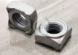
Consider a DIN 928 square weld nut when:
square geometry is required
anti-rotation characteristics suit the application
panel clearance favors the square configuration
existing production tooling supports the geometry
the customer specification identifies DIN 928
Neither configuration is universally superior.
The best selection is the one that satisfies the mechanical, welding, dimensional, assembly, corrosion, and production requirements simultaneously.
The flange can increase bearing area, but the parent sheet or weld interface may still control joint capacity.
Automotive specifications must be interpreted according to the applicable customer and component requirement.
The supplied M8 preload examples are specific engineering references and must not be applied to every joint without checking the applicable tightening specification.
Thread protection is process-specific.
A fastener that welds correctly may still create thread-function problems after downstream coating.
The surrounding sheet can become the limiting failure component.
Before production release, review:
Applicable ISO/DIN reference confirmed
Standard revision confirmed
Thread size confirmed
Thread tolerance/specification confirmed
Flange geometry confirmed
Projection geometry confirmed
Mechanical property class confirmed
Material specification confirmed
Parent-sheet material identified
Sheet thickness identified
Welding process defined
Electrode access confirmed
Fastener orientation confirmed
Hole geometry reviewed
Edge distance reviewed
Bearing area reviewed
Assembly torque defined
Preload requirement defined where applicable
Thread protection requirement defined
Surface treatment defined
Downstream e-coating process reviewed
Weld validation defined
Corrosion validation defined
Packaging and feeding requirements defined
Customer-specific automotive specifications reviewed
The correct weld nut cannot be selected by looking only at the fastener catalog.
The engineering team should evaluate the interaction between:
Fastener Geometry + Material + Projection Design + Parent Sheet + Welding Process + Surface Treatment + Thread Protection + Tightening Strategy + Assembly Environment
JUXIN FASTENERS can support OEM and industrial sourcing discussions involving:
ISO 21670-type hexagon flange weld nuts
DIN-referenced flange weld nut configurations
DIN 928 square weld nuts
metric thread requirements
property-class requirements
weldable steel selection
projection-welding compatibility
thread protection
surface treatment
automotive BIW applications
chassis-related sheet-metal applications
custom weld fastener requirements
prototype development
production sourcing
inspection requirements
packaging and automated feeding
Early engineering review can help identify potential conflicts between the fastener, welding equipment, coating sequence, and final assembly process before production tooling is finalized.
DIN 928 Square Weld Nuts Engineering Guide
For comparison of square weld nut geometry, mechanical-property considerations, welding preparation, and automotive applications.
Weld Nut Spin Failure Analysis & Prevention
For weld-interface failure, rotation, projection collapse, welding-process variation, and joint design.
Custom Weld Fasteners: Engineering & OEM Manufacturing
For applications where standard weld-nut geometry does not fully satisfy the required assembly or manufacturing conditions.
Fastener Surface Finishes & Coatings
For evaluating zinc, zinc-nickel, Dacromet-type systems, welding compatibility, thread protection, and corrosion requirements.
Fastener Procurement & RFQ Best Practices
For preparing drawings, material specifications, welding requirements, annual usage forecasts, inspection requirements, and OEM sourcing packages.
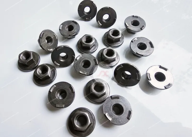
An ISO 21670 hexagon flange weld nut is a hexagonal-bodied weld nut configuration incorporating a flange and welding projections for resistance welding to a suitable sheet-metal substrate.
The exact dimensions, material, property class, projection geometry, and surface treatment should be confirmed against the applicable standard reference and product specification.
The primary geometric difference is the integrated flange.
The flange can increase the effective bearing area and may help distribute local reaction forces over a larger region of the parent sheet.
However, the actual engineering benefit depends on the sheet material, thickness, stiffness, load path, fastener geometry, and joint design.
Not automatically.
The two geometries have different configurations and may offer different advantages depending on:
bearing area
anti-rotation behavior
panel geometry
welding access
assembly requirements
load path
production tooling
The correct choice is application-specific.
NYCOTE or another specified thread-protection treatment can be used to protect internal threads from weld spatter and downstream coating contamination.
It is not automatically required for every weld nut application.
They can be used where the geometry, material, welding process, coating system, and customer requirements are compatible.
Automotive applications should be evaluated according to the applicable OEM drawing and validation requirements.
Yield-controlled tightening is a tightening strategy in which the bolt is intentionally tightened according to a defined relationship with its elastic/plastic behavior to achieve a controlled joint preload.
The exact procedure is application- and specification-dependent.
No.
These are specific engineering examples from the supplied technical reference.
Actual preload depends on the bolt property class, joint design, friction condition, tightening method, lubrication, washer configuration, joint stiffness, and applicable customer specification.
No.
A larger flange can reduce average bearing stress by increasing effective bearing area, but the parent sheet can still deform depending on its thickness, strength, stiffness, geometry, and applied load.
A complete RFQ should include:
standard reference
drawing
thread specification
material
property class
surface treatment
thread protection
parent-sheet material
sheet thickness
welding process
tightening requirements
annual volume
quality requirements
packaging requirements
A 2D engineering drawing and 3D CAD model are particularly useful for application-specific requirements.
If you are sourcing ISO 21670 / DIN-referenced hexagon flange weld nuts for automotive BIW, chassis structures, sheet-metal assemblies,
industrial machinery, electrical equipment, or other OEM applications, send your engineering requirements to JUXIN FASTENERS.
Please include:
2D engineering drawing
3D CAD model when available
thread specification
mechanical property requirement
material requirement
flange and projection requirements
surface-treatment requirement
thread-protection requirement
parent-sheet material
sheet thickness
welding process
tightening/preload requirements
annual volume
inspection requirements
packaging requirements
Email: info@juxinfasteners.com
JUXIN FASTENERS provides OEM weld fastener sourcing and engineering support for standardized and application-specific fastening requirements.
Precision Fastening Solutions Since 2003.
Product Packaging
Packaging Standard
At Juxin Fasteners, we apply standardized export packaging to ensure product protection, traceability, and compliance with international logistics requirements.
1. Standard Export Packaging
Unless otherwise specified, all products will be packed according to our factory standard export packaging, which includes:
Moisture-resistant inner protection
Poly bag or small box packing as required
Reinforced export cartons
Clear labeling with part number, specification, batch number, and quantity
Palletizing for sea or air shipment when necessary
Our standard packaging is designed to ensure safe transportation, efficient warehousing, and long-distance international shipping.
2. Customized Packaging Options
We also provide customized packaging solutions according to customer requirements, including but not limited to:
Private labeling
Customized barcodes
Specific carton dimensions
Retail packaging
Special pallet configuration
Customer-specific marking and identification
So that you know, customized packaging may involve additional costs and extended lead time depending on the complexity of the requirements.
3. Compliance & Quality Assurance
All packaging processes are controlled under our ISO 9001 quality management system to ensure consistency, traceability, and product integrity throughout the supply chain.
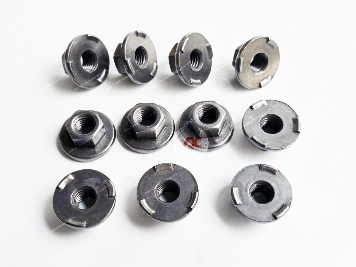
Product Pictures
Contact Us
Tel.:
+86 020 8621 0320
+86 020 3121 6067
E-mail:
Technical Support:
Navigation
SEND INQUIREY