Call Us
+86 136 6007 9809
Call Us
+86 136 6007 9809

What are projection weld studs and how do they function in sheet metal assemblies?
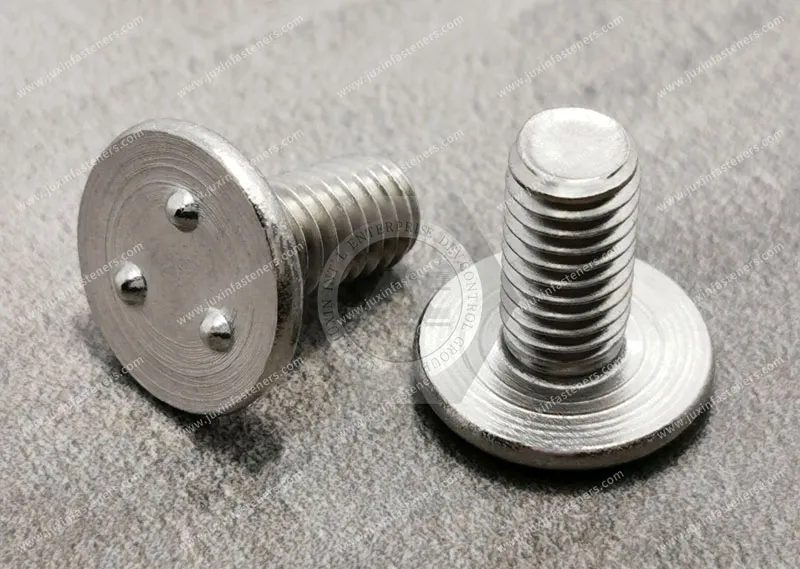
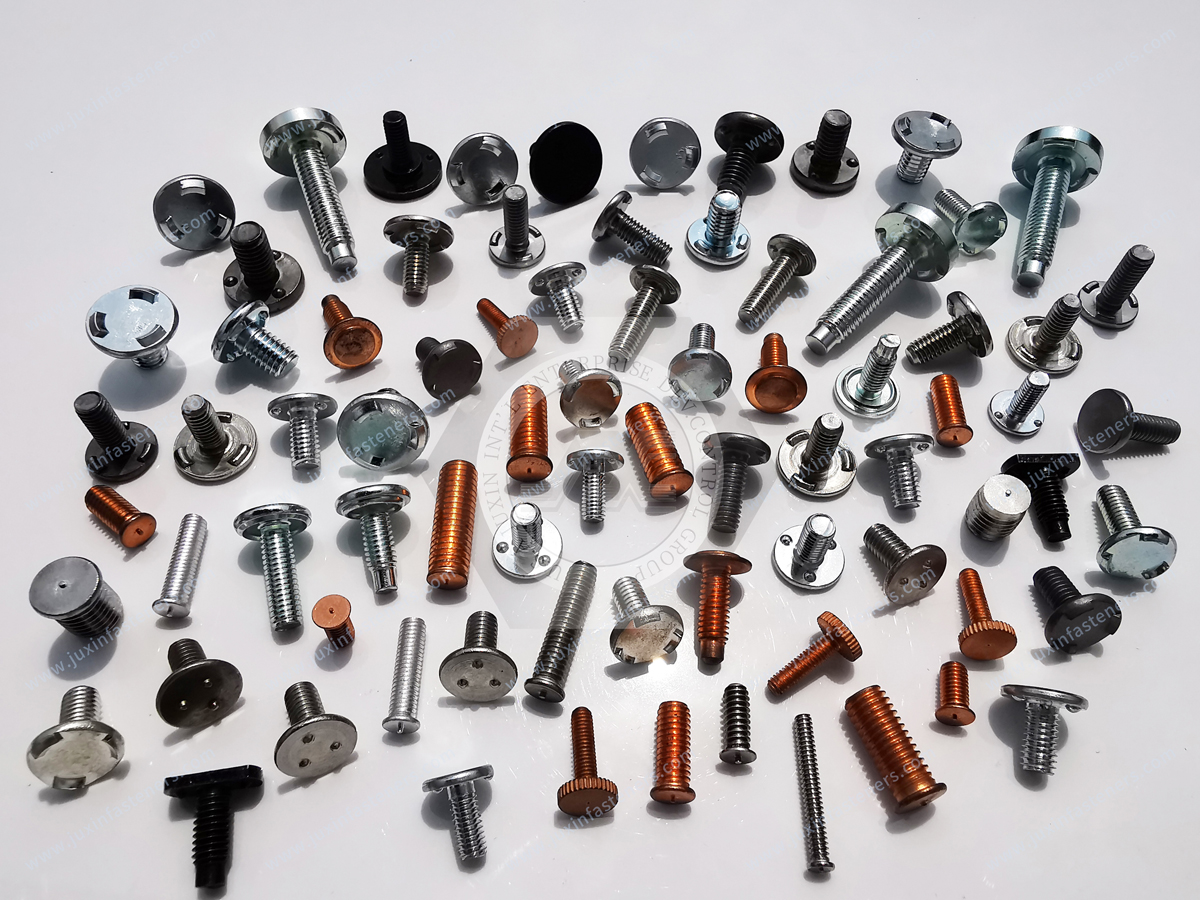
Projection weld studs are specialized threaded fasteners featuring engineered welding projections, such as annular rings or discrete projection points, on the stud head or flange.
These projections create localized contact areas during resistance projection welding.
Electrical resistance and current density are concentrated at these intended contact points,
generating localized heat that softens and collapses the projections while forming a fusion weld nugget between the fastener and the parent sheet.
Product Specification
What are projection weld studs and how do they function in sheet metal assemblies?
Projection weld studs are specialized threaded fasteners featuring engineered welding projections, such as annular rings or discrete projection points, on the stud head or flange.
These projections create localized contact areas during resistance projection welding.
Electrical resistance and current density are concentrated at these intended contact points,
generating localized heat that softens and collapses the projections while forming a fusion weld nugget between the fastener and the parent sheet.
The basic principle can be represented as:
              [ Weld Stud Head / Flange ]
             /     Projection      \
            /       /    \           \
           /_______/______\___________\
                    ↓
===================================================  Parent Sheet
                  Weld Interface
During the welding cycle, electrode force brings the stud and sheet into controlled contact.
Welding current passes through the assembly, and heat is generated according to the resistance-heating relationship commonly expressed as:
Q = I²Rt
where electrical current, electrical resistance, and the effective welding time all contribute to heat generation.
The practical welding result, however, is not determined by the equation alone.
Electrode force, projection geometry, material resistivity, sheet thickness, surface condition, current path,
welding sequence, electrode configuration, and equipment capability all influence the final weld.
Unlike conventional arc stud welding, resistance projection welding uses intentionally formed projections to establish localized electrical and mechanical contact before and during the weld cycle.
This allows the weld location to be integrated into a stamped or fabricated sheet-metal component without requiring a conventional threaded hole and separate mechanical fastener installation.
Automotive and industrial OEMs may specify projection weld studs when they need a permanent threaded attachment point on a panel, bracket, reinforcement, enclosure, frame, or other sheet-metal component.
Typical applications can include:
Automotive body-in-white structures
Interior reinforcement brackets
Chassis and frame-related components
Electrical and control enclosures
HVAC equipment
Industrial machinery
Sheet-metal cabinets
Mounting brackets
Cable and harness attachment points
Grounding or bonding attachment points where the complete electrical design permits their use
JUXIN FASTENERS can support projection weld stud sourcing by reviewing the stud geometry, substrate material, welding process,
thread requirements, surface treatment, application loads, production volume, and quality requirements together rather than treating the weld stud as an isolated commodity component.
The correct engineering question is therefore not simply:
“Which projection weld stud is strongest?”
It is:
“Which stud geometry, material, projection configuration, parent sheet, welding process, and validation method will produce a repeatable attachment point for the intended application?”
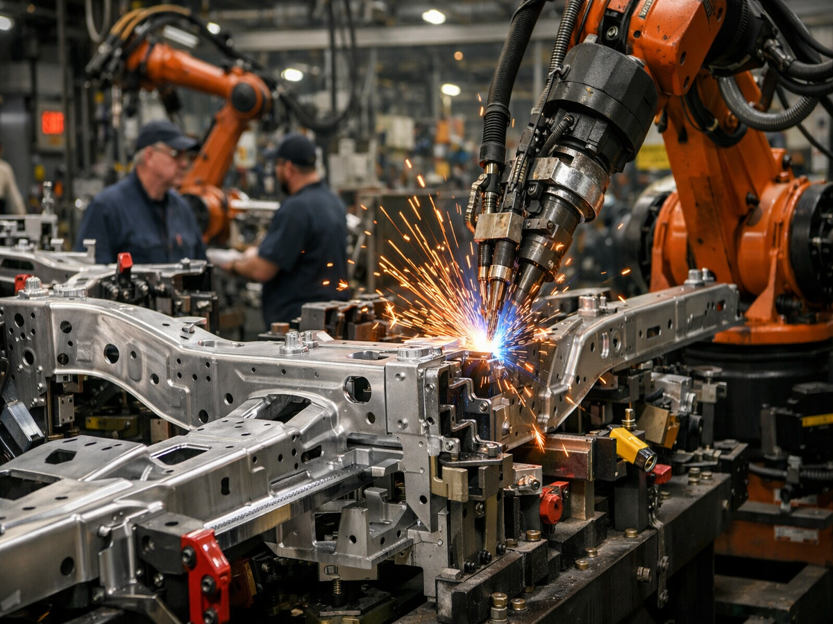
Projection geometry is one of the most important design features distinguishing a resistance projection weld stud from a conventional threaded fastener.
The projection is intentionally designed to control where electrical contact initially occurs and where welding heat is concentrated.
Unlike conventional stud welding processes that use an arc to create the weld interface,
resistance projection welding depends on electrical resistance within the contacting materials and the controlled concentration of current through the projection region.
The simplified relationship is:
Q = I²Rt
This relationship explains why projection geometry matters.
A projection creates a localized current path. As welding current passes through the reduced contact area, localized heating occurs.
As the projection heats and collapses under electrode force, the contact area changes and the weld interface develops.
In production, the objective is not simply to maximize heat.
The process must establish an appropriate balance between:
Welding current
Electrode force
Welding time
Projection geometry
Fastener material
Parent sheet material
Sheet thickness
Surface condition
Electrode configuration
Electrical resistance
Heat dissipation into surrounding material
Too little effective heat or insufficient projection collapse can contribute to incomplete fusion or inadequate weld development.
Excessive heat can contribute to:
Expulsion
Spatter
Excessive indentation
Local sheet distortion
Electrode contamination
Surface damage
Unwanted changes to the parent material
For this reason, welding parameters should be developed for the specific combination of fastener, substrate, equipment, and joint configuration rather than copied as universal settings.
An annular or ring-type projection creates a continuous intended contact path around the stud interface.
This geometry can be useful when the engineering objective includes:
A distributed weld interface
Controlled load transfer around the fastener
Defined weld geometry
Reduced dependence on a small number of isolated contact points
Integration with specific sealing or enclosure architectures
However, an annular projection must not automatically be described as a hermetic seal.
A continuous or closed weld interface can support a sealing architecture, but whether the finished assembly is actually leak-tight depends on the entire interface, including:
Weld continuity
Surface condition
Parent sheet geometry
Welding process capability
Defects or discontinuities
Subsequent machining or forming
Seal design
Assembly configuration
Leak-testing method and acceptance criteria
Likewise, an annular projection does not automatically make an enclosure IP67 or IP68 compliant.
Those are assembly-level ingress requirements that must be demonstrated through the applicable enclosure design and validation process.
Discrete projections create multiple localized contact points between the weld stud and the parent sheet.
They can be designed to distribute the welding interface across several intended locations while maintaining localized current concentration during the initial phase of welding.
Potential advantages include:
Controlled initial contact
Defined weld locations
Distributed load transfer
Compatibility with specific stud geometries
Repeatable welding behavior when properly developed
The number, shape, height, spacing, and location of projections should be considered part of the engineered fastener design.
There is no single projection geometry that is universally superior.
The correct design depends on the fastener dimensions, parent material, sheet thickness, electrode access, required mechanical performance, production equipment, and application environment.
A projection weld stud does not function independently from the sheet metal to which it is welded.
The final joint is a system consisting of:
Weld Stud + Projection Geometry + Parent Sheet + Welding Process + Electrode System + Assembly Load
Therefore, selecting the stud based only on thread size is insufficient for many OEM applications.
The structural integrity of a welded stud joint depends heavily on the relationship between the stud and the parent sheet.
Important variables include:
Parent sheet material
Fastener material
Electrical resistivity
Thermal conductivity
Sheet thickness
Surface treatment
Coating condition
Welding current path
Electrode force
Projection design
Required mechanical load
Gemini's original reference to approximately 0.8 mm to 4.0 mm sheet thickness can be useful as an example of the type of sheet-metal range encountered in some automotive applications,
but it should not be treated as a universal thickness specification for projection weld studs.
A suitable thickness range must be established from the actual fastener design, substrate, welding equipment, and customer requirements.
If the parent sheet is very thin relative to the stud and projection geometry, the welding process may create localized deformation or excessive thermal concentration.
Potential issues include:
Burn-through or expulsion
Excessive indentation
Local panel distortion
Inadequate weld development
Parent-sheet tearing
Heat-affected deformation
Conversely, a substantially thicker substrate can change the thermal balance and current distribution and may require a different process window.
The weld stud and parent sheet should be evaluated as a metallurgical system.
Low-carbon steel is widely encountered in resistance-welded sheet-metal assemblies, but the suitability of a particular fastener material depends on the actual parent material and welding process.
Material selection should consider:
Carbon content
Alloying elements
Hardenability
Electrical resistance
Thermal behavior
Surface coating
Welding cycle
Heat-affected region
Required mechanical performance
The statement that the stud composition must simply “match” the parent sheet is too simplistic.
A weld stud does not necessarily have to be chemically identical to the parent sheet.
Dissimilar material combinations can sometimes be engineered successfully, but they require evaluation of electrical, thermal, metallurgical, mechanical, and corrosion behavior.
Although projection weld studs can eliminate the need for a conventional threaded hole, the parent sheet may still contain:
Clearance holes
Formed features
Access openings
Pilot features
Locating features
Reinforcement geometry
The required geometry depends on the specific weld stud design.
Fastener location should also be evaluated relative to:
Sheet edges
Existing holes
Bends
Embossments
Flanges
Adjacent welds
Other fasteners
Forming features
There is no universal edge-distance rule that can safely replace application-specific DFM review.
When the stud is positioned too close to an edge or another opening, local stiffness and current distribution can change.
The resulting weld may therefore behave differently from a stud located in a more constrained area of the panel.
The orientation of the threaded stud affects both welding and downstream assembly.
Engineers should evaluate:
Electrode approach direction
Stud projection direction
Mating component access
Nut installation access
Tool clearance
Harness clearance
Washer or bracket placement
Robotic tool accessibility
Serviceability
A stud can have excellent mechanical properties and still be unsuitable if the assembly tool cannot reach the thread reliably.
Projection weld studs are frequently considered for high-volume sheet-metal manufacturing because the fastener can become a permanent part of the panel before downstream assembly.
However, automation performance depends on the complete production system.
For automated welding, procurement and manufacturing teams should evaluate:
Fastener orientation
Feeding method
Part presentation
Electrode access
Panel location accuracy
Welding sequence
Part detection
Stud presence verification
Weld monitoring
Downstream handling
A weld stud that performs well in laboratory testing may still require development before it is suitable for automated production.
Stud geometry affects how parts behave in:
Vibratory bowl feeders
Linear tracks
Hoppers
Escapements
Robotic feeding systems
Pick-and-place equipment
Important factors include:
Head diameter
Stud length
Flange shape
Projection geometry
Center of gravity
Surface finish
Part-to-part friction
Packaging configuration
Packaging and feeder design should therefore be considered together during OEM development.
The sequence of weld operations can affect:
Panel deformation
Heat accumulation
Accessibility
Electrical current paths
Electrode life
Production takt
Surface appearance
For complex BIW or fabricated assemblies, welding sequence should be considered during process development rather than after the fastener has already been selected.
A projection weld stud should be validated according to the actual load cases and failure modes expected in the application.
Mechanical testing is not simply a matter of proving that the weld can withstand one generic force.
The correct test method depends on:
Stud geometry
Parent sheet
Welding process
Load direction
Assembly function
Customer specification
Applicable test standard
Required failure mode
Push-out testing evaluates the resistance of the welded stud assembly to a defined loading condition that attempts to displace the stud relative to the sheet.
The test can help identify:
Weld-interface failure
Parent-sheet deformation
Local sheet tear-out
Projection weld weakness
Excessive panel deformation
The measured value should be interpreted together with the observed failure mode.
A higher numerical force is not automatically better if the test setup or failure mode does not represent the actual application.
Pull-out or tensile testing evaluates the joint under an axial loading condition.
Depending on the design, the limiting failure mechanism may involve:
Weld-interface separation
Parent sheet failure
Stud deformation
Local sheet yielding
Combined deformation of the panel and fastener
For structural applications, the design team should establish the required load capacity using the applicable engineering design practice rather than applying a universal safety factor.
Torque-out testing is relevant when the threaded stud will experience rotational loading during nut installation or service.
The test can evaluate whether the welded attachment remains stable while the mating threaded component is tightened.
Torque-out performance depends on:
Weld geometry
Weld area
Stud head design
Projection configuration
Parent sheet properties
Weld quality
Installation torque
Joint geometry
Therefore, a universal torque-out value should not be assigned to every projection weld stud.
Mechanical test results become much more useful when the failure mode is recorded.
For example:
Weld-interface failure
The weld attachment separates at or near the welded interface.
Parent-sheet failure
The sheet deforms or tears around the welded stud.
Stud deformation
The stud itself yields or bends before the attachment fails.
Local panel deformation
The stud remains attached while the surrounding sheet undergoes excessive deformation.
These different failure modes have different engineering implications.
Welding parameters are among the most sensitive parts of projection weld stud development.
The main process variables can include:
Welding current
Welding time
Electrode force
Squeeze time
Hold time
Projection geometry
Electrode geometry
Electrical contact resistance
Sheet material
Fastener material
Surface condition
Increasing current generally increases the electrical heating contribution because heat generation follows the relationship:
Q = I²Rt
However, simply increasing current is not a universal method for improving weld strength.
Excessive current can contribute to:
Expulsion
Spatter
Electrode contamination
Surface damage
Excessive indentation
Local overheating
Insufficient current can contribute to:
Incomplete projection collapse
Inadequate fusion
Weak weld development
High process variability
The appropriate current must therefore be developed for the actual fastener and substrate combination.
Electrode force affects contact resistance, projection deformation, and heat distribution.
If force is too low, the contact condition may become unstable.
If force is too high, projections may collapse prematurely or the electrical and thermal conditions may shift away from the intended process window.
Therefore, electrode force should be treated as a controlled process variable rather than a fixed universal number.
Welding time affects how long the electrical heating process acts on the joint.
Shorter or longer welding times may alter:
Heat distribution
Projection collapse
Nugget development
Expulsion behavior
Heat-affected region
The correct welding time depends on the specific welding system and joint configuration.
Surface condition is particularly important in resistance welding.
Potential variables include:
Oil
Scale
Oxides
Plating
Coatings
Contamination
Storage corrosion
Handling residue
A controlled and repeatable surface condition is generally preferable to an uncontrolled one.
For coated fasteners, the coating must be evaluated for its effect on electrical contact, welding behavior, corrosion performance, and downstream processing.
The projection is not simply a small feature added to the fastener.
It is part of the welding system.
Projection dimensions influence:
Initial contact area
Current concentration
Mechanical collapse
Heat generation
Weld-interface development
Electrode force response
The appropriate geometry depends on the fastener size, material, parent sheet, and welding process.
Universal projection dimensions should therefore be avoided unless they are explicitly defined by a recognized product standard or controlled JUXIN FASTENERS product specification.
The intended result is development of a fusion weld nugget between the fastener and the parent sheet.
Nugget quality depends on the interaction between:
Current + Resistance + Time + Force + Projection Geometry + Materials + Surface Condition
A visual inspection alone may not be sufficient to establish weld quality.
Depending on the application, validation may include:
Destructive testing
Cross-section analysis
Mechanical testing
Process monitoring
Dimensional inspection
Weld-current monitoring
Electrode condition monitoring
Material and surface treatment should be selected together with the welding sequence.
Controlled steel surfaces can provide a predictable welding interface when the welding process is developed around the actual surface condition.
Temporary corrosion protection may be used where required, but any oil or protective treatment must be evaluated for its effect on resistance welding.
Zinc coatings may provide corrosion protection but can also affect welding behavior.
The engineering team should consider:
Coating thickness
Electrical resistance
Coating breakdown during welding
Electrode contamination
Welding fumes
Post-weld corrosion protection
The correct coating sequence depends on the manufacturing process.
Higher-performance coating systems may be considered where corrosion requirements are demanding.
However, a coating should not be selected solely because it has a higher laboratory corrosion-test result.
The complete system should consider:
Welding compatibility
Corrosion environment
Electrical requirements
Thread function
Downstream coating
Cost
Customer specifications

Projection weld studs can provide permanent threaded attachment points in a wide range of sheet-metal applications.
Potential BIW applications include:
Brackets
Reinforcement panels
Instrument-panel structures
Interior attachment points
Door-related structures
Seat-related structures
Harness mounting points
Trim attachment points
The suitability of a weld stud depends on its location and function.
A stud used for a non-structural bracket should not automatically be treated as equivalent to a stud used in a safety-critical structural application.
Safety-related automotive applications require detailed customer drawings, material specifications, welding validation, and application-specific testing.
Projection weld studs may also be considered for selected chassis or structural sheet-metal applications.
The design team should evaluate:
Static loads
Dynamic loads
Fatigue
Vibration
Shock
Environmental exposure
Parent-sheet deformation
Weld fatigue behavior
The fastener's nominal tensile strength alone does not define the capacity of the completed joint.
Projection weld studs can provide permanent mounting points for:
Brackets
Grounding components
Cable management
Control equipment
Internal panels
Electrical hardware
For grounding or bonding applications, electrical continuity must be validated as a complete interface. Coatings, contact surfaces, corrosion, assembly force, and applicable electrical requirements all matter.
A weld stud does not automatically provide a compliant grounding path simply because it is welded to a metal panel.
Design for manufacturability should be addressed before production tooling is finalized.
Ensure that welding electrodes can reach the intended weld location without interference from:
Flanges
Bends
Adjacent panels
Brackets
Other weld studs
Tooling
Fixtures
Avoid placing weld studs in locations where local geometry creates unpredictable contact or excessive deformation.
Review:
Panel curvature
Embossments
Drawn features
Reinforcement ribs
Sheet edges
Holes
Bends
The thread should remain accessible for the downstream mating component.
Review:
Nut access
Tool clearance
Washer clearance
Thread engagement
Adjacent component interference
Assembly direction
Where multiple weld studs are installed on the same component, evaluate whether welding order can create unwanted heat accumulation or panel distortion.
Define whether the fastener is:
Welded in a pre-coated condition
Welded before the panel coating process
Protected locally
Coated after welding
Used with a downstream e-coating or painting operation
The sequence must be compatible with both welding and corrosion requirements.
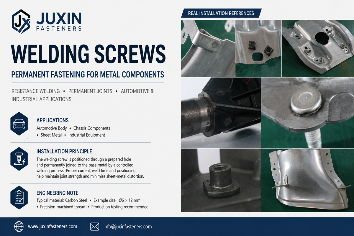
The selection between a projection weld stud and a conventional mechanical attachment should be based on the complete manufacturing process.
Projection welding can eliminate a separate threaded-hole preparation or post-weld mechanical fastening operation in suitable applications.
Potential manufacturing benefits include:
Integrated threaded attachment
Reduced separate fastener installation
Compatibility with automated welding
Consistent fastener location
Reduced assembly operations
However, welding also introduces its own process requirements:
Welding equipment
Electrode access
Process development
Weld inspection
Heat input
Surface-condition control
Therefore, the correct comparison should be based on total installed cost and manufacturing risk, not simply the purchase price of the stud.
An effective OEM RFQ should provide enough information for the supplier to evaluate the fastener and welding process together.
Provide:
Thread size
Thread specification
Stud length
Head or flange dimensions
Projection configuration
Overall dimensions
Critical tolerances
CAD model where available
Specify:
Fastener material
Mechanical property requirements
Parent sheet material
Parent sheet thickness
Heat-treatment requirements where applicable
Provide:
Welding process
Equipment type
Electrode configuration
Welding orientation
Production volume
Automated or manual installation
Existing welding process information where available
Specify:
Required coating
Corrosion requirement
Electrical-contact requirement
Downstream coating process
Thread protection requirement
Do not specify only “corrosion resistant.”
Where corrosion performance is important, define the applicable environmental requirement, test method, acceptance criteria, and coating specification.
Depending on the application, the RFQ may include:
Dimensional inspection
Thread inspection
Material documentation
Weld validation
Mechanical testing
Surface-treatment verification
Packaging requirements
Traceability requirements
First-article requirements
Change-control requirements
Not every project requires every document or test. The quality package should reflect the actual customer specification and application risk.
Before mass production, prototype or pilot samples should be evaluated using representative materials and production-relevant welding conditions where practical.
A useful validation sequence can include:
Fastener Design Review
↓
Parent Sheet Compatibility Review
↓
Prototype Weld Development
↓
Weld Appearance and Dimensional Inspection
↓
Mechanical Testing
↓
Failure-Mode Analysis
↓
Production Process Validation
↓
Packaging and Feeding Validation
↓
Mass Production Control
This approach helps identify problems before they become production-line issues.
Possible causes include unsuitable welding conditions, unstable surface condition, projection geometry variation, or inadequate process control.
Possible contributors include excessive thermal input, unsuitable electrode force, contamination, or an inappropriate process window.
Thin or locally weak sheet sections may be more sensitive to concentrated heat.
Rotational failure may occur when the weld interface does not provide sufficient resistance to the actual installation or service torque.
The welded attachment may remain intact while the surrounding sheet fails.
Heat input and welding sequence can create unacceptable local deformation in thin or appearance-sensitive panels.
Weld spatter or downstream coating can interfere with thread assembly if thread protection and process controls are inadequate.
A robust projection weld stud program should control both incoming fastener quality and the welding process.
Inspect critical characteristics such as:
Thread diameter and form
Stud length
Head diameter
Flange geometry
Projection geometry
Concentricity where required
Surface condition
Depending on the specification, thread inspection may include appropriate gauges or measurement systems.
The required thread class should come from the engineering drawing or applicable standard rather than being assumed to be a universal value.
Production monitoring may include:
Welding current
Electrode force
Welding time
Weld energy
Electrode condition
Part presence
Process alarms
The exact monitoring strategy should be based on the customer's process-control requirements.
Depending on the application, testing can include:
Push-out
Pull-out
Torque-out
Tensile loading
Shear loading
Fatigue testing
Environmental exposure
The test method should represent the intended service condition whenever possible.
A practical selection workflow is:
Determine the required thread size, pitch, class, and mating hardware.
Identify:
Material
Thickness
Coating
Surface condition
Forming condition
Identify whether the stud experiences:
Axial tension
Compression
Shear
Bending
Torque
Vibration
Fatigue
Review:
Resistance welding equipment
Electrode access
Current path
Force capability
Automation requirements
Production volume
Choose between annular, discrete multi-point, or other engineered projection configurations according to the application.
Evaluate corrosion, electrical, welding, and downstream coating requirements together.
Test the complete fastener-to-sheet assembly under representative conditions.
Consider:
Part price
Tooling
Welding cycle
Feeding
Inspection
Packaging
Scrap risk
Maintenance
Logistics
For OEM procurement teams, a projection weld stud should be treated as an engineered fastening component rather than a generic threaded stud.
The supplier evaluation should cover:
Product Capability
Can the supplier manufacture the required geometry, thread, projection configuration, and material?
Engineering Capability
Can the supplier review the drawing and identify DFM risks before production?
Welding Understanding
Can the supplier discuss projection geometry in relation to the actual substrate and welding process?
Quality System
Can the supplier provide the inspection and validation documentation required by the project?
Production Capability
Can the supplier support the required volume, packaging, and delivery model?
Change Control
Can material, coating, tooling, or manufacturing changes be controlled and communicated according to the customer requirement?
For a faster and more technically meaningful quotation, provide:
2D engineering drawing
3D CAD model if available
Thread specification
Fastener material
Parent sheet material
Parent sheet thickness
Projection design if already specified
Surface treatment
Welding process
Welding equipment information if available
Application description
Expected loading
Annual usage
Prototype quantity
Mass-production quantity
Packaging requirements
Inspection requirements
Applicable customer or industry standards
If the projection geometry has not yet been finalized, that should be stated clearly.
This gives the supplier an opportunity to evaluate whether the projection configuration is appropriate for the intended welding process rather than simply manufacturing an under-defined drawing.
Projection weld studs sit at the intersection of fastener engineering, resistance welding, sheet-metal design, automation, and procurement.
Early supplier involvement can help identify potential issues involving:
Projection geometry
Material compatibility
Sheet thickness
Welding access
Surface treatment
Thread protection
Automated feeding
Mechanical validation
Packaging
Manufacturing cost
This is particularly important when the weld stud is a custom or application-specific design.
A technically correct fastener drawing is only one part of a successful production program.
The completed joint must also work within the customer's:
Sheet-metal process
Welding process
Coating process
Assembly process
Inspection system
Supply-chain model
Before releasing a production drawing, confirm:
Thread specification is defined
Stud length is defined
Head/flange geometry is defined
Projection geometry is defined
Parent sheet material is known
Parent sheet thickness is known
Surface condition is known
Welding process is defined
Electrode access has been reviewed
Stud orientation has been reviewed
Edge and opening proximity has been reviewed
Downstream assembly access has been reviewed
Surface-treatment sequence has been reviewed
Mechanical load cases have been identified
Weld validation requirements have been defined
Thread protection requirements have been defined
Packaging and feeding requirements have been reviewed
Inspection requirements have been defined
Change-control requirements have been defined
Weld Fasteners Solutions
Use the broader weld fastener solution architecture to evaluate weld nuts, weld studs, projection-welded components, application requirements, DFM, and OEM sourcing.
ISO 21670 Hexagon Flange Weld Nuts Engineering Guide
Useful when comparing projection weld studs with flange-type weld nuts for permanent threaded attachment points.
Weld Fastener Procurement & RFQ Best Practices
Useful for procurement teams preparing drawings, technical requirements, annual-volume forecasts, packaging requirements, and supplier qualification criteria.
Fastener Surface Finishes & Coatings Guide
Useful when corrosion protection, electrical continuity, welding compatibility, or downstream coating processes influence weld stud selection.
A projection weld stud is a threaded fastener designed with one or more engineered welding projections.
The projections concentrate electrical resistance and current during resistance projection welding, allowing the stud to be permanently attached to a metal sheet or component.
A projection weld stud is attached through resistance welding using engineered projections and electrical resistance heating. Arc stud welding uses an electrical arc and a different welding mechanism.
The two processes should not be treated as interchangeable simply because both produce a welded stud attachment.
No threaded hole is required for the stud itself when the design uses the stud as the permanent threaded attachment point.
However, the parent component may still contain holes or other features required by the specific assembly design.
No.
An annular or closed projection can create a continuous intended weld interface, but it does not automatically make the finished assembly waterproof, hermetic, or IP67/IP68 compliant.
Leak performance must be validated at the complete assembly level.
Potentially, depending on the substrate, coating system, welding process, and required weld quality.
Galvanized surfaces can change electrical and thermal behavior during resistance welding, so the welding process should be developed and validated for the actual material and coating condition.
Some resistance-welded stud applications may be engineered for aluminum or aluminum-based substrates,
but the welding process and fastener design must be specifically developed for the material combination.
A steel projection weld stud should not automatically be assumed to be suitable for direct welding to aluminum.
There is no single universal strength value.
Joint capacity depends on the stud design, weld geometry, parent sheet, welding conditions, load direction, and failure mode.
The appropriate way to establish performance is through application-specific testing and engineering validation.
Depending on the application, testing may include push-out, pull-out, torque-out, tensile, shear, fatigue, cross-section, and environmental testing.
The applicable test method should be defined by the engineering requirement or customer specification.
Yes. Projection weld studs can be used in selected automotive BIW and sheet-metal applications where a permanent threaded attachment point is required.
The exact application must be evaluated according to the component function, sheet material, welding process, loads, and automotive customer requirements.
At minimum, provide the drawing, thread specification, material, parent sheet information, projection requirements, surface treatment, welding process,
application, expected volume, quality requirements, and packaging requirements.
If the projection design is not finalized, providing the application and welding information allows the supplier to participate in the engineering review.
If you are developing a new projection weld stud, custom weld stud, automotive weld fastener, or sheet-metal attachment system, send the engineering information to JUXIN FASTENERS for technical review.
Recommended RFQ information includes:
2D engineering drawing
3D CAD model
Thread specification
Material requirements
Parent sheet material and thickness
Projection requirements
Surface treatment
Welding process
Application and loading information
Prototype requirements
Annual production volume
Inspection and documentation requirements
Email: info@juxinfasteners.com
Website: www.juxinfasteners.com
JUXIN FASTENERS supports OEM and industrial customers with projection weld studs and other engineered fastening components,
with the objective of connecting fastener design, welding process requirements, sheet-metal DFM, quality validation, and commercial sourcing into one engineering workflow.
Precision Fastening Solutions Since 2003.
Product Packaging
Packaging Standard
At Juxin Fasteners, we apply standardized export packaging to ensure product protection, traceability, and compliance with international logistics requirements.
1. Standard Export Packaging
Unless otherwise specified, all products will be packed according to our factory standard export packaging, which includes:
Moisture-resistant inner protection
Poly bag or small box packing as required
Reinforced export cartons
Clear labeling with part number, specification, batch number, and quantity
Palletizing for sea or air shipment when necessary
Our standard packaging is designed to ensure safe transportation, efficient warehousing, and long-distance international shipping.
2. Customized Packaging Options
We also provide customized packaging solutions according to customer requirements, including but not limited to:
Private labeling
Customized barcodes
Specific carton dimensions
Retail packaging
Special pallet configuration
Customer-specific marking and identification
So that you know, customized packaging may involve additional costs and extended lead time depending on the complexity of the requirements.
3. Compliance & Quality Assurance
All packaging processes are controlled under our ISO 9001 quality management system to ensure consistency, traceability, and product integrity throughout the supply chain.
Product Pictures
Hot Products
Contact Us
Tel.:
+86 020 8621 0320
+86 020 3121 6067
E-mail:
Technical Support:
Navigation
SEND INQUIREY