Call Us
+86 136 6007 9809
Call Us
+86 136 6007 9809

Automotive seat frames, body-in-white assemblies, chassis brackets and stamped steel structures frequently require permanent internal threads
that can be integrated into high-volume manufacturing processes.
In these applications, the weld nut must do more than accept a mating bolt.
Product Specification
Automotive seat frames, body-in-white assemblies, chassis brackets and stamped steel structures frequently require permanent internal threads that can
be integrated into high-volume manufacturing processes.
In these applications, the weld nut must do more than accept a mating bolt.
It must be positioned correctly, welded consistently and remain suitable for the loads imposed on the finished assembly.
A weld nut that meets its dimensional drawing may still create production problems if its projection geometry, material, surface condition or feeding orientation is incompatible with the welding process.
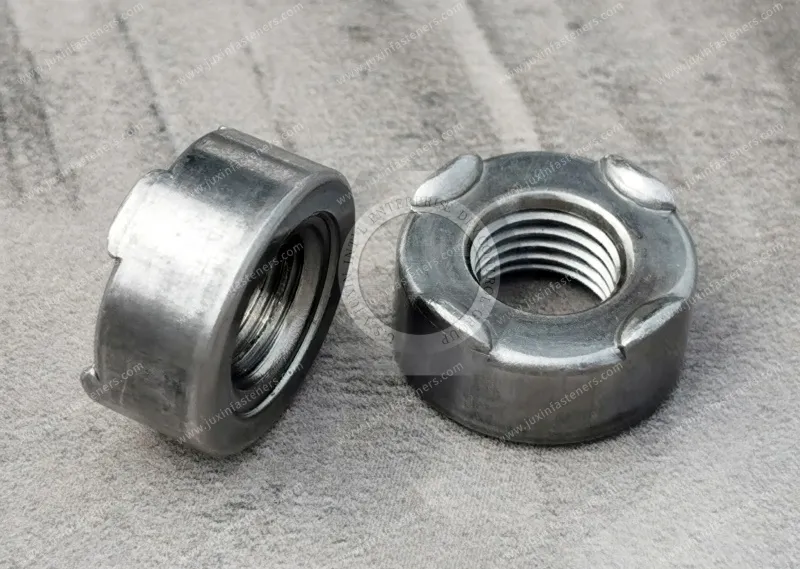
Resistance projection weld nuts provide threaded attachment points through a localized resistance welding process in which formed projections help concentrate current and heat at the joining interface.
They are widely considered for automotive sheet metal assemblies where the parent material, weld nut and manufacturing process are suitable for resistance welding.
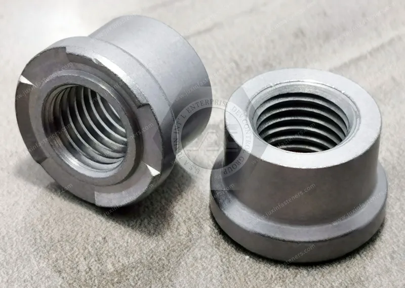
JUXIN FASTENERS supplies weld nut product families, including hexagonal weld nuts, square weld nuts and drawing-based projection weld nut configurations.
This engineering guide focuses on automotive seat frame and chassis bracket applications, with particular attention to:
Projection geometry
Welding consistency
Weld nut positioning
Thread protection
Galvanized sheet compatibility
Automotive steel selection
Weld strength validation
Automated feeding
Supplier qualification
OEM and Tier 1 purchasing requirements
A resistance projection weld nut is a threaded fastener designed to be attached to a compatible metallic workpiece through resistance welding.
The nut incorporates formed projections or other weld features that establish localized electrical and mechanical contact with the parent sheet.
During welding, electrical current and electrode force generate heat at the intended joining interface.
The resulting joint depends on the interaction of:
Weld nut geometry
Nut material
Parent sheet material
Surface condition
Electrode force
Welding current
Weld time
Electrode geometry
Equipment condition
A correctly specified weld nut is therefore only one part of a successful welding process.
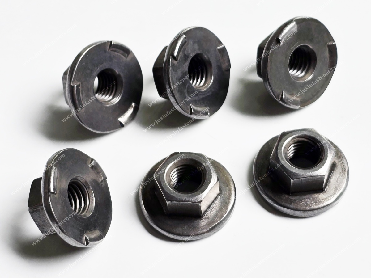
Relevant procurement and engineering terminology includes:
Projection weld nut
Resistance projection weld nut
Automotive weld nut
Hex weld nut
Square weld nut
DIN 929 weld nut
DIN 928 weld nut
Flange weld nut
Piloted weld nut
Weld nut for stamped steel
Weld nut for automotive seat frame
Weld nut for chassis bracket
These names describe related but not necessarily interchangeable configurations.
The drawing must establish the actual dimensions and weld features.
Automotive seat structures may contain stamped steel brackets and welded subassemblies requiring threaded attachment points.
Potential applications include:
Seat frame brackets
Adjustment mechanism mounting interfaces
Accessory mounting brackets
Seat structure subassemblies
Noncritical equipment attachment points
Drawing-specific structural connections
The suitability of a weld nut depends on the actual load path and safety requirements.
A component used in a seat structure is not automatically suitable for a safety-critical seat anchorage or restraint-related connection.
Those applications require specific engineering approval and validation.
Potential applications include:
Stamped chassis brackets
Body-in-white mounting points
Reinforcement brackets
Equipment mounting interfaces
Underbody sheet metal assemblies
Welded steel subassemblies
The exact weld nut should be selected according to the parent material, joining process and required joint performance.
This distinction is essential for automotive sourcing.
Weld Nut Quality
Includes:
Dimensions
Thread accuracy
Projection geometry
Material
Surface condition
Hardness where specified
Weld Joint Quality
Includes:
Weld formation
Mechanical strength
Failure mode
Process consistency
Parent sheet compatibility
Production equipment condition
A weld nut can pass incoming dimensional inspection but still produce an unacceptable weld if the welding process is not properly established.
Therefore, the fastener and the installed joint must be qualified separately.
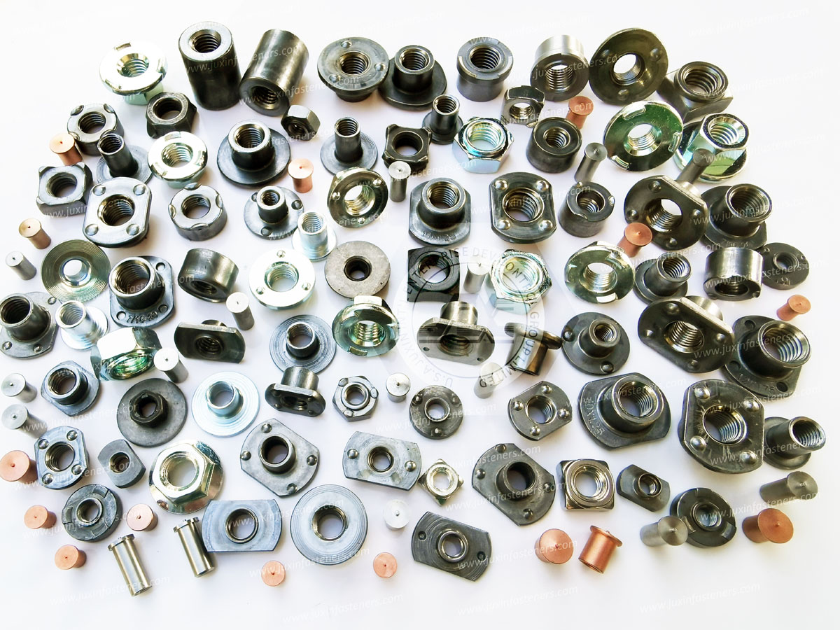
DIN 929 is a recognized dimensional reference for certain hexagonal weld nut configurations.
These nuts may be selected for suitable automotive and industrial sheet metal applications.
Potential considerations include:
Thread size
Nut height
Hexagonal dimensions
Weld projection geometry
Installation orientation
Parent sheet compatibility
The actual product should be checked against the applicable drawing and standard edition.
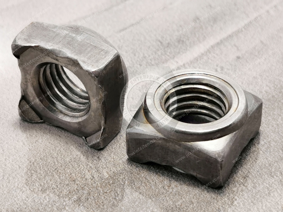
DIN 928 is a recognized dimensional reference for certain square weld nut configurations.
Square weld nuts may be considered for:
Stamped steel brackets
Automotive sheet metal
Equipment frames
Industrial welded assemblies
The correct selection depends on:
Available space
Weld nut geometry
Welding equipment
Feeding requirements
Joint performance
A square nut should not automatically be assumed to provide greater weld strength than a hexagonal nut.
A square weld nut may have a different footprint from a hexagonal weld nut.
However, weld strength depends on more than the external shape.
Important factors include:
Projection dimensions
Projection placement
Material
Parent sheet
Welding schedule
Electrode condition
Therefore, comparisons should be based on the actual welded assembly rather than the number of corners on the nut.
Flange weld nuts may incorporate an extended bearing or welding interface depending on the design.
Potential applications include:
Automotive mounting brackets
Structural sheet metal components
Equipment support assemblies
The actual flange geometry, projections and installation requirements must be confirmed from the drawing.
A flange does not automatically guarantee better weld performance or load distribution.
Some weld nuts include a pilot feature intended to assist positioning relative to a hole in the parent sheet.
Potential functions include:
Locating the nut
Supporting assembly positioning
Helping maintain alignment
However, a pilot does not automatically prevent weld spatter from entering the thread.
Thread protection depends on the complete design and welding process.
Projection geometry is a critical factor in resistance projection welding.
Important parameters may include:
Projection height
Projection width
Projection location
Number of projections
Forming consistency
Contact condition
Variations can influence how current and force are distributed during welding.
Three-projection and four-projection designs may be used in different applications.
However, increasing the number of projections does not guarantee improved strength.
If the projections do not collapse or heat consistently, the resulting weld may be uneven.
The correct configuration depends on:
Nut design
Parent sheet
Welding equipment
Electrode force
Welding schedule
The projection arrangement should be qualified through the actual welding process.
During resistance projection welding, the projections are intended to concentrate heat and deform under electrode force.
Uneven collapse may contribute to:
Inconsistent weld formation
Localized overheating
Incomplete joining
Excessive expulsion
Nut tilting
Potential causes include:
Projection height variation
Electrode misalignment
Uneven contact
Incorrect welding parameters
Surface contamination
A weld nut may have an accurately formed internal thread.
But if one projection contacts the sheet before the others, the initial current path may be uneven.
This can affect heat generation and projection collapse.
Therefore, incoming inspection for critical applications may need to include projection geometry—not only thread and overall dimensions.
Resistance welding performance depends on the interaction of current, force and time.
Insufficient heat generation may lead to inadequate joining.
Excessive heat generation may contribute to expulsion or damage.
Electrode force also influences contact resistance and projection collapse.
The correct welding schedule must be established for the actual nut and parent sheet combination.
The final weld is produced at the customer's manufacturing operation.
Its performance depends on:
Welding equipment
Electrode condition
Current
Force
Time
Sheet material
Coating
Fixture alignment
Therefore, fastener selection and welding process validation must be coordinated.
A dimensional certificate for the nut is not a substitute for weld qualification.
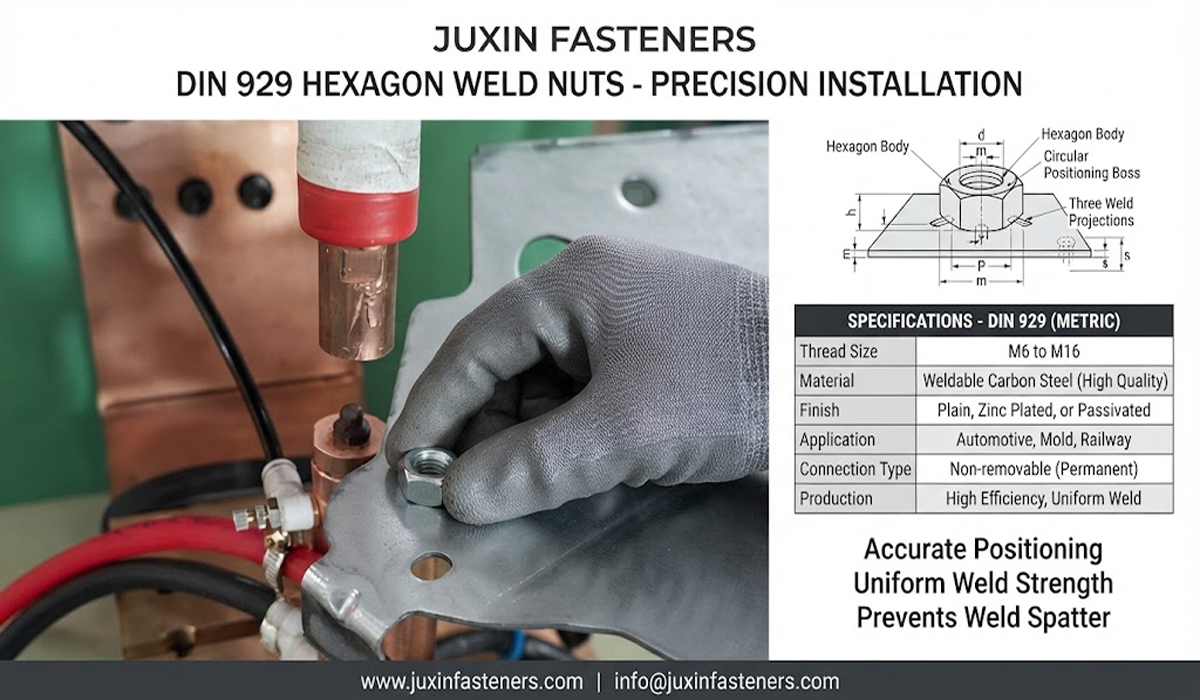
Weld expulsion occurs when molten material is expelled from the joining region.
Potential contributing factors include:
Excessive current
Inadequate electrode force
Poor contact
Surface contamination
Incorrect projection geometry
Equipment instability
Expulsion may create:
Contamination
Surface defects
Thread interference
Additional cleaning requirements
The correct solution depends on identifying the actual cause.
If spatter occurs during production, changing the weld nut may not be the correct first action.
The manufacturing team should also review:
Electrode wear
Welding current
Electrode force
Welding time
Nut positioning
Sheet coating
Surface cleanliness
A systematic process review is more reliable than assuming the nut is defective.
Automotive assembly operations require reliable bolt engagement.
Weld spatter or deformation affecting the internal thread may cause:
Difficult bolt installation
Cross-threading
Increased assembly torque
Rework
Scrap
The actual weld nut design and welding process should minimize the risk of thread interference.
A nut may pass thread inspection before welding.
However, the welding operation may introduce contamination or deformation.
For demanding applications, the OEM may require post-weld functional thread verification.
This helps distinguish incoming fastener quality from welding process effects.
Automated assembly requires accurate positioning of the nut relative to the parent sheet.
Potential concerns include:
Hole alignment
Nut orientation
Fixture accuracy
Pilot engagement
Electrode alignment
Part movement during welding
Misalignment can affect bolt assembly and the finished structure.
A nut may be dimensionally correct but incorrectly positioned by the feeding or fixturing system.
Therefore, dimensional inspection of the loose nut does not establish the final threaded-hole location.
The OEM should separately control:
Incoming nut geometry
Feeding orientation
Welding fixture position
Post-weld thread location
Automotive manufacturers frequently use zinc-coated sheet steel.
Resistance welding of coated sheet can be affected by the coating.
Potential considerations include:
Contact resistance
Heat generation
Electrode wear
Expulsion
Weld formation
Corrosion protection after welding
The welding process should be developed for the actual coating and sheet specification.
A weld nut may be suitable for welding to one coated steel grade but require a different welding schedule for another.
The OEM should identify:
Steel grade
Sheet thickness
Coating type
Coating mass or thickness
Welding equipment
Required weld performance
The nut and parent sheet must be evaluated as a combination.
Automotive structures may use:
Low-carbon steel
High-strength low-alloy steel
Advanced high-strength steel
Other specified automotive sheet grades
These materials can have different welding characteristics.
A weld nut suitable for low-carbon steel should not automatically be assumed suitable for every high-strength steel grade.
The parent sheet may have higher mechanical strength.
However, the weld interface and heat-affected region must still be suitable.
Potential issues include:
Localized hardening
Cracking
Inadequate weld formation
Sheet failure
Changes in failure mode
The actual joint should be validated.
Weld nut material should be selected according to:
Weldability
Mechanical properties
Formability
Thread requirements
Parent sheet compatibility
Surface condition
Low-carbon steels are commonly considered for suitable resistance welding applications.
However, the exact material grade must follow the applicable product specification.
Material selection affects electrical and thermal behavior during welding.
Projection geometry influences local contact and heat concentration.
Therefore, the two factors should not be evaluated independently when developing a welding process.
Surface condition can influence resistance welding.
Potential considerations include:
Oil
Oxide
Coating
Contamination
Storage condition
The appropriate condition should be specified according to the welding process.
An uncoated nut is not automatically contamination-free.
Likewise, a coated nut is not automatically unsuitable for resistance welding.
The actual finish and process must be evaluated.
Automotive welded assemblies may require corrosion protection.
Potential strategies depend on:
Nut material
Parent sheet
Coating
Welding process
Post-weld finishing
Service environment
A finish selected before welding may be affected by the welding operation.
The complete corrosion-protection strategy should be established by the OEM.
A protective coating on a loose weld nut may not provide the same protection after welding.
The welding process may locally alter the coating.
Therefore, the OEM should define whether corrosion requirements apply to:
The loose nut
The welded subassembly
The finished coated component
This distinction is important for supplier qualification.
Depending on the application, validation may include:
Push-out testing
Torque testing
Destructive weld evaluation
Metallographic examination
Thread verification
Dimensional inspection
Assembly-level mechanical testing
The required methods and acceptance criteria should be defined by the OEM.
Push-out testing evaluates resistance to displacement of the welded nut under a defined loading condition.
The result depends on:
Weld geometry
Parent sheet
Weld nut design
Welding process
Test fixture
Torque testing may be used to evaluate resistance to rotation or failure under a defined test arrangement.
The test procedure must identify:
Loading method
Fixture
Direction
Acceptance criterion
Failure mode
For weld nut qualification, the failure mode may provide important information.
For example, failure may occur through:
Weld separation
Parent sheet tearing
Nut deformation
Thread failure
Two assemblies with similar maximum loads may fail in different ways.
The OEM should consider both strength and failure mode where relevant.
Metallographic examination may be used to evaluate selected weld characteristics.
The method and acceptance criteria should follow the applicable welding specification.
A visually acceptable external weld does not automatically establish the required internal weld condition.
A weld nut may appear correctly positioned and welded.
However, appearance alone may not reveal all joining defects.
For critical applications, the inspection plan should be based on the actual risk and specification.
High-volume automotive production may use automated nut feeding and positioning systems.
Important variables include:
Nut geometry
Orientation features
Dimensional consistency
Surface condition
Feeding equipment
Transfer method
Welding fixture
The nut should be evaluated for compatibility with the customer's actual automation equipment.
Two weld nuts may have matching thread sizes and similar external dimensions.
However, small differences in geometry may affect:
Bowl feeding
Orientation
Transfer
Positioning
Jamming
Therefore, alternate supplier qualification should include the feeding process where automation is used.
| Selection Factor | DIN 929 Hex Weld Nut | DIN 928 Square Weld Nut |
|---|---|---|
| General geometry | Hexagonal | Square |
| Threaded function | Internal thread | Internal thread |
| Welding method | Resistance projection welding for suitable configurations | Resistance projection welding for suitable configurations |
| Space requirement | Geometry-dependent | Geometry-dependent |
| Feeding compatibility | Equipment-dependent | Equipment-dependent |
| Weld strength | Process-dependent | Process-dependent |
| Selection basis | Drawing and assembly requirements | Drawing and assembly requirements |
The correct choice should be established through engineering evaluation.
| Selection Factor | Projection Weld Nut | Self-Clinching Nut |
|---|---|---|
| Installation | Resistance welding | Mechanical pressing |
| Parent material | Weldable metallic substrate | Compatible deformable sheet |
| Heat input | Localized welding heat | No intentional welding heat |
| Retention | Metallurgical weld joint | Mechanical interlock |
| Main validation | Weld quality and mechanical strength | Push-out and torque-out |
| Manufacturing consideration | Welding equipment and process | Press tooling and sheet compatibility |
Neither solution is universally superior.
Blind rivet nuts are often considered where one-sided installation is required.
Projection weld nuts are generally selected where the manufacturing process provides suitable welding access and equipment.
The correct choice depends on:
Assembly sequence
Parent material
Installation access
Required performance
Production volume
A stamped steel component may be suitable for projection welding during early fabrication.
However, a completed enclosure or assembly may not allow practical access for resistance welding equipment.
Therefore, fastener selection should be coordinated with the manufacturing sequence.
Some automotive seat and chassis connections are safety-related.
Potential examples include selected:
Seat anchorage systems
Restraint-related structures
Crash-load-bearing connections
Structural attachment points
These applications may require additional qualification.
A weld nut should not be described as approved for safety-critical use without the relevant engineering evidence and customer authorization.
A supplier may manufacture a weld nut used in an automotive-type assembly.
That does not automatically establish approval for a specific OEM or Tier 1 program.
Qualification may depend on:
Customer drawing
Material specification
Process requirements
Validation tests
Quality documentation
Production approval
The applicable requirements must be agreed for the actual project.
For new or alternative weld nut sourcing, a practical qualification sequence may include:
Drawing Review → Material Review → Projection Geometry Review → Sample → Welding Trial → Mechanical Testing → Thread Verification
→ Automated Feeding Trial → Golden Sample Approval → Production
The exact sequence depends on the customer requirements.
Even if an alternative nut meets the same nominal drawing, changes in:
Projection geometry
Material
Surface condition
Hardness
Manufacturing variation
may affect welding behavior.
Therefore, the OEM should determine whether a supplier change requires welding trials or process revalidation.
Identify the seat frame, chassis bracket or sheet metal assembly.
Specify steel grade, thickness and coating.
Evaluate hex, square, flange or drawing-specific designs.
Specify size, pitch and tolerance.
Use the applicable drawing or product specification.
Confirm equipment and electrode compatibility.
Evaluate pilot, hole and fixture requirements.
Specify push-out, torque and other relevant tests.
Confirm feeding and orientation requirements.
Complete the required welding and mechanical qualification.
For accurate technical review and quotation, provide:
Product drawing or standard reference
Thread size and tolerance
Nut geometry
Projection configuration
Nut material
Parent sheet material
Sheet thickness
Coating specification
Surface condition
Welding process requirements
Push-out or torque requirements
Automated feeding requirements
Prototype quantity
Annual purchasing forecast
Packaging requirements
Required documentation
For custom weld nuts, provide a 2D drawing and available 3D model.
For high-volume automotive manufacturing, the total cost may be influenced by:
Feeding reliability
Welding consistency
Scrap
Rework
Thread cleaning
Inspection
Production downtime
Therefore, procurement should evaluate total assembly performance rather than unit price alone.
Depending on the project, inspection may include:
Dimensional verification
Thread inspection
Projection geometry measurement
Material verification
Surface condition inspection
Hardness where specified
Welding trial evaluation
Mechanical testing
Additional documentation should be agreed during RFQ review.
Depending on the actual product and application, relevant references may include:
DIN 929 for applicable hexagonal weld nut configurations
DIN 928 for applicable square weld nut configurations
ISO metric thread specifications
ASME/ANSI inch-thread specifications where applicable
ISO 14327 for resistance welding weldability procedures where relevant
ISO 18278 series for resistance spot welding weldability evaluation where applicable to the specified process and materials
Applicable ISO or ASTM material specifications
ASTM B117 for specified corrosion testing
EN 10204 for agreed inspection documentation
Customer-specific automotive drawings and welding specifications
The actual weld nut and resistance welding process must be evaluated according to the applicable requirements.
No single standard should be assumed to establish suitability for every automotive application.
Standard weld nuts cover many industrial applications.
Custom requirements may include:
Nonstandard threads
Special nut geometry
Modified projection configuration
Restricted installation space
Customer-specific material
Special positioning features
Drawing-specific mechanical requirements
JUXIN FASTENERS can review drawing-based projection weld nut requirements according to manufacturing feasibility.
A broader guide to projection weld nut selection for automotive sheet metal applications.
Mechanical press-in fastening alternatives for compatible sheet metal.
Rotational locking solutions for vibration-sensitive threaded joints.
Manufacturing process selection for drawing-based fasteners.
Threaded fastening where access is limited to one side.
These related solutions help engineers compare welding, clinching, blind-side installation and vibration locking requirements.
Are you sourcing projection weld nuts for:
Automotive seat frames
Body-in-white assemblies
Chassis brackets
Stamped steel components
Industrial welded structures
Commercial vehicle equipment
Automated sheet metal manufacturing
JUXIN FASTENERS can review standard and drawing-based weld nut requirements for industrial OEM applications.
For efficient technical evaluation, send:
Drawing + Thread Size + Nut Geometry + Projection Configuration + Parent Sheet Material + Surface Condition + Quantity
If your project includes automotive safety-critical requirements, welding qualification or automated feeding, please include the relevant specifications.
The objective is to select a weld nut that satisfies the actual welding process and assembly requirements—not merely one that matches the nominal thread size.
JUXIN FASTENERS
Website: www.juxinfasteners.com
Engineering & RFQ: info@juxinfasteners.com
Send your drawing and application requirements for technical review and quotation.
Product Packaging
Packaging Standard
At Juxin Fasteners, we apply standardized export packaging to ensure product protection, traceability, and compliance with international logistics requirements.
1. Standard Export Packaging
Unless otherwise specified, all products will be packed according to our factory standard export packaging, which includes:
Moisture-resistant inner protection
Poly bag or small box packing as required
Reinforced export cartons
Clear labeling with part number, specification, batch number, and quantity
Palletizing for sea or air shipment when necessary
Our standard packaging is designed to ensure safe transportation, efficient warehousing, and long-distance international shipping.
2. Customized Packaging Options
We also provide customized packaging solutions according to customer requirements, including but not limited to:
Private labeling
Customized barcodes
Specific carton dimensions
Retail packaging
Special pallet configuration
Customer-specific marking and identification
So that you know, customized packaging may involve additional costs and extended lead time depending on the complexity of the requirements.
3. Compliance & Quality Assurance
All packaging processes are controlled under our ISO 9001 quality management system to ensure consistency, traceability, and product integrity throughout the supply chain.
Product Pictures
Contact Us
Tel.:
+86 020 8621 0320
+86 020 3121 6067
E-mail:
Technical Support:
Navigation
SEND INQUIREY