Call Us
+86 136 6007 9809
Call Us
+86 136 6007 9809

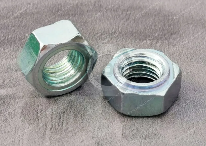
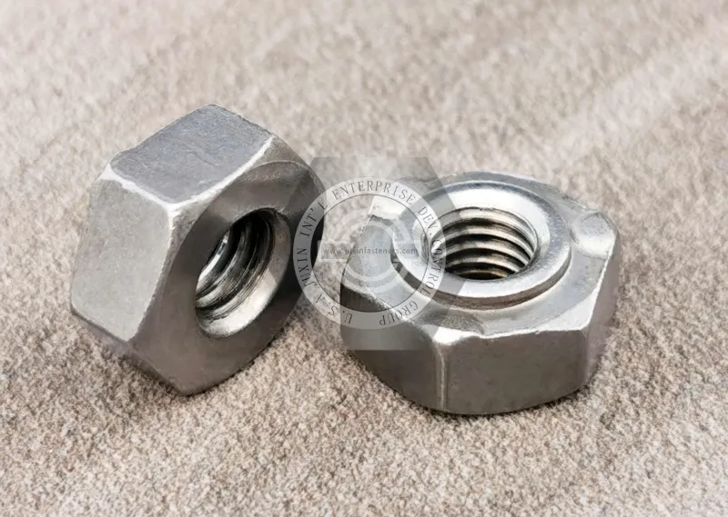
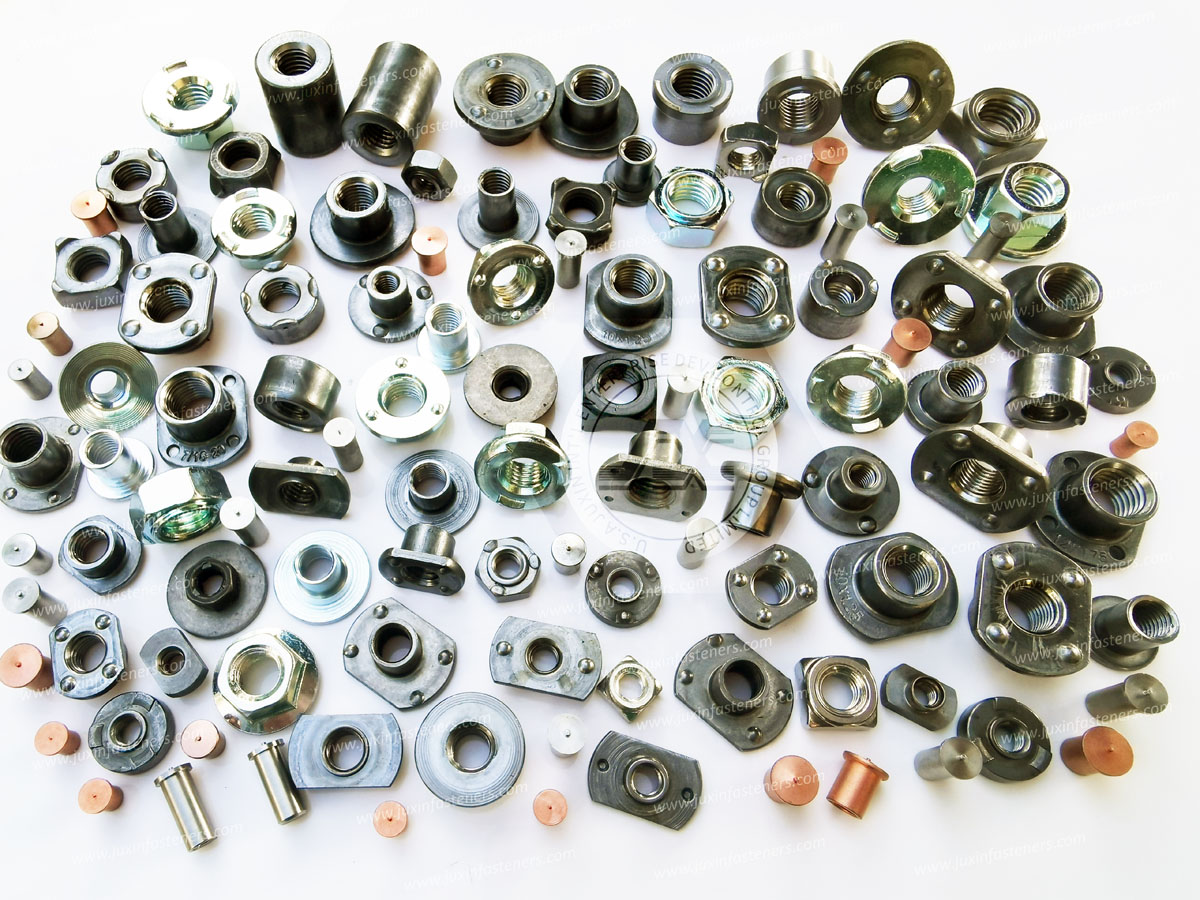
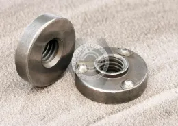
DIN 929 hex weld nuts are internally threaded steel fastening components designed for attachment to suitable metal substrates through resistance projection welding.
Their hexagonal body and welding projections provide a practical method of creating permanent threaded attachment points in sheet metal and fabricated steel assemblies.
Product Specification
DIN 929 hex weld nuts are internally threaded steel fastening components designed for attachment to suitable metal substrates through resistance projection welding.
Their hexagonal body and welding projections provide a practical method of creating permanent threaded attachment points in sheet metal and fabricated steel assemblies.
These industrial weld nuts are widely considered for automotive components, industrial machinery, electrical enclosures, commercial equipment, sheet metal fabrications,
and other OEM applications requiring repeatable threaded connections.
Unlike loose nuts that require access to both sides of an assembly, a properly welded nut becomes a fixed threaded component of the fabricated structure.
This can simplify subsequent bolt installation, reduce loose-part handling, and support efficient production-line assembly.
However, reliable performance depends on more than the dimensional accuracy of the weld nut.
Engineers must consider the parent sheet material, nut projection geometry, hole alignment, welding equipment, electrode force, welding current,
surface condition, and the mechanical requirements of the completed joint.
JUXIN FASTENERS supplies industrial fastening components, including weld nuts and drawing-based OEM fastening solutions, for international manufacturing and procurement applications.
This engineering guide examines DIN 929 hex weld nut specifications, material compatibility, resistance projection welding,
manufacturing process control, common welding defects, inspection requirements, industrial applications, and commercial sourcing considerations.
A DIN 929 hex weld nut is a hexagonal internally threaded nut with welding projections designed to concentrate electrical current and contact pressure during resistance projection welding.
When the nut is positioned against a compatible metal substrate, the projections establish localized contact points between the nut and the sheet.
During the welding process, electrical resistance generates heat at the contact interfaces while electrode force promotes the formation of welded connections.
After welding, the nut provides a fixed internal thread for subsequent bolt assembly.
DIN 929 specifies a particular family of hexagon weld nuts with defined dimensional characteristics.
Important features include:
Hexagonal external body.
Internal metric thread.
Defined nut height and across-flats dimensions.
Welding projections on the designated welding face.
Dimensional relationships established by the applicable standard.
Geometry intended for resistance projection welding.
The welding projections are important functional features rather than merely cosmetic details.
Their shape, location, and dimensional consistency influence current concentration, initial contact conditions, and weld formation.
For OEM applications, engineers should use the applicable DIN 929 dimensional requirements and approved product drawings rather than relying only on nominal thread size.
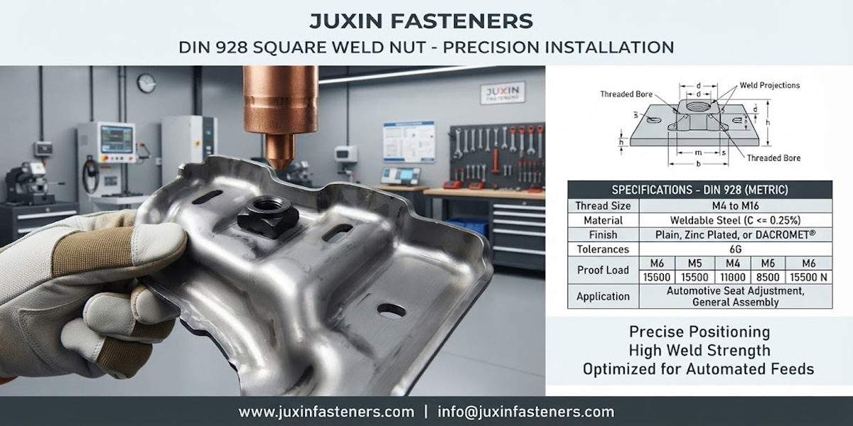
DIN 929 and DIN 928 are different weld nut standards.
DIN 929 describes hexagon weld nuts, while DIN 928 describes square weld nuts.
The differences include external body geometry and applicable dimensional requirements.
These products should not be treated as direct substitutes solely because they share the same internal metric thread.
Before considering an alternative, engineers should verify:
Nut body dimensions.
Projection configuration.
Available welding space.
Electrode and tooling compatibility.
Hole alignment requirements.
Welding process qualification.
Required joint strength.
Existing production equipment.
A change from a DIN 929 hex weld nut to a DIN 928 square weld nut may require tooling changes and renewed welding validation.
DIN 929 weld nuts are selected using the applicable standard dimensions and the engineering requirements of the completed assembly.
The nominal thread designation alone does not fully define the part.
An OEM drawing or purchasing specification should identify the relevant dimensional requirements, including:
Nominal metric thread size.
Thread pitch.
Across-flats dimension.
Nut height.
Projection geometry.
Welding face orientation.
Relevant dimensional tolerances.
Material specification.
Surface condition.
The correct values should be taken from the applicable standard edition and the approved part drawing.
Metric thread designations commonly used in industrial fastening applications include M4, M5, M6, M8, and other sizes where supported by the relevant product standard.
The availability of a particular DIN 929 size must be confirmed against the actual product specification.
For example:
M4 × 0.7 — Nominal thread diameter 4 mm, pitch 0.7 mm.
M5 × 0.8 — Nominal thread diameter 5 mm, pitch 0.8 mm.
M6 × 1.0 — Nominal thread diameter 6 mm, pitch 1.0 mm.
M8 × 1.25 — Nominal thread diameter 8 mm, pitch 1.25 mm.
These are examples of metric coarse thread designations, not a complete DIN 929 dimensional table or a guarantee of stock availability.
An M6 nominal thread diameter corresponds to approximately 0.2362 inches.
This conversion is provided for dimensional reference only.
ISO metric threads, UNC, UNF, BSW, and BSF threads use different thread systems and must not be assumed to be interchangeable.
DIN 929 is a metric weld nut standard. A custom weld nut with a Unified or British thread should be specified separately rather than described as a standard DIN 929 product.
Where an OEM drawing requires UNC, UNF, BSW, or BSF threads, the thread form, pitch, tolerance requirements, and manufacturing feasibility must be confirmed independently.
Material compatibility is a critical factor in resistance projection welding.
A weld nut with correct dimensions may still produce an unreliable joint if its material, surface condition, or projection geometry is incompatible with the parent sheet and welding process.
Low-carbon steel is commonly considered for resistance-welded fasteners because suitable grades can provide useful formability and weldability.
However, weldability depends on the actual chemical composition, metallurgical condition, geometry, and welding process.
The designation "low-carbon steel" alone does not establish a guaranteed welding result.
OEM specifications should identify the required material grade or approved alternatives.
DIN 929 weld nuts may be evaluated for welding to compatible steel sheet materials used in automotive and industrial fabrication.
Examples of sheet material specifications that may be encountered include:
EN 10130 DC01 — Cold-rolled low-carbon steel flat products for cold forming.
EN 10130 DC04 — Cold-rolled low-carbon steel with deeper drawing characteristics.
ASTM A1008/A1008M — Steel sheet, cold-rolled, including applicable commercial and forming grades.
These are examples of relevant parent sheet material specifications. They do not automatically establish weld compatibility with every DIN 929 nut.
The actual grade, coating, sheet thickness, and welding requirements must be evaluated together.
Chemical composition can influence resistance welding behavior, particularly when higher-strength or alloyed steels are involved.
Carbon content, alloying elements, hardenability, and the thermal cycle may affect the resulting weld and heat-affected zone.
For critical applications, material compatibility should be assessed using the actual material specifications and suitable welding qualification procedures.
A universal carbon-equivalent limit should not be assumed without an applicable engineering basis.
Some OEM applications may require stainless steel welded threaded components.
However, a stainless steel weld nut should not automatically be described as equivalent to a standard carbon steel DIN 929 weld nut.
Differences in electrical resistance, thermal behavior, material properties, and weldability can affect the welding process.
Material substitutions must be reviewed against the drawing and validated for the intended assembly.
The suitability of a DIN 929 weld nut depends on the relationship between the nut, parent sheet, receiving hole, and applied loads.
There is no single universal sheet thickness range that guarantees acceptable welding performance for every nut size and material combination.
Sheet thickness influences heat distribution, mechanical stiffness, electrode indentation, and the risk of burn-through.
Thin sheets may require particular attention to:
Localized overheating.
Sheet deformation.
Excessive indentation.
Projection collapse behavior.
Weld penetration.
Thread alignment.
Mechanical load capacity.
Thicker sheets may require different welding conditions because of their thermal and electrical characteristics.
The acceptable thickness range should be established for the selected nut, material combination, equipment, and validated welding procedure.
The parent sheet hole must accommodate the mating screw while allowing accurate positioning of the weld nut.
The hole size and position should be defined by the assembly drawing.
An incorrectly sized or misaligned hole can interfere with bolt installation or cause the welded nut to be positioned incorrectly.
Concentricity between the weld nut thread and parent sheet hole is important for subsequent bolt assembly.
Poor alignment may cause:
Cross-threading.
Difficulty with automated screw installation.
Increased assembly torque.
Bolt interference.
Rework or rejected assemblies.
Locating pins and suitable fixtures can help control alignment during welding.
Engineers should also consider the distance between the weld nut and nearby sheet edges, bends, formed features, or other welded components.
Insufficient surrounding material or unsuitable joint geometry may reduce assembly stiffness or create local stress concentrations.
The required edge distance and surrounding sheet geometry should be determined from the actual component design and loading conditions.
Resistance projection welding joins components by passing electrical current through localized contact areas while applying mechanical force.
For DIN 929 hex weld nuts, the projections are intended to concentrate the initial contact conditions at designated locations.
As the welding cycle progresses, localized heating and deformation of the projections contribute to the formation of the welded joint.
The process must be controlled to achieve consistent weld quality without excessive sheet deformation, thread damage, or spatter.
Welding current is a major process variable because it influences the rate of heat generation at the contact interfaces.
Insufficient current may produce incomplete bonding.
Excessive current may cause expulsion, excessive indentation, or damage to the parent sheet.
The required current depends on:
Nut size and projection geometry.
Nut material.
Parent sheet material.
Sheet thickness.
Surface coatings.
Electrode configuration.
Welding equipment.
Current waveform and welding time.
No single current setting is appropriate for all DIN 929 weld nuts.
Electrode force maintains contact between the components and influences projection deformation during welding.
Insufficient force can produce unstable contact conditions and excessive localized heating.
Excessive force may prematurely flatten the projections, alter current distribution, or deform the sheet.
The correct force must be established through process development and welding validation.
Welding time affects the thermal energy delivered to the joint.
The appropriate duration depends on current magnitude, material characteristics, projection geometry, and equipment.
Cycle counts must be interpreted according to the welding equipment and electrical frequency.
For example, a welding controller operating with a 50 Hz reference has a different cycle duration from one using a 60 Hz reference.
Modern inverter welding equipment may use different control methods and timing conventions.
Therefore, welding time should be specified according to the actual equipment and validated procedure rather than copied from an unrelated application.
Squeeze time allows the electrodes to establish the required mechanical contact before welding current is applied.
Hold time maintains force after current flow to support joint solidification and stabilization.
These settings must be coordinated with the selected welding process.
Projection collapse is an important characteristic of the welding cycle.
The projections must deform in a controlled manner while developing the required welded interfaces.
Uneven collapse may indicate problems with:
Projection dimensional consistency.
Electrode alignment.
Nut positioning.
Surface condition.
Electrode force.
Welding current distribution.
Projection collapse alone does not prove that the completed weld meets the required mechanical strength.
Production engineers should treat welding parameters as validated process settings rather than universal product specifications.
The correct process window must be established for the actual nut, sheet material, coating, equipment, and quality requirements.
| Process Variable | Engineering Function | Potential Problem if Incorrect |
|---|---|---|
| Welding current | Controls electrical heat generation | Incomplete bonding or excessive expulsion |
| Electrode force | Maintains contact and influences projection collapse | Unstable weld formation or excessive deformation |
| Welding time | Controls duration of energy input | Insufficient fusion or overheating |
| Squeeze time | Establishes contact before current application | Inconsistent initial contact |
| Hold time | Maintains force after welding | Inconsistent joint stabilization |
| Electrode alignment | Controls pressure and current distribution | Uneven projection collapse |
| Surface condition | Influences electrical contact resistance | Variable weld quality |
| Nut positioning | Controls thread-to-hole alignment | Assembly interference and rejected parts |
A practical engineering approach includes:
Confirm the nut drawing, material, and projection geometry.
Verify parent sheet grade, thickness, and coating.
Select suitable welding equipment and electrodes.
Establish initial settings using applicable equipment guidance and engineering experience.
Conduct controlled welding trials.
Evaluate weld quality using agreed inspection and testing methods.
Identify a stable process window.
Document approved settings and acceptance criteria.
Monitor production consistency.
For automotive or other demanding OEM applications, additional process qualification may be required by the customer.
Applicable standards should be selected according to the welding process and customer requirements.
ISO 14373 provides a procedure for resistance spot welding of uncoated and coated low-carbon steels, and may offer relevant background for resistance welding process control.
It is not a substitute for a projection-welding-specific procedure.
ISO 15609-5 addresses welding procedure specification content for resistance welding.
ISO 15614-12 addresses welding procedure qualification for resistance spot, seam, and projection welding.
The applicability of each standard, including its edition and scope, should be confirmed for the actual manufacturing project.
Customer-specific welding specifications may impose additional requirements.
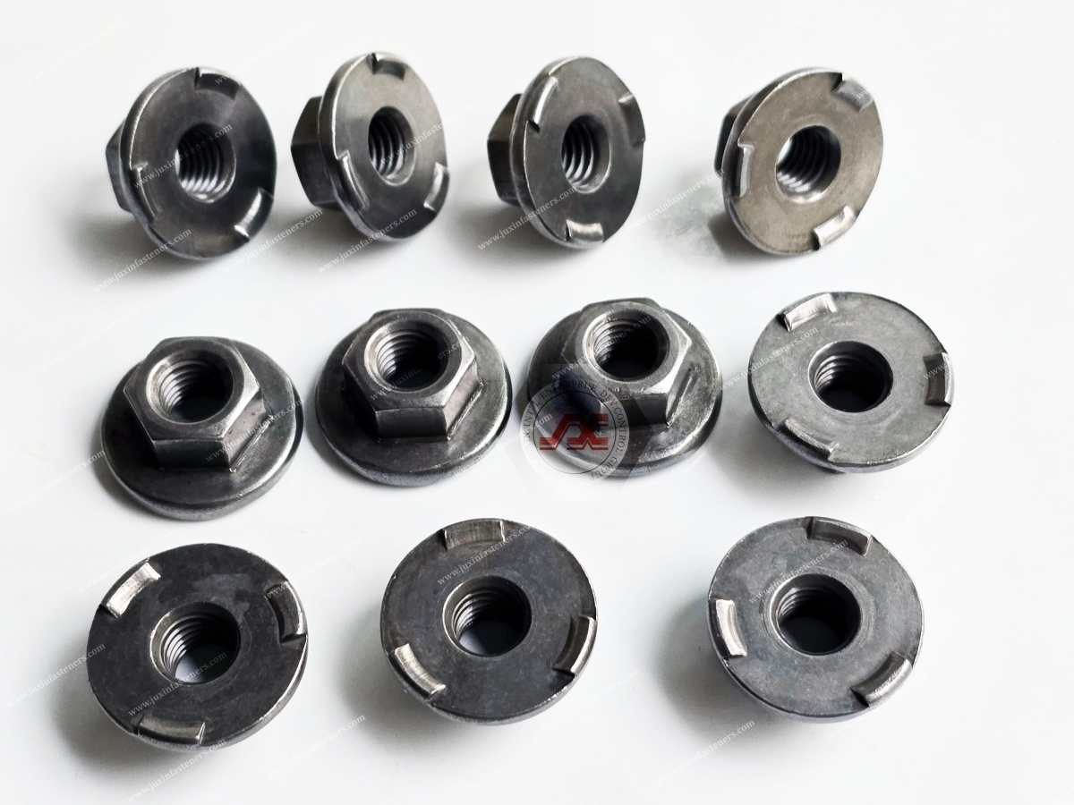
DIN 929 weld nuts can be incorporated into manual, semi-automated, and automated resistance welding operations.
For high-volume OEM manufacturing, the objective is not simply to achieve an acceptable weld during initial trials.
The production process must consistently produce correctly positioned nuts with acceptable weld integrity and thread functionality.
Automated welding systems may use vibratory feeders, mechanical transfer systems, or other suitable feeding equipment.
Reliable feeding depends on the consistency of the nut geometry and the compatibility of the feeding mechanism.
Important considerations include:
Across-flats dimensions.
Nut height.
Orientation.
Projection geometry.
Surface condition.
Part-to-part dimensional variation.
Feeding track design.
Tooling clearances.
Dimensional variation can increase feeding interruptions or misorientation.
Fixtures help maintain the relationship between the weld nut and the parent sheet.
Locating pins may be used to align the nut with the sheet hole.
However, the pin geometry must be designed to locate the nut without damaging the internal thread or creating unnecessary interference.
The correct locating arrangement depends on the nut geometry, thread size, and welding tooling.
Electrode wear can change contact conditions and affect weld consistency.
Production teams should establish maintenance and inspection procedures appropriate to the equipment and welding process.
Potential maintenance considerations include:
Electrode surface condition.
Alignment.
Cooling performance.
Contact geometry.
Wear and contamination.
Replacement intervals based on validated production experience.
Welding cycle time is influenced by more than the duration of electrical current flow.
Total cycle time may include:
Nut feeding.
Component positioning.
Fixture clamping.
Electrode movement.
Welding.
Hold time.
Part release.
Inspection or transfer.
Production managers should evaluate the complete assembly cycle rather than comparing only welding current duration.
The total cost of a welded threaded connection includes the nut, welding operation, equipment utilization, inspection, scrap, rework, and subsequent bolt assembly.
A lower-cost nut may create higher total manufacturing costs if inconsistent geometry causes frequent feeding problems or welding defects.
For repeat OEM programs, consistent part dimensions and stable welding behavior can be important purchasing considerations.
Understanding common defects helps manufacturing engineers identify process risks and establish corrective actions.
Possible causes include:
Insufficient welding energy.
Inappropriate electrode force.
Poor contact conditions.
Contaminated surfaces.
Incorrect projection geometry.
Equipment instability.
Corrective evaluation should include the welding settings, material specifications, projection dimensions, and actual weld condition.
A weak weld should not automatically be corrected by increasing current without examining the complete process.
Weld spatter or expulsion can occur when molten material is ejected from the welding interface.
Possible contributing factors include:
Excessive localized heating.
Unstable contact conditions.
Inappropriate electrode force.
Uneven projection collapse.
Surface contamination.
Excessive spatter may damage the component or interfere with subsequent assembly.
The welding process should be reviewed to identify the underlying cause.
Uneven projection collapse may result from:
Incorrect nut positioning.
Electrode misalignment.
Projection dimensional variation.
Uneven parent sheet contact.
Inconsistent electrode pressure.
This condition can produce nonuniform weld formation.
Potential causes include:
Excessive thermal exposure.
Weld spatter entering the internal thread.
Incorrect locating pin geometry.
Mechanical deformation.
Misalignment during welding.
Thread functionality should be evaluated according to the applicable inspection requirements.
Post-weld thread chasing should not be assumed to be an acceptable corrective operation unless specifically approved.
Burn-through can occur when excessive localized heating damages the parent sheet.
Risk depends on sheet thickness, material, welding energy, electrode conditions, and joint geometry.
Corrective actions should be based on controlled process evaluation.
A misaligned nut can create difficulties during subsequent bolt installation.
Potential causes include:
Incorrect fixture positioning.
Inadequate locating pin control.
Part movement during welding.
Inconsistent sheet hole location.
Feeding or transfer errors.
Alignment should be verified against the assembly drawing.
A completed DIN 929 welded assembly should be evaluated according to the mechanical requirements of its intended application.
Dimensional conformity of the nut does not automatically establish acceptable weld strength.
Visual inspection may identify:
Incorrect nut position.
Excessive spatter.
Visible sheet deformation.
Missing or incomplete weld features.
Surface damage.
Other visible welding defects.
However, visual inspection alone may not establish internal weld integrity or mechanical strength.
Relevant dimensional checks may include:
Nut position relative to the sheet hole.
Thread alignment.
Nut seating condition.
Sheet deformation.
Thread functionality.
Assembly fit.
Depending on the application, OEM requirements may include destructive or nondestructive evaluation methods appropriate to the welded joint.
Possible evaluation approaches include:
Push-off testing.
Torque-based weld integrity testing.
Peel or chisel-type evaluation where appropriate.
Metallographic examination.
Other customer-approved methods.
Test methods and acceptance criteria must be selected for the actual joint design.
A push-off test result and a torque-based test result evaluate different aspects of joint performance and should not be treated as interchangeable.
Internal thread functionality may be verified using appropriate thread gauges or agreed functional inspection methods.
Thread inspection should consider the effects of welding, handling, and subsequent surface processing.
For high-volume production, the inspection plan may include:
First-off inspection.
Periodic dimensional checks.
Welding parameter monitoring.
Weld integrity sampling.
Thread gauge inspection.
Process change verification.
Nonconforming product control.
Sampling frequency and acceptance criteria should be established according to the customer specification and applicable quality plan.
OEM buyers may request material identification, dimensional reports, inspection records, or other supporting documentation.
Requirements such as EN 10204 inspection documents, production part approval submissions, or customer-specific quality records should be reviewed individually.
The availability of particular documentation must be confirmed before quotation or order acceptance.
Surface condition can significantly influence resistance projection welding.
A coating that provides corrosion protection may also affect electrical contact resistance and weld formation.
Uncoated or appropriately prepared steel weld nuts may be selected where the welding process requires direct metal contact.
Corrosion protection can then be addressed according to the completed assembly's requirements.
Zinc coatings can affect resistance welding behavior because of their electrical, thermal, and metallurgical characteristics.
Welding conditions may need to be adjusted for coated materials.
Coating thickness, uniformity, and the specific welding process should be considered.
Some assemblies may receive corrosion protection after welding.
The selected treatment should be compatible with the completed assembly and any subsequent thread requirements.
Engineers should evaluate whether coating buildup affects bolt installation or thread functionality.
Stainless steel and dissimilar metal assemblies require additional consideration of weldability, electrical resistance, thermal behavior, and corrosion mechanisms.
A standard carbon steel welding procedure should not be transferred to a different material combination without validation.
Where corrosion testing is required, the test method, coating system, acceptance criteria, and exposure duration must be defined.
ASTM B117 describes salt spray testing practice, but a particular exposure duration does not directly establish real-world service life.
Corrosion resistance claims must be supported by applicable product or assembly testing.
DIN 929 hex weld nuts may be considered for automotive sheet metal components requiring fixed threaded attachment points.
Potential applications include suitable brackets, body-related sheet metal parts, mounting assemblies, and fabricated components.
Automotive engineers should evaluate:
Weld integrity.
Parent sheet material.
Vibration loading.
Corrosion protection.
Bolt assembly requirements.
Production repeatability.
Customer-specific qualification requirements.
Safety-critical applications require the appropriate engineering approval and validation.
Industrial machinery may require welded threaded attachment points for covers, mounting brackets, guards, and fabricated steel components.
Design considerations include mechanical loading, service access, installation space, and environmental conditions.
Weld nuts may be used in suitable steel enclosures, equipment brackets, and mounting structures.
Engineers should evaluate enclosure material, sheet thickness, grounding design, corrosion protection, and equipment-specific requirements.
A welded nut does not independently establish electrical grounding performance or regulatory compliance.
Heating, ventilation, air-conditioning, and commercial equipment manufacturers may use welded nuts in suitable sheet metal assemblies.
Production requirements may include efficient assembly, consistent bolt installation, vibration resistance of the completed joint, and corrosion protection.
Welded threaded components may be considered for fabricated steel parts used in agricultural machinery and construction equipment.
The joint design must account for actual mechanical loading, environmental exposure, and maintenance requirements.
Weld nuts can simplify the assembly of metal housings, panels, brackets, and equipment frames by providing fixed threaded locations.
For high-volume fabrication, dimensional consistency and welding process stability are important to efficient downstream assembly.
DIN 929 weld nuts are one of several options for creating threaded attachment points in metal assemblies.
The appropriate solution depends on material compatibility, access, production volume, equipment, and joint performance requirements.
| Fastener Type | Typical Installation Principle | Important Selection Considerations |
|---|---|---|
| DIN 929 hex weld nut | Resistance projection welding | Weldable substrate, welding access, tooling, weld qualification |
| DIN 928 square weld nut | Resistance projection welding | Different body geometry, tooling and dimensional requirements |
| Self-clinching nut | Press installation into suitable sheet metal | Sheet hardness, thickness, hole preparation, installation force |
| Blind rivet nut | Mechanical deformation from accessible side | Grip range, hole geometry, installation access, spin-out resistance |
| Loose hex nut | Mechanical bolt-and-nut assembly | Access to both sides, handling and assembly requirements |
| Custom weld nut | Application-specific welded geometry | Drawing requirements, manufacturing feasibility and weld validation |
DIN 929 may be suitable when:
The parent material is compatible with resistance projection welding.
A fixed threaded attachment point is required.
Welding equipment and access are available.
The joint geometry supports suitable positioning.
The welding process can be validated.
Production volumes justify the selected manufacturing process.
A self-clinching nut may be considered where the sheet material and geometry support mechanical installation.
A blind rivet nut may be considered where access is available from only one side and welding is not appropriate.
A custom weld nut may be considered when standard body geometry does not meet the available space or tooling requirements.
Alternative fasteners must be evaluated according to the actual engineering design rather than selected solely on unit price.
For purchasing managers and supplier development teams, a clear technical specification helps reduce quotation errors and supplier qualification delays.
A complete RFQ should define the actual part rather than simply requesting a DIN 929 weld nut.
Specify:
DIN 929 designation.
Applicable standard edition, if required.
Nominal metric thread size.
Thread pitch.
Dimensional requirements.
Drawing revision.
Any deviations from the standard.
Identify the required material grade or approved alternatives.
If a particular chemical composition or mechanical property requirement applies, it should be included in the purchasing specification.
Specify whether the nut is required in an uncoated condition, with a particular surface treatment, or with other agreed corrosion protection requirements.
The surface condition must be compatible with the intended welding process.
For technical evaluation, provide:
Parent sheet material.
Sheet thickness.
Surface coating.
Sheet hole diameter.
Weld nut position.
Available welding equipment.
Relevant assembly constraints.
The weld nut supplier and welding operation may have different responsibilities, which should be clarified during supplier qualification.
Identify any required:
Dimensional inspection.
Thread gauging.
Material documentation.
Packaging controls.
Lot identification.
Customer-specific approval documents.
Mechanical test requirements.
The supplier's ability to provide particular documents or testing must be confirmed.
Include:
Initial order quantity.
Estimated annual usage.
Sample requirements.
Delivery destination.
Target lead time.
Packaging requirements.
Forecast or scheduled delivery expectations.
For recurring OEM programs, consistent drawing revisions and clear purchasing forecasts can support more reliable supply planning.
International OEM purchasing decisions should consider more than the quoted price per weld nut.
A component that is dimensionally inconsistent or incompatible with the customer's welding equipment can create substantial downstream manufacturing costs.
Consistent nut geometry helps maintain predictable feeding, positioning, and welding conditions.
Critical dimensions should be defined in the approved drawing and inspection requirements.
Projection dimensions can influence initial contact conditions and welding behavior.
Variation between production batches may require welding process adjustments or increase quality risks.
For high-volume programs, projection geometry should be treated as an important functional characteristic.
The selected weld nut should be compatible with the customer's feeding, positioning, welding, and bolt assembly operations.
A part that meets nominal dimensional requirements may still require production trials to establish compatibility with existing equipment.
Packaging should protect the nuts from unacceptable damage, contamination, and handling-related deformation.
For automated feeding applications, packaging and surface condition can affect production efficiency.
Packaging requirements should be agreed during procurement.
Changes in material, geometry, manufacturing process, or surface condition may influence welding behavior.
For qualified OEM applications, changes should be reviewed according to the customer's approval requirements.
Supply chain managers should evaluate:
Specification consistency.
Production quantity requirements.
Agreed inspection controls.
Drawing revision management.
Delivery scheduling.
Commercial terms.
Supplier communication.
Change notification requirements.
The objective is to support repeatable manufacturing and predictable purchasing performance over the life of the OEM program.
DIN 929 covers hexagon weld nuts, while DIN 928 covers square weld nuts.
Their external geometry and dimensional requirements differ.
They should not be treated as interchangeable without engineering and welding process evaluation.
They may be suitable for certain thin sheet metal applications, depending on nut size, sheet material, thickness, joint geometry, and welding process.
No universal minimum sheet thickness should be assumed without validation.
The required welding current depends on the nut geometry, parent sheet, material combination, coating, welding equipment, electrode conditions, and welding time.
It must be established through appropriate process development and validation.
Suitable DIN 929 weld nuts can be incorporated into automated welding systems when feeding, positioning, tooling, and welding requirements are compatible.
Production trials should verify repeatability.
Possible causes include incomplete welding, insufficient joint strength, inappropriate test conditions, excessive applied torque, material defects, or process variation.
The failure mode should be investigated before changing the weld nut or welding settings.
Surface treatment requirements must be reviewed for compatibility with the intended welding process.
Zinc coatings may influence resistance welding behavior.
The required coating condition should be specified and validated.
No.
DIN 929 uses metric thread requirements. UNC and UNF belong to different thread systems.
Custom inch-thread weld nuts require separate specifications and manufacturing feasibility confirmation.
The standard designation, thread size, material, surface condition, quantity, and delivery requirements are essential starting points.
For application-specific review, the parent sheet material, thickness, welding requirements, and engineering drawing should also be provided.
JUXIN FASTENERS supports international B2B procurement inquiries for industrial weld nuts, sheet metal fastening components, and drawing-based OEM fastening requirements.
Whether your project involves automotive sheet metal assemblies, industrial machinery, electrical enclosures, HVAC equipment, or fabricated steel components, clearly defined technical specifications help establish an accurate quotation and appropriate product selection.
For DIN 929 hex weld nuts and related OEM welding fasteners, please provide the following information:
DIN 929 standard designation and required thread size.
Applicable 2D engineering drawing or 3D CAD model, where available.
Required material grade.
Surface treatment or coating requirements.
Parent sheet material and thickness.
Hole diameter and installation geometry.
Relevant welding and assembly requirements.
Inspection and quality documentation requirements.
Sample quantity and initial production order quantity.
Estimated annual purchasing volume.
Target delivery schedule and destination.
For custom weld nut requirements, please identify any deviations from standard dimensions, projection geometry, material specifications, or other critical characteristics.
Our team can review the submitted product specifications and confirm the applicable sourcing, manufacturing feasibility, and quotation requirements.
Company: JUXIN FASTENERS
Website: www.juxinfasteners.com
Email: info@juxinfasteners.com
Contact JUXIN FASTENERS with your engineering drawings, technical specifications, and purchasing requirements to request a quotation for DIN 929 hex weld nuts, projection weld nuts, and related industrial OEM fastening components.
Product Packaging
Packaging Standard
At Juxin Fasteners, we apply standardized export packaging to ensure product protection, traceability, and compliance with international logistics requirements.
1. Standard Export Packaging
Unless otherwise specified, all products will be packed according to our factory standard export packaging, which includes:
Moisture-resistant inner protection
Poly bag or small box packing as required
Reinforced export cartons
Clear labeling with part number, specification, batch number, and quantity
Palletizing for sea or air shipment when necessary
Our standard packaging is designed to ensure safe transportation, efficient warehousing, and long-distance international shipping.
2. Customized Packaging Options
We also provide customized packaging solutions according to customer requirements, including but not limited to:
Private labeling
Customized barcodes
Specific carton dimensions
Retail packaging
Special pallet configuration
Customer-specific marking and identification
So that you know, customized packaging may involve additional costs and extended lead time depending on the complexity of the requirements.
3. Compliance & Quality Assurance
All packaging processes are controlled under our ISO 9001 quality management system to ensure consistency, traceability, and product integrity throughout the supply chain.
Product Pictures
Hot Products
High-Speed Capacitor Discharge Fastening Solution for Automotive
Fastener Supply Chain Risk Management: Strategic Sourcing & OEM Procurement Guide
Fastener Automated Feeding & Robotics: OEM Automation Integration Guide
Projection Weld Nut Automotive Solution for Vehicle Module Assembly and Thin Sheet Metal Structures
Contact Us
Tel.:
+86 020 8621 0320
+86 020 3121 6067
E-mail:
Technical Support:
Navigation
SEND INQUIREY