Call Us
+86 136 6007 9809
Call Us
+86 136 6007 9809

What is resistance projection welding for weld fasteners?
Resistance projection welding (RPW) is an electric resistance welding process in which the electrical current and mechanical force are concentrated through
one or more intentionally formed projections on a weld fastener, such as a weld nut, weld stud, or other projection-type fastening component.
Product Specification
What is resistance projection welding for weld fasteners?
Resistance projection welding (RPW) is an electric resistance welding process in which the electrical current and mechanical force are concentrated through one
or more intentionally formed projections on a weld fastener, such as a weld nut, weld stud, or other projection-type fastening component.
The projections create localized electrical and mechanical conditions at the fastener-to-sheet interface. When welding current passes through the joint,
electrical resistance generates localized heat according to the relationship:
Heat ∝ I²Rt
where current, electrical resistance, and welding time all influence the amount and distribution of heat generated in the joint.
At the same time, electrode force maintains contact between the fastener and sheet. As the projections heat and deform, the interface develops a welded connection.
The exact metallurgical mechanism and weld formation depend on fastener geometry, sheet material, surface condition, projection design, electrode configuration,
and the welding schedule used for the specific application.
This makes projection welding particularly useful for attaching threaded fasteners to sheet-metal assemblies
where the manufacturer needs a repeatable mechanical attachment without manually installing a separate nut after forming or assembly.
Typical applications include:
Automotive sheet-metal assemblies
Electrical cabinets and enclosures
Power distribution equipment
HVAC equipment
Industrial machinery
Appliance structures
Battery and energy equipment
Metal brackets and structural panels
OEM fabricated sheet-metal assemblies
A major advantage of projection welding is that the projections are incorporated into the fastener itself.
This allows the fastener geometry to participate directly in the welding process rather than relying only on a flat contact interface.
For production engineers, however, projection welding should not be treated simply as a “fastener plus welding machine” problem.
Fastener projection geometry, sheet thickness, material combination, surface treatment, electrode design, welding parameters, and joint accessibility must be engineered as one system.
For OEM projects, JUXIN FASTENERS can support the fastener-side engineering requirements, including weld nut, weld stud, and custom weld fastener geometry for production applications.
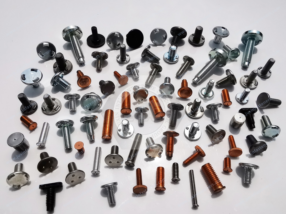
Projection welding can be understood as a sequence of mechanical contact, electrical heating, projection deformation, and controlled cooling.
[1. Squeeze Phase]
        ↓
Electrodes establish controlled contact
        ↓
[2. Heating Phase]
        ↓
Current passes through the projection area
        ↓
[3. Projection Collapse / Weld Formation]
        ↓
Projection deforms and the welded interface develops
        ↓
[4. Hold / Cooling Phase]
        ↓
Current stops while force is maintained
During the squeeze phase, the electrodes bring the weld fastener and sheet into controlled contact.
The applied electrode force has several functions:
Establishing stable electrical contact
Positioning the fastener against the sheet
Controlling the contact condition before current is applied
Supporting the projection during heating
Influencing how the projection deforms during welding
Insufficient or inconsistent electrode force can contribute to unstable electrical contact, premature expulsion, surface marking, or inconsistent weld formation.
Excessive force can also be problematic because it may alter the intended projection geometry before sufficient heating occurs.
The correct force therefore needs to be established for the specific fastener, material combination, projection geometry, electrode system, and welding equipment.
During the welding phase, electrical current passes through the joint.
The projection creates a deliberately localized contact condition. Because the electrical resistance and current density are concentrated around the projection area,
heat generation occurs preferentially in the intended weld region.
This is one of the fundamental differences between projection welding and simply pressing a flat fastener against a sheet and applying current.
The actual current distribution is influenced by:
Projection dimensions
Number of projections
Projection spacing
Sheet thickness
Fastener material
Sheet material
Surface condition
Electrode geometry
Electrical contact resistance
Welding current
Welding time
A stable process requires these factors to work together.
As localized heating progresses, the projection undergoes deformation.
The electrode force contributes to the controlled collapse of the projection while the interface develops the welded connection.
The objective is not simply to generate as much heat as possible. The objective is to generate the correct amount and distribution of heat while maintaining controlled mechanical contact.
If heat generation becomes excessive or unstable, molten material may be expelled from the interface. If insufficient energy reaches the intended weld region, incomplete weld development may occur.
Therefore, projection geometry is a critical part of weld fastener design.
After the welding current stops, electrode force may be maintained while the joint cools and the welded region develops its final structure.
Maintaining controlled force during this stage can help stabilize the joint and reduce movement before the weld has sufficiently cooled.
The appropriate hold conditions depend on the materials, geometry, welding system, and production process.
For high-volume OEM manufacturing, the squeeze, weld, and hold sequence should be validated together rather than optimized independently.
Projection welding is fundamentally a parameter-balance problem.
        WELDING CURRENT
              ↕
              │
ELECTRODE FORCE ←→ WELDING TIME
              │
              ↕
       PROJECTION GEOMETRY
              │
              ↓
       WELD DEVELOPMENT
| Parameter | Primary Function | If Too Low / Insufficient | If Too High / Excessive |
|---|---|---|---|
| Welding Current (I) | Provides electrical energy for localized heating | Insufficient heating or incomplete weld development | Excessive heating, expulsion, surface damage, or distortion |
| Electrode Force (F) | Maintains contact and controls projection deformation | Unstable contact, arcing, expulsion, or inconsistent welding | Premature projection deformation or altered heat-generation conditions |
| Weld Time (t) | Controls the duration of current application | Insufficient heat development | Excessive heat input or a larger affected area |
| Projection Geometry | Concentrates current and force at the intended weld locations | Poor current concentration or inconsistent weld development | Excessive local heating, deformation, or sheet damage |
| Electrode Geometry | Controls force and current delivery to the joint | Unstable or uneven contact | Excessive marking or altered current distribution |
A common mistake in production troubleshooting is to ask:
“What welding current should we use for this weld nut?”
There is no reliable universal answer without knowing the complete joint configuration.
The required welding schedule depends on the interaction between the fastener and the sheet.
For example, changing any of the following may require process revalidation:
Sheet thickness
Sheet grade
Fastener material
Fastener size
Projection geometry
Surface coating
Number of projections
Electrode configuration
Welding equipment
Electrical characteristics of the machine
This is why an OEM weld fastener supplier should receive the actual application information rather than only a nominal thread size.
Current density is particularly important because projection welding depends on concentrating electrical energy at specific locations.
If current distribution becomes unbalanced between multiple projections, the individual welds may not develop uniformly.
Potential causes include:
Unequal projection heights
Uneven sheet contact
Fastener distortion
Electrode misalignment
Surface contamination
Inconsistent material thickness
Poor fixture positioning
For multi-projection weld nuts and similar fasteners, maintaining consistent projection geometry is therefore an important manufacturing consideration.
A reliable projection-welded joint starts with the fastener and sheet-metal design.
Design engineers should consider the weld interface before finalizing the threaded feature, panel geometry, and assembly sequence.
Heat balance is the practical objective of ensuring that the projection, fastener, and sheet respond appropriately to the selected welding schedule.
The goal is to develop the required weld connection without unnecessarily damaging the surrounding sheet.
BALANCED JOINT

[ Weld Fastener ]
       ↓
   Projections
       ↓
====================  Sheet Metal
       ↓
Localized Weld Zone


POORLY BALANCED JOINT

[ Heavy Fastener ]
       ↓
Large / unsuitable projection
       ↓
====================  Thin Sheet
       ↓
Excessive local heating
or inadequate weld development
For a relatively heavy fastener attached to a thin sheet, projection design becomes especially important.
The fastener, projection, and sheet should be considered as a combined thermal and mechanical system rather than selecting a projection shape independently of the substrate.
Projection geometry influences:
Initial electrical contact area
Current concentration
Collapse behavior
Heat generation
Weld nugget development
Required electrode force
Repeatability between parts
The appropriate geometry depends on the fastener type and material combination.
For this reason, projection dimensions should be controlled as a manufactured feature rather than treated as a cosmetic detail.
For OEM production, the drawing should clearly define the critical projection features and the dimensional characteristics that affect welding performance.
Different material combinations can behave very differently during resistance welding.
Low-carbon steels are commonly used in projection-welded fastener applications because their electrical, thermal,
and metallurgical characteristics can support stable resistance welding when the joint is appropriately designed.
Stainless steels may require a different welding window because their electrical resistance, thermal behavior, surface condition, and electrode interaction differ from those of carbon steels.
High-strength steels and advanced high-strength steels (AHSS) require additional attention to heat input, cooling behavior, hardness changes, and the resulting weld-zone properties.
The important engineering principle is:
Do not transfer a welding schedule from one material system to another without validation.
Even when two sheets have the same nominal thickness, their welding behavior can differ because of differences in:
Electrical resistivity
Thermal conductivity
Surface coating
Material strength
Metallurgical structure
Surface condition
Surface treatment is another important factor in projection welding.
Zinc-coated steel, stainless steel, plated fasteners, and untreated materials can present different electrical contact conditions.
The coating must therefore be considered during weld-process development.
Important questions include:
Does the coating change contact resistance?
Will the coating affect electrode life?
Does the welding process require special electrode maintenance?
Is the coating compatible with the intended weld location?
Will the finished assembly require additional corrosion protection?
For OEM applications, the fastener finish should be selected together with the welding process rather than specified independently.
The surrounding sheet design can strongly influence weld consistency.
Engineers should examine:
Local sheet thickness
Flanges
Bends
Embossments
Holes
Slots
Nearby welds
Access for electrodes
Fastener seating surface
Potential panel deformation
A weld fastener may perform well in a flat test coupon but behave differently when installed close to a bend, flange, hole, or formed feature.
This is why representative production geometry should be included in process validation whenever practical.
When a fastener contains multiple projections, the objective is to develop a consistent welded connection across the intended projection locations.
Projection height consistency and fastener seating are therefore particularly important.
An imbalance may cause one projection to weld more strongly than another.
Possible contributors include:
Projection dimensional variation
Sheet flatness
Fastener orientation
Electrode alignment
Uneven pressure
Surface contamination
For high-volume production, projection consistency becomes a manufacturing-quality characteristic as well as a welding-process characteristic.
Projection-welded fasteners should be validated using tests appropriate to the application and the required joint performance.
There is no single universal acceptance value for every weld nut, weld stud, sheet thickness, and industry.
Instead, the inspection plan should be linked to the engineering specification, customer drawing, applicable standard, and validated production process.
Mechanical destructive testing can be used to evaluate the strength and failure mode of the welded attachment.
Depending on the fastener and joint design, the test may evaluate:
Axial attachment strength
Separation resistance
Weld-interface integrity
Parent-sheet deformation
Failure mode
The target test method and acceptance criteria should be established for the specific application.
For threaded weld nuts, rotational testing can be used to evaluate resistance to turning or detachment under the specified test conditions.
This is particularly relevant where the fastener must remain mechanically anchored while the mating screw is tightened or removed.
The appropriate torque test value should come from the product specification, customer requirement, validated design, or applicable standard—not from a generic value applied to every weld nut.
Cross-sectional inspection can provide information that cannot be obtained from an external visual inspection alone.
A metallographic section may be used to examine:
Weld-zone development
Nugget geometry
Fusion characteristics
Heat-affected regions
Internal discontinuities
Projection collapse
Sheet deformation
For process development and failure analysis, metallography can be particularly valuable because it helps engineers connect the external failure mode with the actual weld structure.
Production inspection should also consider the physical condition of the fastener and sheet.
Typical checks may include:
Fastener location
Fastener orientation
Projection condition
Thread condition
Surface marking
Visible expulsion
Sheet distortion
Electrode indentation
Weld appearance
Dimensional inspection is especially important when the fastener interfaces with automated downstream assembly equipment.
For automated OEM production, process monitoring can provide an additional layer of control.
Depending on the welding equipment, the process may be monitored through characteristics such as:
Welding current
Welding time
Electrode force
Electrical resistance
Electrode displacement
Weld-force response
The exact monitoring strategy depends on the production equipment and quality requirements.
The objective is not simply to record machine parameters. The objective is to detect process drift before it becomes a recurring assembly failure.
Expulsion occurs when molten material is expelled from the weld region.
Potential contributors include:
Excessive heat input
Insufficient or unstable electrode force
Poor projection geometry
Contaminated surfaces
Excessive contact resistance
Improper current distribution
Incorrect welding schedule
Rather than reducing current automatically, engineers should determine which part of the electrical-mechanical balance is causing the instability.
Insufficient weld development can result from:
Inadequate heat generation
Poor projection contact
Incorrect projection geometry
Insufficient weld time
Inappropriate electrode conditions
Surface contamination
Incorrect material assumptions
A process that appears visually acceptable may still require destructive testing to verify the actual weld connection.
Fastener deformation can occur when the mechanical and thermal conditions are not properly balanced.
Potential causes include:
Excessive electrode force
Unsuitable projection geometry
Excessive heat input
Poor fastener support
Misaligned electrodes
This can become particularly important for threaded fasteners because distortion of the thread or body may affect downstream assembly.
Thin sheet applications require careful control because excessive localized heat or mechanical force can damage the substrate.
The solution may involve changes to:
Projection design
Welding schedule
Electrode configuration
Fastener geometry
Sheet design
Process sequence
The correct solution should be established through joint-specific validation rather than by applying one universal parameter adjustment.
One of the most important DFM principles for OEM weld fasteners is that fastener design and welding-process design should not be separated.
The following elements should be considered together:
FASTENER DESIGN
      ↓
Projection Geometry
      ↓
Material & Finish
      ↓
SHEET-METAL DESIGN
      ↓
Electrode Configuration
      ↓
WELDING PARAMETERS
      ↓
QUALITY VALIDATION
      ↓
MASS PRODUCTION
A change to any upstream element may affect the downstream process.
For example, changing the fastener material or plating may alter electrical contact conditions.
Changing projection geometry may change the required welding window. Changing sheet thickness may affect heat distribution.
This is why early supplier involvement can reduce repeated tooling and process-development work.
Before releasing a weld fastener for mass production, OEM engineering and procurement teams should review the following.
Fastener type
Thread specification
Fastener dimensions
Projection number
Projection geometry
Critical projection dimensions
Material
Surface treatment
Corrosion requirements
Required mechanical performance
Sheet material
Sheet thickness
Surface coating
Local forming features
Available weld area
Electrode access
Fastener orientation
Distance from bends and holes
Downstream assembly requirements
Welding equipment
Electrode configuration
Current control
Electrode force control
Welding time
Hold conditions
Process monitoring
Electrode maintenance
Production validation method
Visual inspection
Dimensional inspection
Thread inspection
Axial mechanical testing where required
Torque testing for weld nuts where required
Cross-sectional analysis during validation
Defined failure criteria
Traceability requirements
This checklist gives procurement teams a much more useful RFQ framework than specifying only “M6 weld nut” or “weld stud.”
For an OEM weld fastener supplier, the quality of the RFQ directly affects the quality of the engineering response.
A useful RFQ should include:
Fastener drawing
Thread specification
Fastener material requirement
Surface treatment requirement
Projection geometry
Sheet material
Sheet thickness
Welding method
Production volume
Application environment
Required mechanical performance
Applicable customer or industry standards
Inspection requirements
Packaging requirements
Annual demand and delivery expectations
If the fastener is intended for automated resistance welding, it is particularly useful to provide the actual mating sheet material and production process information.
This allows the supplier to evaluate the fastener as part of the complete joint rather than treating it as an isolated catalog component.
JUXIN FASTENERS supplies OEM-oriented fastening components for sheet-metal assembly and industrial applications.
Our weld fastener scope can include:
Weld nuts
Projection weld nuts
Weld studs
Weld pins
Custom weld fasteners
Special threaded fastening components
Custom-machined fastening components
For projects involving resistance projection welding, engineering considerations can include:
Fastener geometry
Projection configuration
Material selection
Surface treatment
Drawing review
DFM evaluation
Production requirements
Inspection requirements
OEM packaging and supply requirements
The objective is to develop a fastener that works with the customer's manufacturing process—not simply to supply a nominal thread size.
For OEM buyers, procurement engineers, and welding-process engineers, early technical communication can help identify potential problems before production tooling and validation are completed.
Weld spatter, also called expulsion, occurs when the thermal and mechanical conditions at the weld interface become unstable and molten material is expelled.
Potential contributors include excessive heat input, insufficient or unstable electrode force, poor projection geometry, surface contamination, and uneven current distribution.
The correct corrective action should be determined from the specific welding system rather than assuming that current alone is responsible.
Projection welding is particularly suitable for fasteners because the projection is intentionally incorporated into the fastener geometry.
This allows the weld location to be concentrated around the projection while the fastener itself becomes part of the welded joint.
For multi-projection fasteners, multiple weld locations may also be developed within the same welding operation, depending on equipment and joint design.
The welding parameters depend on the fastener material, sheet material, sheet thickness, projection geometry, surface condition, electrode configuration, welding equipment, and required joint performance.
There is no single current, force, or time value that should be universally applied to every projection weld nut.
Yes, stainless steel can be used in projection-welded fastener applications, but the welding process must be developed for the specific stainless-steel grade, mating sheet, surface condition, electrode system, and production requirements.
A welding schedule developed for carbon steel should not automatically be transferred to stainless steel.
Verification can combine visual and dimensional inspection with application-specific destructive and metallurgical testing.
Depending on the application, this may include axial testing, torque-out testing for weld nuts, cross-sectional analysis, process monitoring, and dimensional inspection.
The acceptance criteria should be defined by the engineering specification, customer requirement, or applicable standard.
The most useful information includes the fastener drawing, thread specification, material, surface treatment, projection requirements, mating sheet material and thickness, welding method, production volume, application environment, quality requirements, and applicable standards.
Providing this information early allows the weld fastener supplier to evaluate both manufacturing feasibility and welding-process compatibility.
Need support selecting or developing a projection weld fastener for your sheet-metal assembly?
Send your technical inquiry, drawing, fastener specification, mating sheet material, and application requirements to the JUXIN FASTENERS engineering team.
Email: info@juxinfasteners.com
JUXIN FASTENERS provides OEM weld fasteners and engineering-oriented DFM support for industrial sheet-metal assembly applications.
Precision Fastening Solutions Since 2003
Product Packaging
Packaging Standard
At Juxin Fasteners, we apply standardized export packaging to ensure product protection, traceability, and compliance with international logistics requirements.
1. Standard Export Packaging
Unless otherwise specified, all products will be packed according to our factory standard export packaging, which includes:
Moisture-resistant inner protection
Poly bag or small box packing as required
Reinforced export cartons
Clear labeling with part number, specification, batch number, and quantity
Palletizing for sea or air shipment when necessary
Our standard packaging is designed to ensure safe transportation, efficient warehousing, and long-distance international shipping.
2. Customized Packaging Options
We also provide customized packaging solutions according to customer requirements, including but not limited to:
Private labeling
Customized barcodes
Specific carton dimensions
Retail packaging
Special pallet configuration
Customer-specific marking and identification
So that you know, customized packaging may involve additional costs and extended lead time depending on the complexity of the requirements.
3. Compliance & Quality Assurance
All packaging processes are controlled under our ISO 9001 quality management system to ensure consistency, traceability, and product integrity throughout the supply chain.
Product Pictures
Hot Products
Contact Us
Tel.:
+86 020 8621 0320
+86 020 3121 6067
E-mail:
Technical Support:
Navigation
SEND INQUIREY