Call Us
+86 136 6007 9809
Call Us
+86 136 6007 9809

What is the difference between weld nuts and blind rivet nuts?
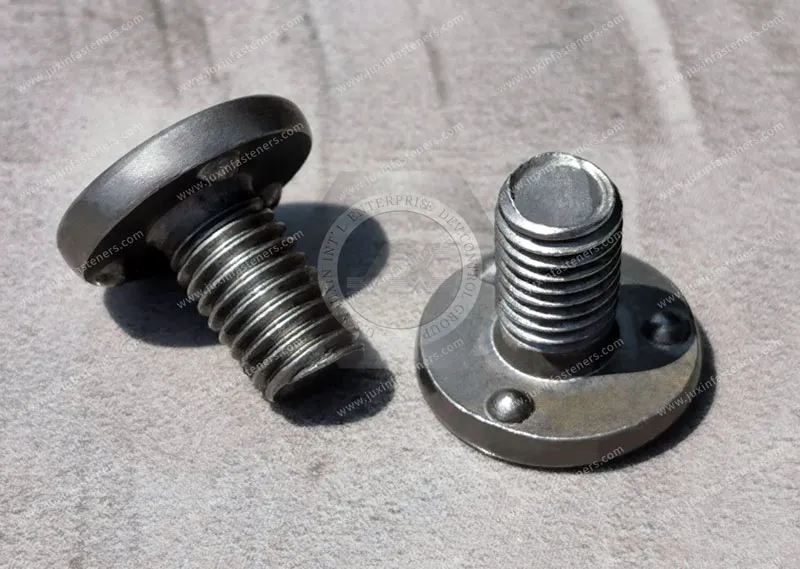
Weld nuts are attached to metal components through resistance welding, commonly resistance projection welding.
The fastener incorporates projections that concentrate electrical current and electrode force at defined locations.
During the welding process, localized heating and controlled projection deformation create a welded connection between the fastener and the sheet.
Product Specification
What is the difference between weld nuts and blind rivet nuts?
Weld nuts are attached to metal components through resistance welding, commonly resistance projection welding.
The fastener incorporates projections that concentrate electrical current and electrode force at defined locations.
During the welding process, localized heating and controlled projection deformation create a welded connection between the fastener and the sheet.
Blind rivet nuts, also called rivet nuts or threaded inserts, are installed mechanically from one side of the workpiece.
A pull tool engages the internal thread or mandrel system and deforms the tubular body of the rivet nut behind the sheet,
creating a mechanical clamping region that retains the threaded insert in the prepared hole.
The fundamental difference is therefore not simply “welded versus mechanical.”
It is also:
Two-sided welding access versus single-sided blind installation.
 WELD NUT                                      BLIND RIVET NUT

  [ Upper Electrode ]                           [ Pull Tool / Mandrel ]
          ↓                                               ↓
    +-----------+                                  +-------------+
    |  WELD NUT |                                  | RIVET NUT   |
    +--[PROJ.]--+                                  +-------------+
          ↓                                               ↓
===========================                    ===========================
        SHEET METAL                                  SHEET METAL
          ↑                                               ↑
  [ Lower Electrode ]                            [ Collapsed / Bulged
                                                    Sleeve Section ]
Weld nuts generally require access for the welding electrodes and an appropriate resistance-welding process.
Blind rivet nuts are specifically valuable when the rear side of the sheet cannot be accessed during installation, such as in:
Hollow structural sections
Closed tubes
Box sections
Enclosures
Assemblies with restricted backside access
Existing finished assemblies
Field or maintenance applications
Engineers may consider weld nuts when the assembly architecture supports resistance welding and the joint requirements, material combination, and production process are compatible with welded fastening.
Blind rivet nuts may be preferred when single-sided installation is the dominant design constraint, even when a welded fastener might otherwise offer attractive mechanical performance.
Neither technology should be selected solely because one is described as “heavy duty” or the other as “light duty.”
Actual joint performance depends on:
Fastener geometry
Fastener material
Sheet material
Sheet thickness
Joint geometry
Hole design
Installation or welding process
Loading direction
Dynamic loading
Environmental conditions
Surface treatment
Manufacturing consistency
For OEM design teams, the first question should therefore be:
Which joining method best fits the physical access, joint performance, manufacturing process, and lifecycle requirements of the assembly?
JUXIN FASTENERS supplies weld nuts, weld studs, and other industrial fastening components for OEM sheet-metal applications,
with engineering support focused on application requirements and manufacturability.
The two technologies create retention through fundamentally different mechanisms.
                     JOINT MECHANICS COMPARISON

                 WELD NUTS
                     ↓
       Resistance Projection Welding
                     ↓
        Localized Welded Connection
                     ↓
             Sheet Metal Joint


              BLIND RIVET NUTS
                     ↓
       Mechanical Sleeve Deformation
                     ↓
       Backside Clamping / Interlock
                     ↓
             Sheet Metal Joint
| Parameter | Weld Nuts (JUXIN FASTENERS) | Blind Rivet Nuts |
|---|---|---|
| Access Requirements | Two-sided access is generally required for electrode positioning and force application | Single-sided installation capability |
| Joining Mechanism | Resistance projection welding at designed projection locations | Mechanical deformation of the tubular body to form a backside retaining section |
| Push-Out Resistance | Depends on weld design, sheet properties, projection geometry, and welding-process quality | Depends on rivet-nut geometry, sheet properties, hole condition, installation quality, and backside formation |
| Torque-Out Resistance | Depends on weld configuration, fastener geometry, projection design, and weld quality | Depends on body geometry, anti-rotation features, sheet properties, installation condition, and fastener design |
| Hollow Structural Sections | Difficult where the rear side is inaccessible to welding electrodes | Well suited to closed tubes, hollow sections, and restricted-access assemblies |
| Installation Process | Resistance welding | Mechanical pull-tool installation |
| Heat During Installation | Localized welding heat is intentionally generated | No resistance-welding heat is required |
| Surface-Finish Sequence | Often integrated into a raw-sheet welding and subsequent coating process, depending on the production architecture | Can be useful where installation after finishing is required, subject to the panel and coating requirements |
| Production Automation | Well suited to automated resistance-welding systems | Well suited to controlled mechanical installation systems |
| Process Validation | Requires validation of welding parameters and joint performance | Requires validation of hole, installation process, and joint performance |
| Serviceability | Typically treated as a permanently attached welded fastener | Can provide a threaded attachment where access is available from only one side |
| Best-Known Design Advantage | Integration into welded sheet-metal production | Single-sided installation in inaccessible locations |
For many OEM designs, access rather than theoretical strength determines the initial choice.
If both sides of the panel are accessible and resistance welding can be integrated into the production process, a weld nut may be a practical solution.
If the rear side is enclosed, blocked, or inaccessible, a blind rivet nut may provide a major manufacturing advantage because the threaded attachment can be installed from the accessible side.
This is particularly important in:
Closed box sections
Tubular structures
Extrusions
Electrical enclosures
HVAC housings
Equipment frames
Vehicle structures
Assemblies that cannot be turned over during installation
The access constraint should be identified early in the DFM process.
A common mistake is to describe one technology as universally stronger.
In reality, push-out and torque-out performance depend on the complete joint.
For a weld nut, relevant variables include:
Projection geometry
Number of projections
Fastener material
Sheet material
Sheet thickness
Welding current
Welding time
Electrode force
Electrode configuration
Surface condition
For a blind rivet nut, relevant variables include:
Body geometry
Flange geometry
Sleeve design
Hole diameter
Hole quality
Sheet thickness
Sheet material
Installation stroke
Installation force
Tooling
Anti-rotation geometry
Therefore, catalog-level comparisons should be treated as a starting point rather than a substitute for application validation.
The following decision framework can help engineers determine which technology should be evaluated first.
                     START: STRUCTURAL THREAD SELECTION
                                    |
                                    ↓
               Is backside access blocked or restricted?
                    /                         \
                  YES                         NO
                   ↓                           ↓
       Evaluate BLIND RIVET NUT        Can resistance welding
             as first option            be integrated into production?
                                              /          \
                                            YES           NO
                                             ↓             ↓
                                      Evaluate WELD NUT   Evaluate
                                             ↓           mechanical
                                             ↓           alternatives
                                Are joint performance,
                                environment, and DFM
                                requirements satisfied?
                                      /       \
                                    YES        NO
                                     ↓          ↓
                              WELD NUT       Compare
                                           alternatives
The important point is that the decision tree should be based on actual manufacturing constraints and joint requirements, not simply on a generic thickness threshold.
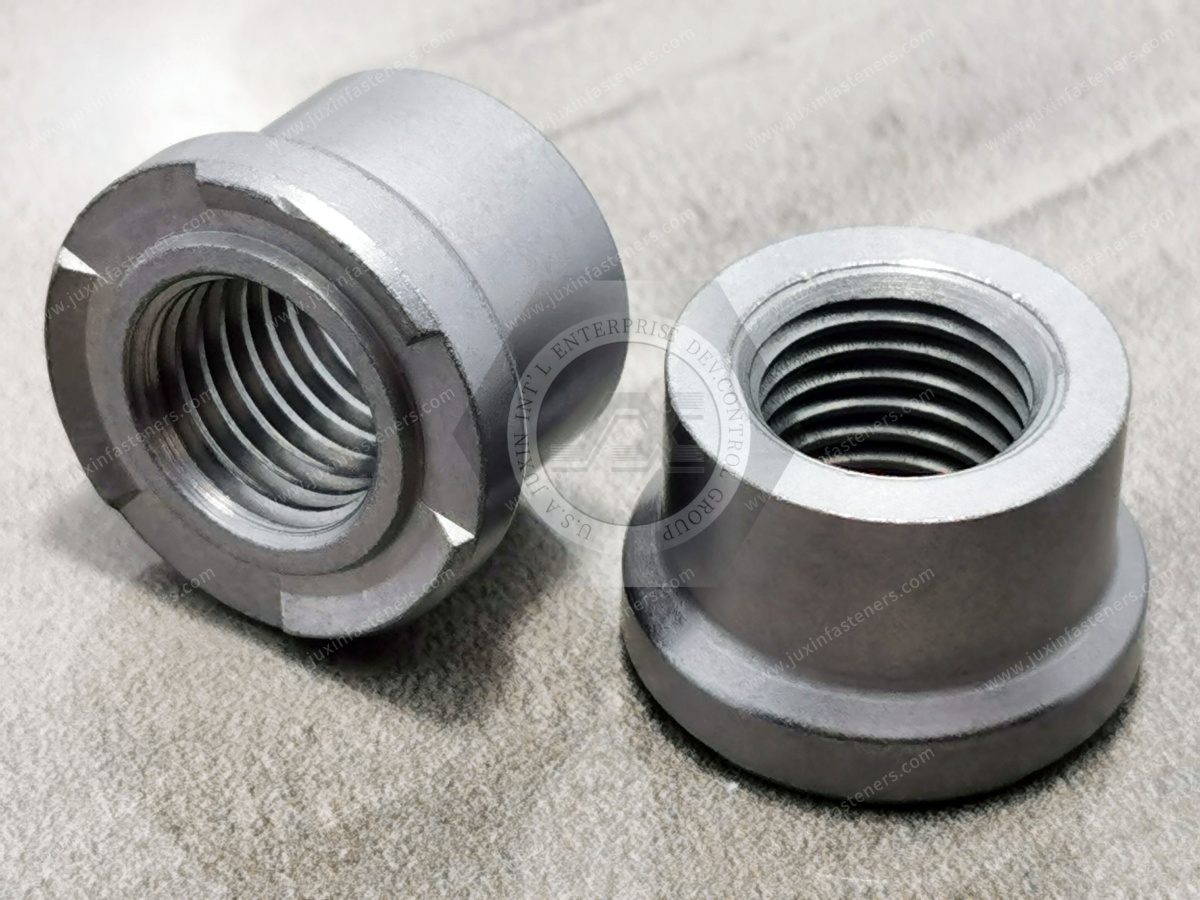
Weld nuts can be considered for applications where:
Both sides of the sheet are accessible
The substrate is suitable for resistance welding
The production line already incorporates resistance welding
The threaded attachment needs to be integrated into a welded sheet-metal assembly
The welding operation can be completed before subsequent coating or assembly operations
The required mechanical performance is compatible with the welded joint design
Potential applications include:
Automotive sheet-metal assemblies
Structural brackets
Industrial machinery
Equipment frames
Electrical cabinets
HVAC equipment
Appliance structures
Power equipment enclosures
Fabricated steel components
For automated production, resistance welding can also provide repeatable attachment when the fastener geometry, electrode system, fixture, and welding process are properly controlled.
The key requirement is not simply that welding is available.
The fastener, sheet, electrode system, and welding schedule must be compatible with one another.
Blind rivet nuts are particularly useful when the assembly can only be accessed from one side.
Typical applications include:
Enclosed hollow structural sections
Tubing
Pipes
Box beams
Closed channels
Equipment housings
Electrical enclosures
Vehicle structures
Field-installed components
Maintenance assemblies
They can also be useful where bringing a resistance-welding electrode to the backside of the panel would be impractical.
For field maintenance or low-volume installation, portable pull tools can provide additional flexibility compared with a fixed resistance-welding cell.
However, the selected rivet nut must still be matched to:
Sheet material
Sheet thickness
Hole size
Hole tolerance
Flange geometry
Required thread size
Required pull-out performance
Required torque-out performance
Installation equipment
Weld nuts can be highly attractive in automated production environments where resistance welding is already part of the manufacturing sequence.
Potential benefits include:
Integration with robotic welding systems
Repeatable fastener positioning
Automated fixture loading
Multiple projection weld locations
Integration before coating
Reduced need for a separate mechanical insert-installation operation
However, the production system also needs to account for:
Electrode access
Electrode maintenance
Weld-process monitoring
Spatter control
Thread protection
Fixture positioning
Panel distortion
Process validation
Blind rivet nuts can simplify assembly when access is available from only one side.
The installation process generally involves:
1. Prepare Hole
       ↓
2. Insert Rivet Nut
       ↓
3. Engage Installation Tool
       ↓
4. Deform Sleeve
       ↓
5. Form Backside Retaining Section
       ↓
6. Release Tool
       ↓
7. Inspect Installed Fastener
The installation process should be controlled because insufficient or excessive deformation can affect the final joint.
For high-volume production, installation tooling and process monitoring should be evaluated as part of the complete manufacturing system.
Gemini's original draft gave universal cycle-time values for both technologies.
Those numbers should not be treated as engineering specifications.
Actual installation time depends on:
Equipment
Fastener size
Fastener geometry
Number of operations
Automation
Fixture design
Operator handling
Welding schedule
Tooling
Production sequence
For procurement decisions, measured cycle time in the actual production environment is more meaningful than a generic catalog value.
A meaningful cost comparison should include more than the fastener unit price.
TOTAL INSTALLED COST

Fastener
   +
Tooling
   +
Equipment
   +
Labor / Automation
   +
Fixtures
   +
Process Inspection
   +
Maintenance
   +
Scrap / Rework
   +
Production Cycle Impact
   +
Coating / Finishing Sequence
   =
Total Manufacturing Cost
For example, a weld nut may be attractive when the production line already contains resistance-welding equipment.
A blind rivet nut may be more economical when adding welding equipment would require significant capital investment or when the assembly is inaccessible to welding electrodes.
The correct comparison is therefore the total installed cost for the actual production process.
This is one of the clearest application differences between the two technologies.
A closed tube or box section may prevent access to the backside of the sheet.
In such a design:
        CLOSED SECTION

     ┌─────────────────┐
     │                 │
     │     THREAD      │ ← Accessible side
     │      ●          │
     │                 │
     └─────────────────┘
             X
        No electrode
        access to rear
A blind rivet nut can be installed from the accessible side because the installation tool creates the retaining deformation internally.
A weld nut generally requires a fundamentally different assembly strategy if conventional two-sided electrode access is unavailable.
This makes blind rivet nuts particularly valuable in closed or hollow structures.
For structural applications, engineers should not select between the two technologies based solely on the word “structural.”
The actual load path should be evaluated.
Important questions include:
Is the primary load axial?
Is there a significant torque load?
Is the joint subject to cyclic loading?
Is vibration present?
Is the sheet locally reinforced?
Is the threaded fastener close to an edge?
Does the sheet deform before the fastener fails?
What failure mode is acceptable?
The limiting component may be:
Fastener
Weld
Rivet-nut body
Sheet metal
Hole
Bracket
Mating screw
Surrounding structure
Therefore, the strongest threaded insert does not automatically create the strongest assembly.
If the joint will be repeatedly assembled and disassembled, thread condition and attachment stability become important.
For a weld nut, the welded attachment is generally intended to remain permanently attached to the panel.
For a blind rivet nut, the threaded insert also remains installed, but its mechanical retention depends on the deformation and interaction between the insert and sheet.
Repeated bolt installation should therefore be included in the application-specific validation plan where serviceability is important.
Before specifying a weld nut, review:
Fastener geometry
Projection design
Number and location of projections
Sheet material
Sheet thickness
Surface condition
Electrode access
Electrode configuration
Fastener orientation
Nearby holes
Bends and flanges
Existing welds
Coating sequence
Thread protection
The weld nut should be designed as part of the resistance-welding process.
For blind rivet nuts, the hole becomes a critical part of the fastening system.
Review:
Hole diameter
Hole tolerance
Hole shape
Sheet thickness
Sheet material
Sheet ductility
Edge distance
Flange clearance
Installation access
Tool access
Required grip range
Fastener body geometry
Anti-rotation requirements
A poorly controlled hole can cause installation problems even when the rivet nut itself is manufactured correctly.
Blind rivet nuts depend directly on the prepared hole.
Potential issues include:
Hole too large
Hole too small
Out-of-round hole
Burrs
Cracks
Damaged coating
Incorrect hole position
Excessive variation
The hole should therefore be included in the DFM and quality-control plan rather than treated as an unrelated sheet-metal feature.
Potential weld-nut failure modes include:
Weld separation
Insufficient weld development
Weld spatter
Projection inconsistency
Sheet tearing
Fastener deformation
Thread damage
Incorrect fastener position
Panel distortion
Failure analysis should determine whether the limiting mechanism is the weld, fastener, sheet, or surrounding structure.
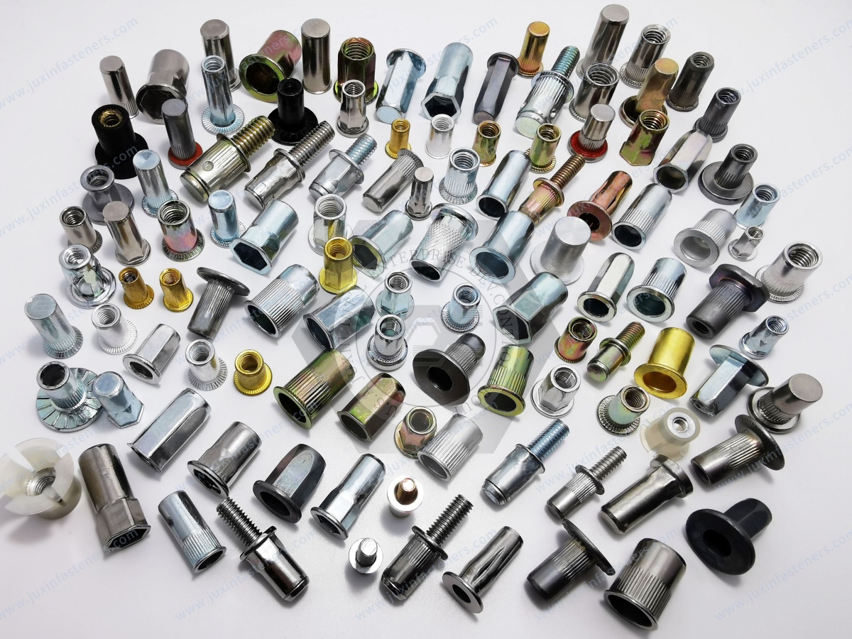
Potential blind rivet nut failure modes include:
Spinning during bolt installation
Pull-out
Excessive deformation
Insufficient backside formation
Sheet cracking
Hole enlargement
Incorrect grip condition
Thread damage
Flange deformation
A spinning rivet nut is particularly inconvenient during final assembly because the insert may rotate with the mating bolt.
The prevention strategy may involve selecting a different rivet-nut body geometry, improving hole control, changing installation conditions, or selecting a fastener with stronger anti-rotation characteristics.
The original comparison can be misleading if it suggests that all blind rivet nuts are inherently susceptible to spinning.
Different blind rivet nut designs use different body geometries and anti-rotation mechanisms.
Depending on the product, these may include:
Knurled bodies
Hexagonal bodies
Specialized anti-rotation features
Flange designs
Application-specific body configurations
Therefore, engineers should compare the actual rivet-nut design rather than treating all blind rivet nuts as one category.
Procurement teams should compare the technologies according to the production system and application.
| Procurement Factor | Weld Nuts | Blind Rivet Nuts |
|---|---|---|
| Fastener Unit Cost | Application-dependent | Application-dependent |
| Installation Equipment | Resistance-welding equipment | Mechanical pull-tool system |
| Backside Access | Generally required for conventional electrode access | Not required |
| Installation Heat | Localized resistance-welding heat | No resistance-welding heat |
| Hollow Sections | Challenging without electrode access | Particularly suitable |
| Automation | Suitable for automated welding cells | Suitable for automated or semi-automated installation |
| Process Validation | Welding-process and joint validation | Installation-process and joint validation |
| Hole Requirement | Fastener projections contact the sheet | Controlled prepared hole required |
| Surface-Finish Sequence | Often welded before coating where appropriate | Can be installed later depending on finish and assembly requirements |
| Maintenance / Field Installation | Generally requires welding equipment | Portable installation tools can provide greater flexibility |
| Best Selection Method | Joint-specific engineering evaluation | Joint-specific engineering evaluation |
For OEM sourcing, the supplier should be capable of discussing the complete application rather than quoting only a thread size.
Useful supplier capabilities include:
Technical drawing review
DFM analysis
Material selection
Weld projection design
Rivet-nut body selection
Surface-treatment recommendations
Prototype development
Sample testing
Dimensional inspection
Mechanical validation
Production quality control
OEM packaging
Global supply coordination
This becomes particularly important for custom fasteners or applications where the fastening component is integrated into a larger automated production system.
Pillar Solution Page: JUXIN FASTENERS Weld Fasteners Solutions
Product Category Page: JUXIN FASTENERS Projection Weld Nuts
Engineering Guide: Hexagonal Weld Nuts Engineering & Sourcing Guide
Engineering Guide: Weld Nuts vs. Self-Clinching Nuts Selection Guide
Commercial Sourcing Page: Consult JUXIN FASTENERS Fastener Engineers
These related pages should form an internal-link structure connecting the weld-fastener solution category, projection weld nut products, comparative engineering guides, and OEM sourcing pages.
It can be engineered to provide substantial torque resistance, but there is no universal value that allows all blind rivet nuts to be directly equated with all hexagonal weld nuts.
The actual torque-out performance depends on:
Fastener geometry
Sheet material
Sheet thickness
Hole size
Installation condition
Anti-rotation design
Weld quality, in the case of weld nuts
Loading condition
A properly designed blind rivet nut may be suitable for demanding applications where single-sided access is required.
A weld nut may provide a different and potentially advantageous load path where resistance welding is practical.
For critical applications, the two technologies should be compared using the same test method and application-specific acceptance criteria.
If a blind rivet nut loses its anti-rotation retention and rotates with the mating bolt, the bolt may become difficult to install or remove.
Depending on the assembly, corrective action can be difficult once the panel has been completed.
This is why the rivet-nut body design, hole condition, sheet properties, and installation process should be validated before production release.
For applications with significant torque requirements, engineers should specifically evaluate torque-out resistance rather than assuming that a standard rivet nut will provide sufficient anti-rotation performance.
A blind rivet nut is often the more practical technology when the backside of the closed section cannot be accessed.
The primary advantage is single-sided installation.
A weld nut can still be considered if the structure is designed with suitable access for welding electrodes or if the fastening process is performed before the section is closed.
The assembly sequence therefore matters as much as the fastener itself.
No.
Blind rivet nuts are available in different materials, body geometries, thread sizes, grip ranges, and anti-rotation configurations.
Their suitability depends on the actual application requirements and validated joint performance.
Engineers should evaluate the complete load path instead of categorizing every blind rivet nut as light duty.
Conventional resistance projection welding normally requires suitable access for the welding electrodes and force application.
If the rear side of the panel is completely inaccessible, a conventional weld-nut process may not be practical.
This is one of the situations where blind rivet nuts or another single-sided fastening technology may offer a manufacturing advantage.
Neither technology has one universal installation time.
Actual production cycle time depends on equipment, fastener size, welding schedule, tooling, automation, part handling, fixture design, and assembly sequence.
For a meaningful comparison, OEMs should conduct a process-level evaluation using the actual production equipment and part geometry.
Yes, blind rivet nuts can be used in selected aluminum sheet applications.
However, the aluminum grade, temper, sheet thickness, hole condition, rivet-nut material, body geometry, grip range, and installation process should be evaluated.
The fastener should be selected according to the actual aluminum substrate rather than assuming that every rivet nut is suitable for every aluminum sheet.
A useful RFQ should include:
2D drawing
Thread specification
Fastener dimensions
Fastener material
Surface treatment
Sheet material
Sheet thickness
Hole specification
Access limitations
Application loads
Temperature environment
Corrosion environment
Assembly process
Production volume
Quality requirements
Applicable standards
Packaging requirements
Providing this information allows the supplier to evaluate the fastening component as part of the complete assembly.
Need engineering guidance selecting between weld nuts, blind rivet nuts, or another threaded fastening technology for your production line?
Send your application details, 2D drawings, sheet-metal specifications, access requirements, and annual quantities to the JUXIN FASTENERS engineering team.
Email: info@juxinfasteners.com
JUXIN FASTENERS supports global OEM manufacturers with weld nuts, weld studs, threaded inserts, blind rivet nuts, custom fastening components, DFM evaluation, sample development, and production sourcing.
Whether the priority is resistance-welding integration, single-sided installation, structural attachment, automation, or total manufacturing cost,
the correct fastening technology should be selected from the complete engineering and production requirements.
Precision Fastening Solutions Since 2003
Product Packaging
Packaging Standard
At Juxin Fasteners, we apply standardized export packaging to ensure product protection, traceability, and compliance with international logistics requirements.
1. Standard Export Packaging
Unless otherwise specified, all products will be packed according to our factory standard export packaging, which includes:
Moisture-resistant inner protection
Poly bag or small box packing as required
Reinforced export cartons
Clear labeling with part number, specification, batch number, and quantity
Palletizing for sea or air shipment when necessary
Our standard packaging is designed to ensure safe transportation, efficient warehousing, and long-distance international shipping.
2. Customized Packaging Options
We also provide customized packaging solutions according to customer requirements, including but not limited to:
Private labeling
Customized barcodes
Specific carton dimensions
Retail packaging
Special pallet configuration
Customer-specific marking and identification
So that you know, customized packaging may involve additional costs and extended lead time depending on the complexity of the requirements.
3. Compliance & Quality Assurance
All packaging processes are controlled under our ISO 9001 quality management system to ensure consistency, traceability, and product integrity throughout the supply chain.
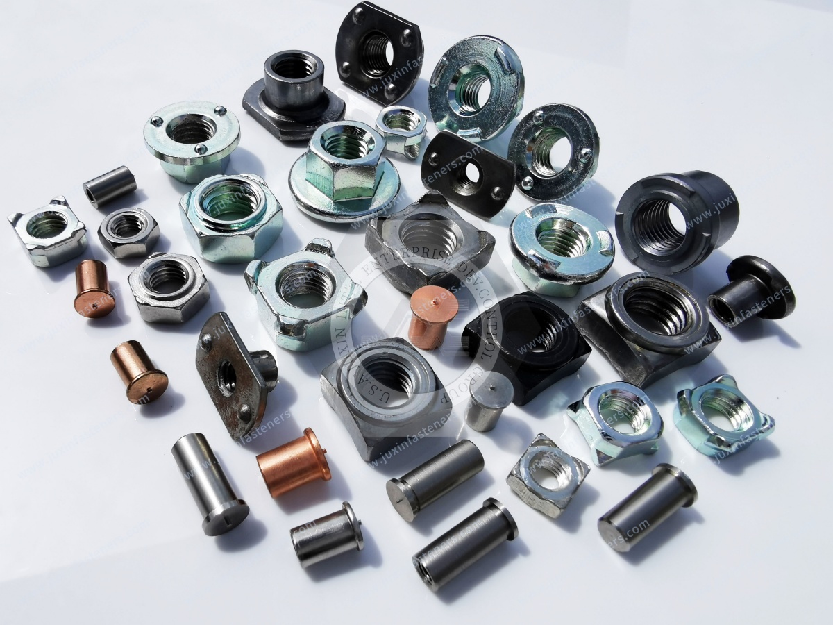
Product Pictures
Contact Us
Tel.:
+86 020 8621 0320
+86 020 3121 6067
E-mail:
Technical Support:
Navigation
SEND INQUIREY