Call Us
+86 136 6007 9809
Call Us
+86 136 6007 9809

What causes weld nut spin-out failure during bolt tightening, and how can engineers prevent it?
Weld nut spin failure, also called weld nut rotation failure or torque-out failure, occurs when the welded connection between a nut and
its sheet-metal substrate cannot withstand the rotational load generated during bolt installation or service.
Product Specification
What causes weld nut spin-out failure during bolt tightening, and how can engineers prevent it?
Weld nut spin failure, also called weld nut rotation failure or torque-out failure,
occurs when the welded connection between a nut and its sheet-metal substrate cannot withstand the rotational load generated during bolt installation or service.
The failure does not necessarily originate from the threaded nut itself. In many cases, the critical weakness is at the welded interface between the weld nut and parent sheet.
Potential causes include:
incomplete projection collapse;
insufficient or poorly distributed weld energy;
electrode misalignment;
electrode wear;
inappropriate electrode force;
current shunting;
contaminated or inconsistent joining surfaces;
unsuitable projection geometry;
excessive sheet deformation;
inadequate fixture rigidity;
incorrect welding sequence;
fastener or substrate material incompatibility;
installation torque exceeding the validated weld-joint capability.
Resistance projection welding generates localized heating at the projections where electrical resistance and contact conditions concentrate the welding process.
As the projections collapse and a weld nugget forms, the resulting joint must develop sufficient interface strength to resist the rotational and other loads imposed during assembly and service.
A useful engineering model is:
[ Bolt Installation Torque ]
              |
              v
[ Rotational Load Applied to Weld Nut ]
              |
              v
[ Weld Interface + Parent Sheet + Nut Geometry ]
              |
       ┌──────┴──────┐
       v             v
[ Adequate Joint ] [ Weakest Failure Path ]
[ Capacity ]        |
                    v
          [ Spin / Rotation Failure ]
                    |
                    v
        [ Root-Cause Investigation ]
                    |
                    v
     [ Fastener + Welding + DFM Correction ]
The important engineering point is that weld nut spin-out is a joint-system failure, not simply a fastener failure.
The correct corrective action therefore may involve the weld nut, projection design, parent sheet, welding process, electrode configuration, fixture, coating condition, installation torque, or several of these factors together.
JUXIN FASTENERS supplies weld nuts and other engineered fastening components for industrial applications where fastener geometry,
substrate material, joining process, quality control, and production requirements must be evaluated as one system.
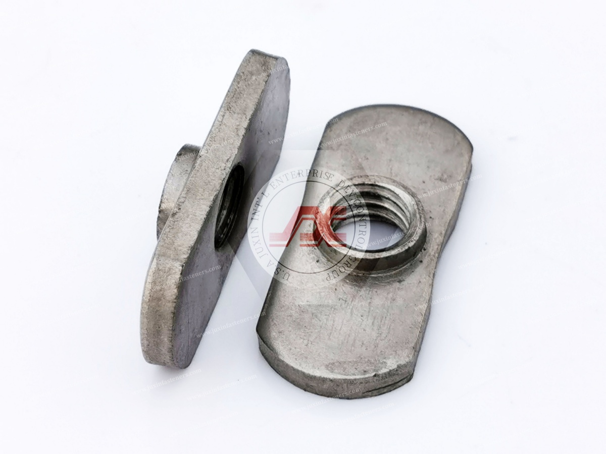
A common troubleshooting mistake is to assume that weld nut spin failure is caused simply by excessive bolt tightening torque.
That explanation is incomplete.
A weld nut can rotate because the weld interface is weaker than the applied installation load, but the reason for that weakness can originate much earlier in the manufacturing process.
The most useful diagnostic approach is therefore to separate the failure into several potential mechanisms.
Resistance projection welding depends on the interaction between:
electrical current;
contact resistance;
electrode force;
welding time;
material properties;
projection geometry;
surface condition;
sheet thickness;
fixture conditions.
The commonly used relationship:
Q = I²Rt
helps explain why current, resistance, and welding time influence heat generation.
However, this relationship should not be interpreted as a universal production formula from which one can determine a weld schedule without testing.
Actual weld development depends on the complete welding system.
Current shunting occurs when some welding current takes an unintended electrical path rather than contributing effectively to the intended weld interface.
This can become important when:
adjacent welds are too close;
geometry creates alternative conductive paths;
fixture or electrode arrangements alter current flow;
multiple conductive contact paths exist.
The result can be insufficient heating at the intended projection interface.
Electrode alignment can affect how force is distributed across the projections.
If the electrodes are not appropriately aligned with the weld nut and substrate, one projection may receive different mechanical or electrical conditions from another.
This can contribute to:
uneven projection collapse;
localized heating;
incomplete fusion;
asymmetric weld nugget formation;
inconsistent rotational resistance.
Electrode alignment should therefore be evaluated as part of the process rather than treated as a cosmetic tooling issue.
Electrode wear can change:
contact geometry;
current density distribution;
force distribution;
electrical contact conditions.
For high-volume production, electrode maintenance and dressing practices can therefore become important elements of weld fastener quality control.
Oil, scale, excessive oxide, dirt, incompatible coating residues, or other surface conditions can alter electrical and thermal behavior at the weld interface.
The correct response is not necessarily to increase welding current.
The manufacturing team should first determine whether the surface condition itself is outside the intended process window.
The projections on a weld nut are designed to concentrate the resistance welding process at controlled contact points.
Projection geometry can influence:
current concentration;
initial contact area;
electrode force distribution;
projection collapse;
heat generation;
nugget formation;
final joint geometry.
If projection geometry varies excessively, the welding process can become less repeatable.
This is why weld nut quality should not be evaluated only by overall nut dimensions.
For OEM applications, the projection features may represent critical functional characteristics.
The parent sheet is part of the welding system.
If the sheet deforms excessively during welding, the intended contact relationship between the weld nut and substrate can change.
Potential consequences include:
uneven contact;
localized gaps;
non-uniform projection collapse;
distorted weld area;
reduced effective joining area.
The appropriate engineering response may therefore involve the sheet design, support tooling, fixture rigidity, electrode configuration, or weld sequence rather than simply changing the nut.
Weld nut installation requires the fastener and sheet to remain appropriately positioned during the welding cycle.
Fixture problems can cause:
fastener movement;
angular misalignment;
inconsistent electrode contact;
panel deformation;
variation between production cycles.
For automated production, the fixture should be evaluated together with the welding cell and fastener feeding system.
Torque-out testing measures the rotational resistance of a weld nut joint under a defined test method.
However, there is no universal torque-out value that applies to every weld nut.
The result depends on factors including:
thread size;
nut geometry;
projection design;
fastener material;
parent sheet material;
sheet thickness;
welding process;
weld schedule;
electrode configuration;
surface condition;
test method;
loading direction.
Therefore, an OEM specification should define the required torque-out performance for the actual application.
A critical distinction is whether the nut rotates in the sheet or the internal thread fails.
Weld-interface spin failure:
Bolt Torque
     ↓
Nut rotates
     ↓
Weld interface shears or separates
Thread stripping:
Bolt Torque
     ↓
Internal thread deforms or strips
     ↓
Weld interface may remain attached
These are different failure mechanisms and require different corrective actions.
Increasing weld strength does not automatically solve thread stripping.
Likewise, increasing thread strength does not automatically solve inadequate weld attachment.
Another possible failure mechanism is failure of the parent sheet around the weld area.
For example:
local sheet deformation;
tearing;
pull-through;
cracking;
localized yielding.
If the parent sheet is the weakest component, changing the weld nut alone may not solve the problem.
The complete joint load path must be evaluated.
A practical failure investigation should proceed systematically.
Determine whether the failure is:
weld-interface separation;
weld nut rotation;
thread stripping;
parent-sheet deformation;
parent-sheet tearing;
fastener deformation;
projection failure.
Inspection can help determine whether the joint developed the expected weld area.
Look for evidence of:
incomplete fusion;
incomplete projection collapse;
asymmetric nugget development;
localized separation;
contamination;
abnormal deformation.
Where available, examine:
welding current;
weld time;
electrode force;
squeeze time;
hold time;
electrode condition;
equipment alarms;
process-monitoring records.
The purpose is not simply to find one abnormal parameter.
The objective is to determine whether the process remained within the validated production window.
Verify:
projection geometry;
nut dimensions;
hole geometry;
sheet thickness;
fastener position;
edge distance;
local panel geometry.
Investigate:
oil;
dirt;
oxide;
scale;
coating;
plating;
contamination;
storage-related surface changes.
Where appropriate, compare:
production samples;
known-good samples;
controlled weld conditions;
different substrate conditions.
This helps isolate whether the primary cause is the component, welding process, substrate, or assembly condition.
Industrial search behavior differs substantially between engineering and procurement audiences.
A structural engineer may search:
“why does my weld nut spin?”
“weld nut torque-out failure”
“projection weld nugget failure”
“weld nut sheet metal design”
“weld nut pull-out vs torque-out”
“resistance welding defects”
A procurement manager may search:
“weld nut supplier”
“OEM weld fastener manufacturer”
“custom weld nut supplier”
“weld fastener quality control”
“fastener supplier audit”
“weld nut RFQ”
A strong industrial SEO and GEO page should answer both groups while keeping their decision paths distinct.
Engineers generally need to understand:
why the joint failed;
whether the fastener or weld caused the failure;
whether the substrate contributed;
whether the welding process was stable;
whether the geometry is suitable;
how the failure can be prevented;
how to validate the corrected design.
Relevant engineering controls include:
projection design;
weld schedule development;
electrode alignment;
fixture rigidity;
sheet support;
material compatibility;
surface preparation;
dimensional control;
destructive testing;
process monitoring.
Procurement teams need to determine whether the supplier can consistently control the characteristics that influence weld performance.
Key questions include:
How are projection dimensions controlled?
How are raw materials traced?
How are fastener dimensions inspected?
How are threads verified?
How are surface treatments controlled?
How are production lots identified?
How are nonconforming parts contained?
How are process changes controlled?
Can the supplier support prototype and production validation?
What technical information is required for an RFQ?
This is where engineering quality becomes a supply-chain issue.
A weld nut failure may initially appear to be a small component problem.
In a high-volume manufacturing environment, however, one defective fastener can create downstream costs.
Potential costs include:
line stoppage;
rework;
additional inspection;
rejected assemblies;
emergency replacement shipments;
production scheduling disruption;
tooling investigation;
engineering redesign;
warranty exposure.
This is why Cost of Quality (CoQ) should be considered during supplier selection.
A supplier offering a slightly lower piece price may not provide the lowest total cost if the manufacturing process creates greater quality or production risk.
The procurement objective should therefore be:
Reliable joint performance + repeatable manufacturing + controlled supply + competitive total cost.
Critical dimensions may include:
thread size;
nut height;
flange geometry;
projection geometry;
hole-related dimensions;
overall dimensions;
critical tolerances.
The inspection plan should reflect the actual drawing and customer specification.
Thread inspection can include appropriate functional gauges or dimensional measurement methods depending on the thread specification.
The objective is to confirm that the thread remains functional after:
manufacturing;
surface treatment;
welding;
downstream coating or assembly processes.
Projection characteristics can be particularly important because they directly influence the resistance welding process.
The supplier should define suitable inspection methods based on:
projection geometry;
drawing requirements;
production volume;
process capability;
customer requirements.
There should not be a universal projection tolerance applied to every weld nut.
Weld validation should be performed against the actual application.
Possible evaluations include:
torque-out testing;
push-out testing;
tensile testing;
metallographic examination;
destructive weld evaluation;
visual inspection;
dimensional inspection.
The applicable test method and acceptance criteria should be defined by the customer, product specification, engineering requirement, or applicable standard.
The most effective failure prevention often starts before production.
Available configurations can include:
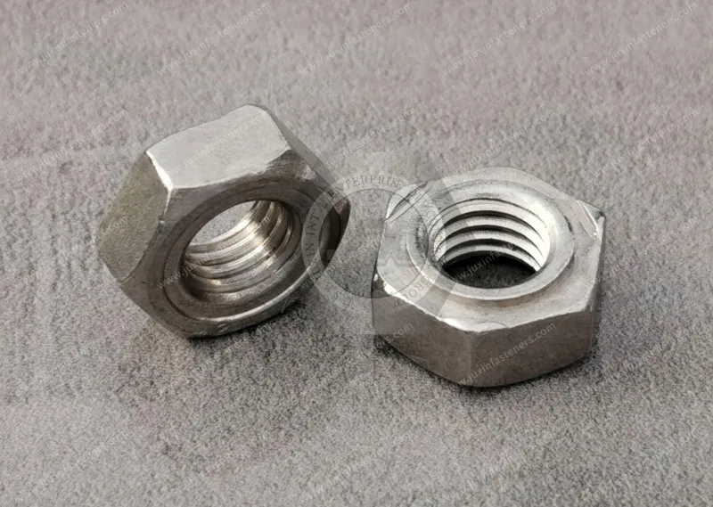
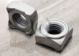
square weld nuts;
hex weld nuts;
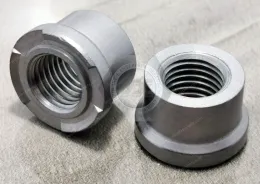
flanged weld nuts;
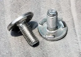
tab weld nuts;
custom weld nuts.
Geometry should be selected according to:
anti-rotation requirements;
available installation space;
sheet geometry;
load path;
welding access;
assembly access;
feeding requirements.
No single weld nut geometry is universally superior.
Projection design should be compatible with:
electrode configuration;
parent sheet;
welding equipment;
required weld area;
process stability.
The goal is not simply to maximize projection size.
The goal is to establish a controlled welding process that produces repeatable joint performance.
Important design considerations include:
sheet thickness;
hole configuration;
local stiffness;
edge distance;
nearby openings;
bends;
ribs;
reinforcement features;
electrode access.
Edge-distance requirements should be established from the actual weld process and component geometry rather than applying an arbitrary universal ratio.
If the weld nut is installed into a structural bracket, the engineer should evaluate:
Bolt
 ↓
Thread
 ↓
Weld Nut
 ↓
Weld Interface
 ↓
Parent Sheet
 ↓
Bracket / Structure
The weakest component controls the actual system performance.
This is why increasing the nominal strength of the weld nut may not improve the complete joint if the sheet, weld interface, or surrounding structure remains the limiting factor.
Squeeze time allows the electrodes to establish the intended mechanical contact before the welding current is applied.
Insufficient or inconsistent squeeze conditions can affect process repeatability.
Weld current influences heat generation through the resistance-welding process.
However, higher current is not automatically better.
Excessive welding energy can contribute to:
expulsion;
excessive indentation;
electrode contamination;
sheet damage;
undesirable thermal effects.
Weld time interacts with current, resistance, material, and electrode force.
A suitable weld schedule should be established through process development and validation rather than copied from a generic table.
Hold conditions allow the welded area to remain under electrode force after current interruption.
The appropriate process conditions depend on the welding system and materials.
Electrode force affects:
electrical contact;
projection collapse;
current distribution;
nugget development;
sheet deformation.
The required force must therefore be established for the actual fastener, substrate, and equipment.
Weld nut spin-out prevention matters wherever threaded attachment points are created through resistance welding.
Applications can include:
brackets;
structural mounting points;
underbody components;
shields;
support structures;
powertrain-related assemblies.
These applications may experience vibration, thermal cycling, and repeated assembly loads.
The actual design requirements depend on the vehicle architecture and customer specification.
BIW applications can include:
body brackets;
reinforcement structures;
seat-related components;
door and closure structures;
mounting points.
Automated welding and high production volumes make process consistency particularly important.
Safety-related applications require application-specific engineering validation and customer requirements.
Heavy equipment can include:
excavators;
agricultural machinery;
construction equipment;
industrial vehicles;
structural machinery.
These applications may experience:
vibration;
shock;
structural movement;
environmental exposure;
repeated maintenance.
The appropriate weld nut configuration should be determined from the actual load path and joint design.
Weld nuts may be used for:
internal mounting;
brackets;
control components;
cable-management hardware;
equipment supports.
Where a fastener participates in electrical bonding or grounding, the complete electrical interface must be evaluated separately from mechanical torque-out performance.
Weld nut quality is most effectively controlled when the fastener supplier, welding engineer, manufacturing engineer, and procurement team share the relevant information.
A useful communication chain is:
Customer Engineering Requirement
              ↓
Fastener Supplier DFM Review
              ↓
Fastener Geometry + Material
              ↓
Welding Process Development
              ↓
Prototype Validation
              ↓
Production Process Qualification
              ↓
Mass Production Control
              ↓
Ongoing Quality Monitoring
This approach is more reliable than discovering weld nut spin failure only after production assembly begins.
Depending on the customer and application, the quality package may include:
material certificates;
dimensional inspection records;
first article inspection;
weld validation results;
mechanical test results;
coating documentation;
process-control records;
lot traceability;
nonconformance records;
corrective-action documentation;
PPAP documentation where specifically required.
The documentation should correspond to actual customer requirements.
A supplier should not claim that one generic certificate proves all aspects of weld fastener performance.
| Failure Symptom | Potential Cause | Investigation Direction |
|---|---|---|
| Nut rotates during tightening | Weak weld interface | Examine weld area and process history |
| Thread strips before nut rotates | Insufficient thread capacity or incorrect thread condition | Check thread specification and material |
| One side of weld appears weaker | Uneven current or force distribution | Check electrode alignment and projection condition |
| Inconsistent production results | Process variation | Review welding parameters and equipment condition |
| Excessive indentation | Excessive localized welding/mechanical conditions | Review electrode force, current, and geometry |
| Weld expulsion | Excessive or unstable heat generation | Review current, contact, force, and surface condition |
| Sheet deforms around nut | Insufficient local stiffness or excessive process input | Review sheet geometry and welding conditions |
| Failure after coating change | Surface condition changed | Review coating, welding sequence, and contact condition |
| Failure occurs only at certain locations | Local geometry or current path issue | Review edge distance, nearby openings, and shunting |
| Failure appears after equipment maintenance | Process setup changed | Compare equipment and fixture conditions |
This matrix should be treated as a diagnostic framework rather than a universal failure-cause table.
Correct weld nut geometry selected
Material specified
Thread specification defined
Projection geometry controlled
Critical dimensions identified
Material identified
Sheet thickness identified
Hole geometry reviewed
Local stiffness evaluated
Edge and opening locations reviewed
Electrode access confirmed
Electrode alignment controlled
Electrode condition monitored
Welding process validated
Surface condition controlled
Fixture rigidity verified
Welding sequence reviewed
Torque-out requirement defined
Failure mode identified
Destructive testing performed where required
Weld interface examined
Production samples evaluated
Acceptance criteria documented
Material traceability defined
Dimensional inspection defined
Thread inspection defined
Projection inspection defined
Nonconformance process established
Change-control process established
Before approving a supplier, procurement and supplier-quality teams should ask:
Can the supplier review the weld nut drawing for manufacturability?
Can the supplier identify projection-related manufacturing risks?
How are critical dimensions controlled?
How are weld projections inspected?
How is raw material traced?
How are surface treatments controlled?
What testing can be supported during prototype validation?
Can the supplier provide dimensional and material documentation?
How are production changes controlled?
How are nonconforming lots contained?
Can the supplier support production-volume requirements?
Can the supplier provide technical support when weld performance problems occur?
These questions move supplier evaluation beyond unit price and toward actual manufacturing capability.
A strong RFQ should include more than the weld nut part number.
Provide, where applicable:
2D drawing;
3D CAD model;
material;
thread;
dimensions;
projection geometry;
surface finish;
special requirements.
parent sheet material;
sheet thickness;
welding method;
electrode configuration;
installation torque;
load direction;
environmental conditions;
assembly sequence.
torque-out test;
push-out test;
tensile test;
corrosion test;
dimensional inspection;
first article requirements;
PPAP requirements where applicable.
annual usage;
prototype quantity;
production quantity;
launch timing;
packaging requirements;
delivery location.
The more complete the RFQ, the more meaningful the supplier quotation and DFM feedback can become.
A common response to weld nut spin failure is:
“Use a larger weld nut.”
That may work in some applications, but it is not automatically the best engineering solution.
A larger fastener may introduce:
increased envelope;
larger hole requirements;
additional material;
greater assembly clearance requirements;
changes to welding tooling;
higher cost;
feeder changes.
Before changing fastener size, engineers should investigate whether the actual problem is:
projection geometry;
welding process;
electrode alignment;
surface condition;
substrate stiffness;
installation torque;
thread capacity;
joint load path.
The objective should be to correct the actual limiting mechanism.
A useful corrective-action sequence is:
1. Identify the failure mode
          ↓
2. Determine the weakest joint component
          ↓
3. Separate fastener failure from weld failure
          ↓
4. Review substrate and geometry
          ↓
5. Review welding process
          ↓
6. Review surface condition
          ↓
7. Validate corrective action
          ↓
8. Confirm production repeatability
          ↓
9. Establish ongoing process controls
This avoids changing multiple variables simultaneously without understanding which change actually solved the problem.
For procurement teams, weld nut spin failure is not only an engineering problem.
It can become a supply-chain problem when:
defective lots are quarantined;
production stops;
emergency replacement quantities are required;
alternative suppliers must be qualified;
tooling must be modified;
engineering drawings must be revised;
customer approval is required.
Therefore, supplier qualification should consider the supplier's ability to investigate and correct technical failures quickly and systematically.
A technically capable supplier can reduce the risk that a small fastener problem becomes a larger production disruption.
JUXIN FASTENERS supplies engineered fastening components for OEM and industrial applications, including:
weld nuts;
weld studs;
self-clinching nuts;
self-clinching studs;
blind rivet nuts;
threaded inserts;
custom threaded inserts;
CNC-machined fasteners;
custom screws and bolts;
stainless steel fasteners;
high-strength fastening components.
For weld nut applications, early engineering discussion can cover:
fastener geometry;
projection design;
material selection;
parent sheet compatibility;
welding process;
DFM;
dimensional requirements;
surface treatment;
prototype requirements;
torque-out or other application-specific validation;
production sourcing.
The objective is not to promise that one fastener will eliminate every possible joint failure.
The objective is to identify the actual engineering requirements and establish a fastener and manufacturing route that can be validated against them.
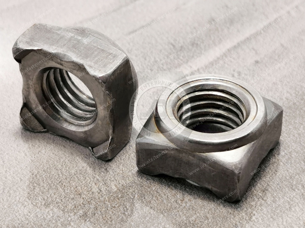
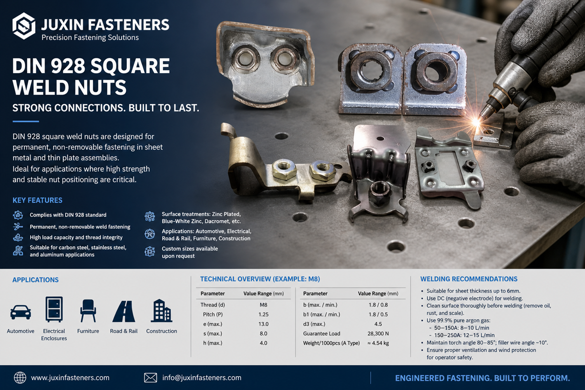
Useful for engineers evaluating square weld nut geometry, dimensional requirements, material, projection welding, and OEM applications.
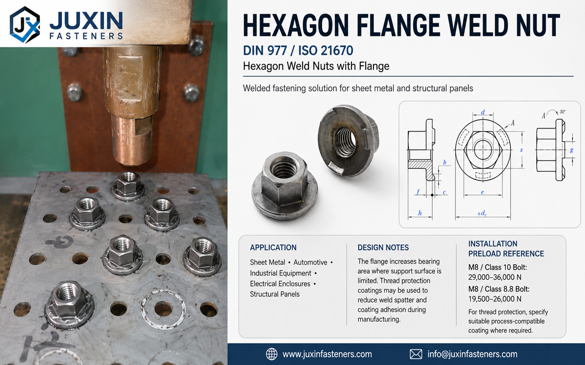
Relevant when flange geometry, load distribution, thread protection, and application-specific weld nut selection are being evaluated.
Relevant for non-standard weld nut geometries, custom projections, special mounting requirements, restricted installation envelopes, and OEM development programs.
Useful when engineers need to compare resistance-welded fastening with mechanically installed self-clinching solutions.
Relevant when access conditions, installation method, structural requirements, and production process need to be compared.
Useful for procurement and supplier-quality teams evaluating material traceability, dimensional inspection, process control, documentation, and change management.
Relevant when sourcing teams are preparing technical RFQs, evaluating suppliers, comparing quotations, and establishing long-term OEM supply programs.
Potential causes include inadequate weld-interface strength, incomplete projection collapse, uneven nugget formation, electrode misalignment, surface contamination, inappropriate welding conditions, substrate deformation, or installation torque exceeding the validated joint capability.
The actual root cause should be established through failure analysis rather than assumed from the symptom alone.
Torque-out failure occurs when a weld nut rotates relative to the parent sheet under an applied rotational load.
The failure may occur at the weld interface, but other mechanisms such as thread stripping or parent-sheet failure should be distinguished during testing.
No.
Increasing current can change heat generation, but excessive welding energy can also create undesirable effects such as expulsion, indentation, electrode contamination, or sheet damage.
The welding schedule must be developed for the actual fastener, substrate, equipment, and application.
No.
Fastener size, geometry, projection design, material, substrate, welding process, and joint load path all influence performance.
A larger fastener may help in some applications but can also introduce new dimensional and manufacturing constraints.
Use an application-appropriate torque-out test method with defined specimen configuration, installation conditions, loading method, and acceptance criteria.
The required torque-out value should come from the applicable engineering requirement or customer specification rather than a universal number.
Yes.
Thread strength and weld-interface strength are separate failure mechanisms.
A thread can remain intact while the weld attachment fails under rotational load.
Yes.
The parent sheet may deform, tear, or fail around the weld region if it is the weakest part of the joint.
The complete load path must therefore be considered.
Useful information includes the weld nut drawing, fastener material, parent sheet material and thickness, welding process, electrode configuration, welding conditions, installation torque, failed samples or test results, surface treatment, and production history.
Not necessarily.
PPAP requirements depend on the customer program and applicable quality agreement. Where PPAP is required, the required submission level and contents should be specified by the customer.
Yes. Custom weld nut projects can be evaluated based on the customer's drawings, CAD data, substrate, welding process, application requirements, annual volume, and validation requirements.
If your team is experiencing weld nut rotation, torque-out failure, inconsistent projection welding, or repeated weld fastener defects, provide the engineering information available for review.
Useful information includes:
2D engineering drawings;
3D CAD files;
weld nut part number;
material specification;
parent sheet material;
sheet thickness;
welding method;
electrode information;
installation torque;
required torque-out performance;
surface treatment;
annual production volume;
existing test or failure-analysis results.
Email: info@juxinfasteners.com
JUXIN FASTENERS can work with OEM engineering, procurement, manufacturing, and supplier-quality teams to evaluate weld fastener requirements,
DFM considerations, material and geometry options, prototype needs, and production sourcing.
Precision Fastening Solutions Since 2003.
For weld nut spin-out prevention, the correct engineering equation is not simply:
“Increase the weld.”
It is:
Fastener Geometry + Projection Design + Material + Parent Sheet + Surface Condition + Welding Process + Fixture + Assembly Torque + Load Path + Validation + Production Quality Control
That system-level approach provides a more reliable foundation for OEM weld fastener design, sourcing, and long-term production.
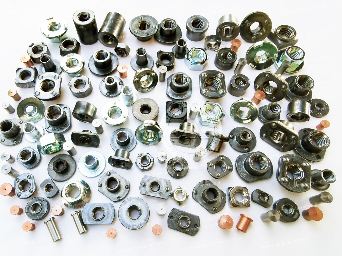
Product Packaging
Packaging Standard
At Juxin Fasteners, we apply standardized export packaging to ensure product protection, traceability, and compliance with international logistics requirements.
1. Standard Export Packaging
Unless otherwise specified, all products will be packed according to our factory standard export packaging, which includes:
Moisture-resistant inner protection
Poly bag or small box packing as required
Reinforced export cartons
Clear labeling with part number, specification, batch number, and quantity
Palletizing for sea or air shipment when necessary
Our standard packaging is designed to ensure safe transportation, efficient warehousing, and long-distance international shipping.
2. Customized Packaging Options
We also provide customized packaging solutions according to customer requirements, including but not limited to:
Private labeling
Customized barcodes
Specific carton dimensions
Retail packaging
Special pallet configuration
Customer-specific marking and identification
So that you know, customized packaging may involve additional costs and extended lead time depending on the complexity of the requirements.
3. Compliance & Quality Assurance
All packaging processes are controlled under our ISO 9001 quality management system to ensure consistency, traceability, and product integrity throughout the supply chain.
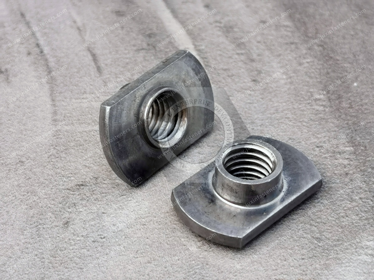
Product Pictures
Contact Us
Tel.:
+86 020 8621 0320
+86 020 3121 6067
E-mail:
Technical Support:
Navigation
SEND INQUIREY