Call Us
+86 136 6007 9809
Call Us
+86 136 6007 9809

What causes a weld nut to spin during final bolt installation?
A weld nut spin failure occurs when the weld joint between the nut and the sheet metal cannot withstand the rotational load generated during bolt installation or service.
Instead of the bolt tightening while the nut remains securely fixed, the nut rotates relative to the parent sheet.
Product Specification
What causes a weld nut to spin during final bolt installation?
A weld nut spin failure occurs when the weld joint between the nut and the sheet metal cannot withstand the rotational load generated during bolt installation or service.
Instead of the bolt tightening while the nut remains securely fixed, the nut rotates relative to the parent sheet.
The failure may originate from insufficient weld nugget development, inconsistent projection collapse, electrode misalignment, unsuitable welding parameters,
contamination at the weld interface, poor fit-up, excessive installation torque, or a mismatch between the fastener design and the sheet material.
It is important to distinguish weld-joint failure from parent-sheet failure.
A weld nut does not automatically have unlimited torque-out resistance simply because it is projection welded.
The actual resistance of the assembly depends on the weld nut geometry, projection design, fastener material, sheet material and thickness, weld process, joint configuration, and specified performance requirements.
A simplified failure mechanism can be represented as follows:
              [ Applied Bolt Torque ]
                        |
                        v
              +-------------------+
              |     WELD NUT      |
              +-------------------+
                 Weld Interface
              [ Nugget / Fusion Zone ]
=============================================
              Base Sheet Metal
When the weld interface provides sufficient resistance, the nut remains fixed while the bolt is tightened.
When the weld joint is undersized, incomplete, asymmetric, contaminated, or otherwise defective, the applied torque can exceed the rotational capacity of the joint and cause the nut to rotate.
For high-volume OEM production, weld nut spin prevention therefore requires more than selecting a nominal fastener size.
It requires coordination between weld nut projection geometry, sheet-metal design, welding parameters, electrode condition, surface condition, process validation, and torque requirements.
JUXIN FASTENERS supplies weld nuts and other industrial fastening components for OEM applications where the fastener must be evaluated together with the material, assembly process, and required joint performance.
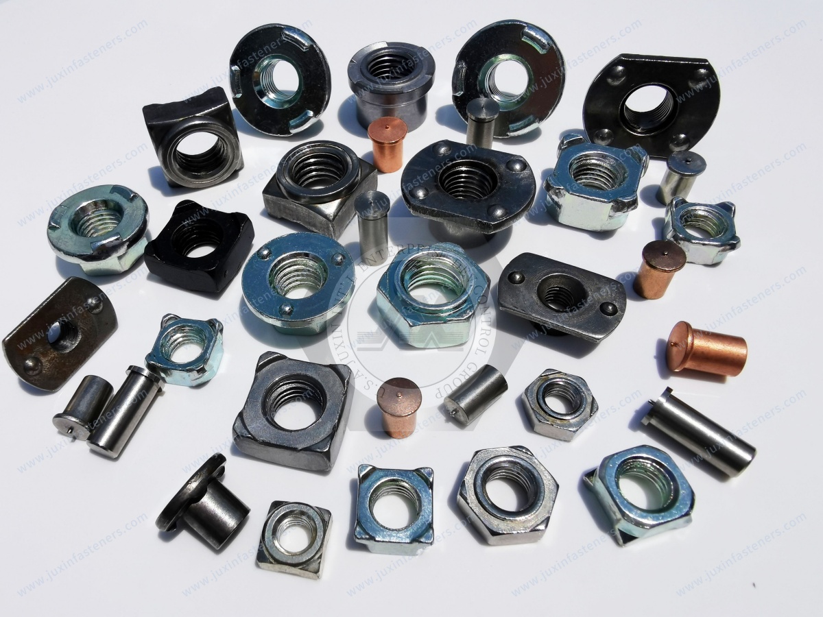
Weld nut spin failure is usually a system-level assembly problem rather than a single-dimensional fastener problem.
The following failure mechanisms should be investigated during engineering validation and production troubleshooting.
Projection welding relies on controlled contact between the projections on the weld nut and the parent sheet.
Electrical resistance generates localized heat, while electrode force controls contact and projection collapse.
If the welding current, weld time, electrode force, or other process conditions are unsuitable for the specific material combination, the projections may not develop the intended weld joint.
This can result in:
Incomplete projection collapse
Insufficient fusion or nugget development
Non-uniform weld areas
Localized bonding instead of a sufficiently developed joint
Reduced resistance to rotational loading
During final bolt installation, the torque is transferred from the internal thread into the nut body and then through the weld joint into the sheet.
If the weld interface is weaker than the applied rotational load, the nut can rotate.
The correct engineering approach is therefore not simply to increase welding current.
Welding parameters must be developed as a coordinated process window based on the actual fastener, sheet material, thickness, surface condition, electrode configuration, and welding equipment.
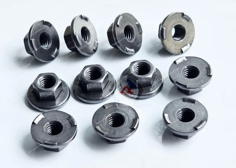
Projection weld nuts typically contain multiple projections. For reliable welding, the projections should engage the sheet in a controlled and repeatable manner.
Electrode alignment and seating are therefore important process variables.
If the electrode faces are not properly aligned, or if the weld nut and sheet are not correctly seated, the load and electrical current distribution may become uneven.
One projection may collapse differently from another, producing an asymmetric weld pattern.
Potential consequences include:
Uneven projection collapse
Inconsistent current distribution
Localized overheating
Incomplete development of individual weld areas
Reduced overall joint consistency
Increased variation in torque-out performance
Rather than relying on a universal dimensional tolerance for electrode parallelism,
production teams should establish alignment requirements appropriate to the specific welding machine, electrode geometry, weld nut design, and application.
Regular inspection of electrode condition and alignment should be incorporated into the welding process-control plan.
The condition of the sheet and weld nut surface can have a major influence on resistance welding behavior.
Possible sources of variation include:
Excessive oil or lubricant
Mill scale
Oxide layers
Surface coatings
Dirt or foreign material
Excessive or unsuitable plating at the weld interface
Inconsistent material surface condition
These conditions can change electrical contact resistance and alter the way heat develops during the welding pulse.
The result may be excessive localized heating, expulsion, unstable nugget formation, inconsistent projection collapse, or insufficient weld development.
However, surface coatings should not automatically be classified as "unweldable." Weldability depends on the specific coating,
coating thickness, base material, welding process, and process parameters. The correct approach is to validate the actual material and surface condition rather than apply a universal rule.
A weld nut can also experience rotation because the assembly torque exceeds the validated torque-out capability of the weld joint.
This distinction is important.
A properly welded nut may still fail if:
The specified bolt installation torque is too high
The fastener thread specification is incorrect
Lubrication changes thread friction
A power tool produces excessive peak torque
Thread locking compounds alter the torque relationship
Cross-threading or thread damage creates abnormal resistance
The application uses a tightening condition different from the original validation condition
For this reason, weld nut torque-out validation should be evaluated together with the actual bolt, nut thread, lubrication condition, tightening method, and required installation torque.
Weld nut performance is also influenced by the relationship between the fastener and the parent sheet.
Important variables include:
Fastener material
Fastener geometry
Projection geometry
Sheet material
Sheet thickness
Surface condition
Joint accessibility
Welding equipment
Electrode configuration
Required torque
Required service loads
A weld nut designed for one sheet-metal condition should not automatically be assumed to provide identical performance when transferred to a substantially different material or thickness.
This is particularly important when OEM programs move from conventional low-carbon steel to coated steel, stainless steel, high-strength steel, aluminum, or other engineered substrates.
Preventing weld nut spin failure begins before production. The fastener, sheet, welding process, and final tightening operation should be treated as one integrated joint.
The fundamental relationship between welding current, resistance, and time is commonly represented by:
Heat input ∝ I²Rt
where current, resistance, and time interact to determine the thermal energy generated at the weld interface.
The practical objective is not to maximize heat input. It is to establish a stable process window that provides appropriate projection collapse and weld
development without causing excessive expulsion, electrode sticking, sheet damage, or unnecessary heat input.
Parameter development should consider:
Welding current
Weld time
Electrode force
Squeeze time
Hold time
Electrode geometry
Fastener projection geometry
Sheet material
Sheet thickness
Surface condition
Welding machine characteristics
Production validation should be based on actual process trials rather than generic parameter values.
Electrode condition directly affects current delivery and mechanical loading.
Production teams should monitor:
Electrode wear
Electrode contamination
Electrode dressing condition
Electrode alignment
Electrode contact area
Mechanical seating of the fastener
Repeatability of the welding fixture
If the electrode becomes worn or contaminated, the effective welding conditions can change even when the programmed machine settings remain unchanged.
This is one reason why a weld process that passes initial validation can later develop torque-out or spin failures during production.
Projection geometry is a critical part of the weld interface.
For multi-projection weld nuts, the projections should provide repeatable contact and predictable collapse under the selected welding conditions.
Important manufacturing characteristics may include:
Projection height
Projection shape
Projection location
Nut flatness
Thread position
Fastener material
Dimensional consistency
The actual acceptable tolerance should be established according to the specific weld nut design and application rather than applying an unsupported universal value.
JUXIN FASTENERS can work with OEM customers on fastener drawings and application requirements to evaluate projection geometry, material, dimensional consistency, and production requirements.
Before welding, the production process should define acceptable surface conditions for both the fastener and parent sheet.
Where coatings, oils, or plated surfaces are involved, the engineering team should verify their effect through process testing.
The objective is to achieve repeatable electrical contact and thermal behavior across production batches.
For high-volume OEM applications, the control plan may include:
Incoming material inspection
Surface-condition verification
Fastener dimensional inspection
Weld parameter monitoring
Electrode maintenance
Destructive weld testing
Torque-out testing
Periodic metallographic examination
Torque-out testing should reproduce the actual assembly conditions as closely as practical.
The validation should consider:
The actual weld nut specification
The actual sheet material and thickness
The actual welding process
The actual bolt specification
The actual tightening method
The actual lubrication or coating condition
The required installation torque
The expected service environment
The purpose is not simply to obtain a single high torque number.
The objective is to demonstrate that the weld joint provides adequate rotational resistance with an appropriate margin for the intended assembly and service conditions.
When a weld nut fails torque-out testing, the failure surface should be examined rather than recording only the torque value.
Useful observations include:
Whether the weld interface separated
Whether the parent sheet tore
Whether individual projections failed differently
Whether the weld area is symmetric
Whether visible porosity or voids are present
Whether expulsion occurred
Whether the sheet itself was damaged
Whether the failure occurred at the weld interface or elsewhere in the assembly
This information can distinguish a welding-process problem from a fastener-design problem, sheet-metal problem, or assembly-torque problem.
When an OEM production line experiences weld nut rotation, the investigation should proceed systematically.
Determine whether the nut is actually rotating relative to the sheet.
Do not assume that every torque failure is a weld failure. Possible alternative failure modes include:
Bolt thread stripping
Nut thread damage
Parent-sheet deformation
Fastener deformation
Tool over-torque
Cross-threading
Incorrect fastener specification
Examine the weld area for:
Incomplete projection collapse
Uneven weld development
Expulsion
Surface burning
Cracking
Evidence of contamination
Inconsistent projection engagement
Compare actual production conditions with validated settings.
Review:
Current
Weld time
Electrode force
Squeeze time
Hold time
Machine repeatability
Electrode condition
Parameter drift can be particularly important when the failure appears intermittently rather than continuously.
Inspect the weld nuts for dimensional consistency.
Pay particular attention to:
Projection dimensions
Nut flatness
Projection location
Thread dimensions
Overall fastener geometry
Material condition
Confirm:
Material grade
Thickness
Surface coating
Surface cleanliness
Material lot variation
Forming condition around the weld location
A change in sheet material or coating can alter the welding behavior even when the fastener and machine settings remain unchanged.
Produce sample assemblies using controlled fasteners, controlled sheet material, and validated welding equipment.
Then compare:
Good Assembly → Torque-Out Test → Failure Mode
against
Production Failure → Torque-Out Test → Failure Mode
This comparison can help isolate whether the root cause is related to the fastener, process, material, or assembly operation.
A robust weld nut quality program should combine process controls with mechanical testing.
Visual inspection can identify obvious problems such as:
Misaligned weld nuts
Incomplete seating
Excessive weld spatter
Surface burning
Projection collapse abnormalities
Fastener displacement
Visual inspection is useful but should not be treated as sufficient proof of weld strength.
Torque-out testing directly evaluates the ability of the welded nut to resist rotational loading.
The test method should define:
Test specimen configuration
Bolt specification
Tightening condition
Test equipment
Torque measurement method
Failure criterion
Sampling frequency
Acceptance criteria should be based on the application's actual engineering requirements or the applicable customer specification.
Depending on the weld nut design and application, axial destructive testing can be used to evaluate the joint's resistance to separation.
The failure mode should be recorded, not simply the peak load.
A parent-sheet failure, weld-interface failure, or fastener deformation can provide different information about joint behavior.
Periodic cross-sectional examination can provide additional information about weld development.
It may reveal:
Nugget development
Fusion characteristics
Projection collapse
Voids or discontinuities
Heat-affected regions
Asymmetry between multiple weld locations
Metallography is particularly useful when mechanical test results indicate inconsistent performance and the engineering team needs to identify the underlying weld-interface condition.
For procurement teams, weld nut quality should not be evaluated only by unit price.
A lower-cost weld nut that produces inconsistent projection geometry can create additional costs through:
Production downtime
Welding parameter adjustment
Increased inspection
Assembly defects
Rework
Field failures
Customer complaints
Line-side sorting
A technically suitable OEM weld nut supplier should therefore be able to discuss more than the nominal thread size.
RFQ and supplier evaluation should consider:
Fastener material
Thread specification
Nut geometry
Projection design
Sheet material
Sheet thickness
Surface condition
Welding process
Required installation torque
Required mechanical performance
Inspection requirements
Production volume
Packaging and traceability requirements
For custom or application-specific weld nuts, providing the supplier with the sheet material, thickness, drawing,
welding process, and expected torque requirement can significantly improve engineering evaluation.
One of the most important lessons in weld nut failure analysis is that the fastener and welding process cannot be evaluated independently.
A weld nut may perform correctly in one production environment and poorly in another because the actual joint is different.
The following framework can help:
If projection geometry is inconsistent:
Investigate fastener manufacturing and incoming quality.
If weld development is inconsistent:
Investigate welding parameters, electrode condition, alignment, and surface condition.
If the weld is consistent but torque-out is insufficient:
Review weld nut design, sheet material, joint geometry, and application torque requirements.
If torque-out failures occur only during production assembly:
Investigate tightening equipment, torque settings, lubrication, thread condition, and assembly method.
If failures occur after material or coating changes:
Revalidate the welding process for the new substrate condition.
This approach avoids the common mistake of immediately changing the fastener when the actual root cause is process variation.
Weld Fasteners Solutions: JUXIN FASTENERS Weld Fasteners Solutions
Projection Welding Engineering: Projection Welding Process & DFM Joint Optimization
Product Category: JUXIN FASTENERS Projection Weld Nuts
Engineering Comparison: Weld Nuts vs. Self-Clinching Nuts
Engineering Comparison: Weld Nuts vs. Blind Rivet Nuts
Engineering Support: Weld Fastener Failure Analysis and OEM Application Evaluation
Conduct controlled destructive torque-out testing on representative welded assemblies using the actual weld nut, sheet material, welding process, and intended assembly conditions.
After testing, inspect the failure interface rather than recording only the peak torque. Determine whether failure occurred at the weld interface, through the parent sheet, within the fastener, or elsewhere in the assembly.
This failure-mode information is often more valuable than a single torque number because it helps identify the actual limiting component of the joint.
A surface coating can affect resistance welding behavior, but the effect depends on the coating type, coating thickness, base material, interface condition, and welding process.
Some coated materials can be resistance welded successfully when the process is specifically developed for that material combination.
Therefore, it is not technically correct to assume that all zinc-coated surfaces automatically cause weld nut spin failure.
Where a coating change is introduced, the welding process and joint performance should be revalidated.
A visually acceptable weld does not necessarily prove adequate rotational strength.
The weld may have:
Insufficient effective weld area
Uneven nugget development
Internal discontinuities
Localized bonding
Inadequate mechanical engagement
Excessive assembly torque
For critical applications, mechanical testing should supplement visual inspection.
No.
Increasing current may improve weld development under some conditions, but excessive current can also cause expulsion, surface damage, electrode problems, or undesirable heat input.
The correct objective is to establish a suitable process window for the specific fastener, sheet material, thickness, electrode configuration, and welding equipment.
For an engineering-level RFQ, useful information includes the weld nut drawing or thread specification, sheet material and thickness, surface treatment, welding method, installation torque, expected service conditions, annual volume, and any customer-specific quality requirements.
Providing this information allows the supplier to evaluate the complete fastening joint rather than quoting only a nominal nut size.
If your production line is experiencing weld nut rotation, inconsistent torque-out performance, weld spatter, projection collapse variation,
or other resistance-welding problems, the root cause may involve the interaction between the fastener, sheet metal, welding process, and assembly conditions.
JUXIN FASTENERS can support OEM customers in evaluating weld nut specifications, projection geometry, material selection, application conditions, and sourcing requirements.
For technical evaluation, provide:
Weld nut drawing or specification
Sheet material and thickness
Surface treatment or coating
Welding process and equipment information
Required bolt size and installation torque
Application drawings or assembly details
Production volume
Existing failure samples or test results
Email: info@juxinfasteners.com
JUXIN FASTENERS provides OEM weld fasteners and application-oriented engineering support for manufacturers requiring reliable threaded fastening in sheet-metal assemblies.
The objective is not simply to supply a weld nut. It is to help establish a fastening system in which fastener geometry, weld process, parent material, mechanical requirements,
and production conditions work together consistently.
Product Packaging
Packaging Standard
At Juxin Fasteners, we apply standardized export packaging to ensure product protection, traceability, and compliance with international logistics requirements.
1. Standard Export Packaging
Unless otherwise specified, all products will be packed according to our factory standard export packaging, which includes:
Moisture-resistant inner protection
Poly bag or small box packing as required
Reinforced export cartons
Clear labeling with part number, specification, batch number, and quantity
Palletizing for sea or air shipment when necessary
Our standard packaging is designed to ensure safe transportation, efficient warehousing, and long-distance international shipping.
2. Customized Packaging Options
We also provide customized packaging solutions according to customer requirements, including but not limited to:
Private labeling
Customized barcodes
Specific carton dimensions
Retail packaging
Special pallet configuration
Customer-specific marking and identification
So that you know, customized packaging may involve additional costs and extended lead time depending on the complexity of the requirements.
3. Compliance & Quality Assurance
All packaging processes are controlled under our ISO 9001 quality management system to ensure consistency, traceability, and product integrity throughout the supply chain.
Product Pictures
Contact Us
Tel.:
+86 020 8621 0320
+86 020 3121 6067
E-mail:
Technical Support:
Navigation
SEND INQUIREY