Call Us
+86 136 6007 9809
Call Us
+86 136 6007 9809

When a vehicle assembly requires a fastening component that cannot be adequately sourced from a standard catalog,
the engineering team may move from catalog selection to drawing-based development.
Product Specification
When a vehicle assembly requires a fastening component that cannot be adequately sourced from a standard catalog, the engineering team may move from catalog selection to drawing-based development.
Automotive fasteners made to drawing allow OEMs and Tier suppliers to define the required geometry, thread, material, tolerances,
surface finish and other functional characteristics through controlled engineering documentation.
For procurement and supplier development teams, drawing-based sourcing also creates a common technical reference between the customer and supplier.
Instead of describing a fastener only by a product name or photograph, the buyer can define the exact part that needs to be quoted and manufactured.
However, providing a drawing does not automatically make a component production-ready.
The drawing must communicate design intent clearly, the supplier must understand manufacturing feasibility, critical characteristics must be identified,
samples must be evaluated where required, and revisions must remain under control throughout development.
This guide explains the complete process for sourcing automotive fasteners made to drawing, from engineering design and technical review through prototype development, validation and production.
Automotive fasteners made to drawing are custom or non-standard fastening components manufactured according to customer-supplied engineering documentation.
The documentation may include:
2D technical drawings
3D CAD models
Material specifications
Surface treatment specifications
Customer standards
Applicable international standards
Functional requirements
Inspection requirements
Physical samples
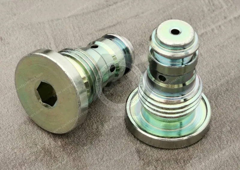
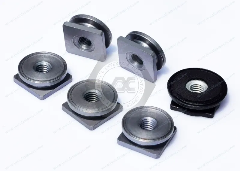
The final component may be a custom screw, bolt, nut, washer, self-clinching fastener, weld nut, weld stud, rivet nut, clip, retainer or another fastening component.
The important point is that “made to drawing” describes the sourcing and engineering method, not a single product type.
A standard fastener can sometimes be purchased directly from a published specification. A custom fastener, by contrast, normally requires a controlled technical definition before production.
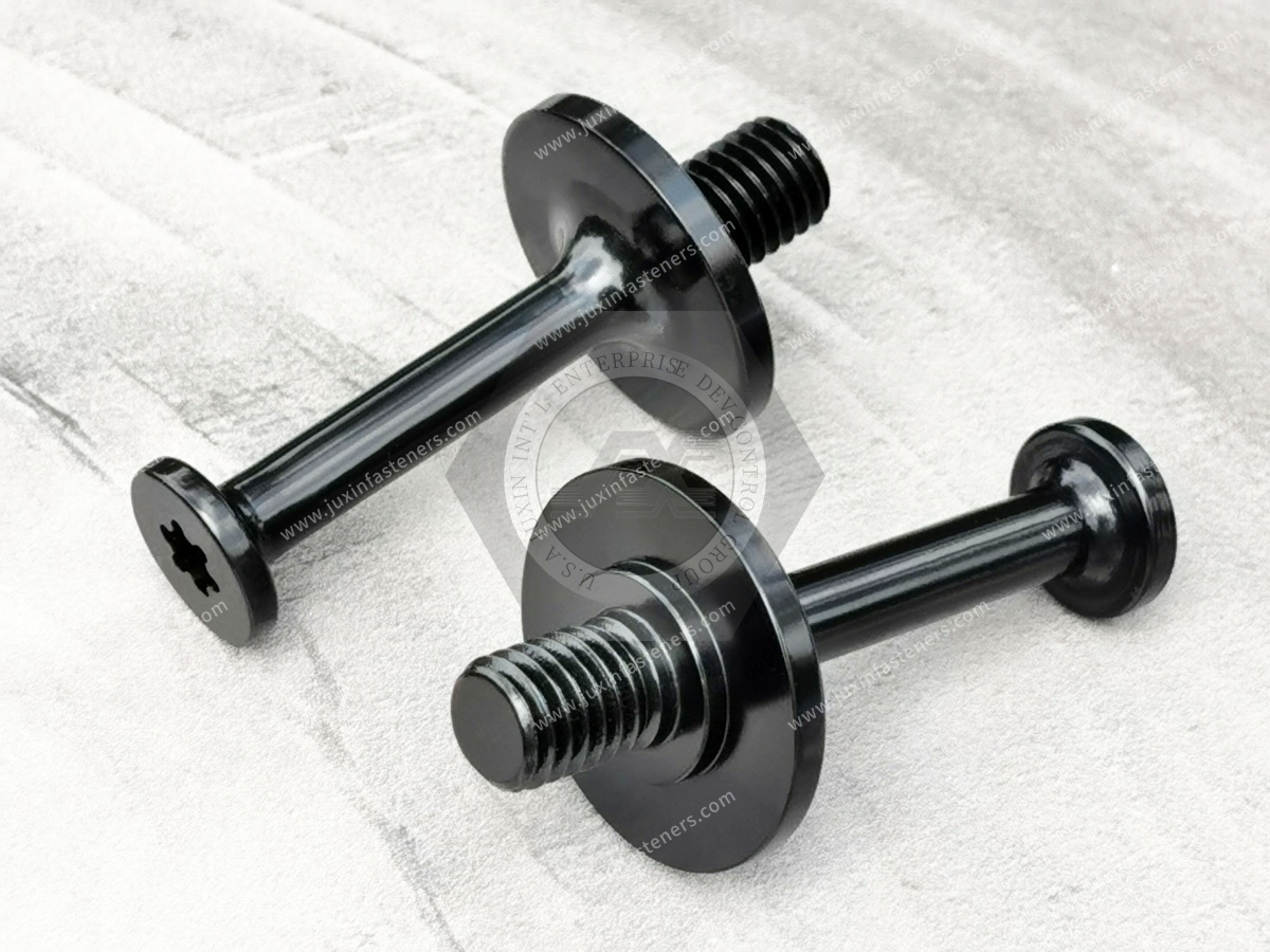
Automotive assemblies often contain constraints that cannot be fully described by a generic product name.
For example, an engineering team may need a fastener with:
A specific head diameter
A non-standard head height
A defined thread length
A particular thread specification
A controlled under-head radius
A special flange
A specific washer geometry
A particular material or property class
A defined surface finish
Restricted installation clearance
A customer-specific dimensional tolerance
A drawing-based specification converts these requirements into measurable characteristics.
This creates an important connection between engineering and procurement.
The drawing communicates:
Design intent
Functional dimensions
Material requirements
Tolerances
Interface requirements
Critical characteristics
The same drawing establishes:
What part is being quoted
Which requirements are mandatory
Which characteristics require supplier confirmation
Which suppliers can technically manufacture the component
What should be compared between quotations
The drawing provides a technical baseline for:
Feasibility review
Sample development
Quality planning
Revision control
Production approval
This is why drawing-based sourcing is more than a manufacturing instruction. It is also a supplier communication and procurement control document.
A production-ready drawing should contain enough information for a qualified supplier to understand what must be manufactured and what must be controlled.
The exact requirements depend on the part, but a typical custom automotive fastener drawing may include the following.
The drawing should clearly identify:
Part number
Part name
Drawing number
Revision level
Applicable customer or project reference
Units of measurement
General drawing notes
Clear identification is particularly important when multiple revisions of a similar fastener are being developed.
The drawing should define the dimensions that control:
Assembly fit
Clearance
Bearing surfaces
Overall envelope
Thread engagement
Installation access
Interaction with mating components
Not every dimension necessarily has the same functional importance.
This leads to one of the most useful principles in custom fastener development:
Separate critical-to-function dimensions from dimensions that primarily support manufacturing definition.
A drawing with clearly identified critical characteristics is generally easier to quote, manufacture and inspect than a drawing where every dimension is treated as equally important.
Geometric Dimensioning and Tolerancing (GD&T) can be used where geometric relationships are important to assembly performance.
Depending on the component, this may include controls related to:
Position
Orientation
Profile
Runout
Concentricity or coaxial relationships where applicable
Datum references
GD&T should be applied according to the actual functional requirement.
Adding geometric tolerances without a clear functional reason can increase manufacturing and inspection complexity without providing meaningful assembly value.
Thread information should be explicit.
For metric fasteners, this may include:
Nominal diameter
Pitch
Thread form
Internal or external thread
Tolerance class
Thread length
Thread runout or end condition where relevant
For inch-based applications, the applicable ASME/ANSI or SAE thread specification should be clearly identified.
A drawing that simply states “M6” or “1/4 inch thread” may not contain enough information for production.
Thread definition should also be compatible with the mating component.
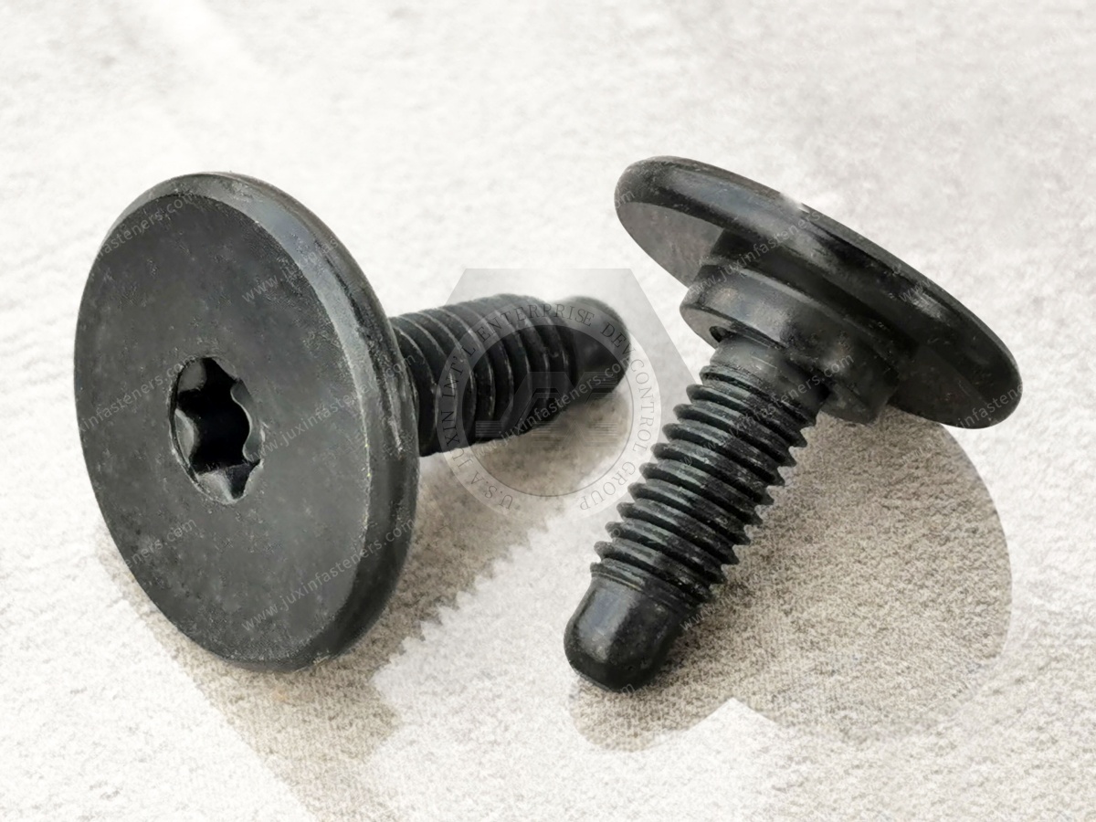
Material should be identified according to an applicable international, regional or customer specification.
Depending on the fastener, this may involve:
Carbon steel
Alloy steel
Stainless steel
Aluminum
Brass
Bronze
Other specified engineering materials
For steel fasteners, the drawing may also specify the applicable mechanical property class or mechanical requirements.
The supplier should not be expected to determine the material solely from the visual appearance of a sample.
Where applicable, the drawing may define:
Property class
Tensile requirements
Hardness
Case hardening requirements
Heat treatment condition
Other mechanical characteristics
For metric carbon and alloy steel fasteners, property classes such as 8.8, 10.9 and 12.9 may be relevant under applicable standards such as ISO 898-1.
The correct requirement depends on the fastener type and application.
A drawing should therefore specify the actual required standard or mechanical property rather than relying on a generic statement such as “high strength.”
Surface treatment should be defined separately from the base material.
Possible requirements may include:
Trivalent zinc systems
Zinc-nickel alloy systems
Black zinc finishes
Other customer-specified protective coatings or treatments
Where the joint is sensitive to friction, the relevant friction or torque-tension requirements should also be addressed in the specification.
Color alone should not be treated as a complete surface-finish specification.
A 3D CAD model and a 2D engineering drawing serve different purposes.
A STEP or IGES model can help communicate:
Overall geometry
Component interfaces
Spatial relationships
Assembly interference
Complex profiles
It is particularly useful during digital design and manufacturing feasibility review.
The 2D drawing normally communicates the controlled production requirements, including:
Dimensions
Tolerances
Threads
Material
Surface finish
Notes
Inspection requirements
Revision status
For many custom fastener projects, the strongest technical package is therefore:
3D CAD model + controlled 2D production drawing + applicable specifications
The 3D model helps communicate the shape.
The 2D drawing defines what must be controlled.
Before production begins, the supplier should review whether the specified geometry can be manufactured consistently.
This is where engineering design meets manufacturing reality.
Typical review points include:
The supplier may review:
Head diameter
Head height
Drive configuration
Corner geometry
Under-head transitions
Material flow requirements
Very long, thin or highly specialized geometries may require a different production approach from conventional fasteners.
The supplier should determine whether the component is suitable for forming, machining or a combination of processes.
The supplier may review:
Thread diameter
Thread length
Thread tolerance
Thread start
Runout
Forming or cutting requirements
Depending on geometry, some custom fasteners may require additional operations after the primary forming or machining process.
Potential processes can include:
Thread rolling
Thread cutting
CNC machining
Drilling
Slotting
Secondary forming
Heat treatment
Surface finishing
The final manufacturing route depends on the actual component design, material, volume and required tolerances.
A practical drawing-to-production workflow can be divided into several stages.
The supplier reviews:
2D drawing
3D CAD
Material specification
Surface finish
Functional requirements
Applicable standards
Quantity
Delivery requirements
The objective is to identify missing information before quotation or production.
The supplier evaluates whether the specified geometry, material and tolerances are practical for the intended production route.
Questions may include:
Can the head geometry be formed?
Is secondary machining required?
Can the specified thread be produced?
Are the tolerances appropriate for the manufacturing process?
Are there potential tool-access issues?
Is the material suitable for the intended process?
Once the technical requirements are sufficiently clear, the supplier can prepare a quotation covering relevant commercial factors such as:
Unit price
Tooling requirements
Prototype cost
Minimum order quantity
Production quantity
Lead time
Packaging
Shipping terms
This is where engineering and procurement requirements need to remain aligned.
Where required, initial samples are produced for dimensional, assembly and functional evaluation.
The exact prototype method depends on the component.
For example, low-volume samples may use a different manufacturing route from the eventual production process.
This distinction is important.
A prototype should prove the design, but the production process must also be capable of reproducing the approved design consistently.
The customer evaluates the sample against the engineering requirements.
Depending on the application, validation may include:
Dimensional inspection
Thread verification
Assembly fit
Installation testing
Material verification
Mechanical testing where specified
Surface finish verification
Functional testing defined by the customer
Not every fastener requires every test.
Testing should be linked to the drawing and application requirements.
Once the sample meets the applicable requirements, the customer can approve the design for production according to its internal release process.
The approved drawing revision becomes the manufacturing reference.
At this point, control of:
Part number
Drawing revision
Material
Process requirements
Inspection requirements
Packaging requirements
becomes particularly important.
Not every automotive sourcing project begins with a complete drawing.
There are two common starting points.
The customer provides:
2D drawing
3D CAD
Material specification
Surface treatment
Functional requirements
This is generally the clearest route when the engineering design is already established.
The customer provides:
Physical fastener sample
Existing component
Legacy part
Reference component
The supplier can then review the physical geometry and available information.
However, a physical sample cannot reliably reveal every engineering requirement.
It may not identify:
Exact material grade
Heat treatment condition
Internal stress requirements
Original thread tolerance
Coating specification
Required mechanical performance
Critical service conditions
Therefore, sample-based development should not assume that “measure the sample and copy everything” is equivalent to reproducing the original engineering specification.
Where possible, sample dimensions should be combined with application information and customer approval.
A sample can provide valuable information about the existing component.
Potentially measurable characteristics include:
Overall length
Head diameter
Head height
Thread diameter
Thread length
Washer dimensions
Flange dimensions
External profile
Drive geometry
However, some requirements require additional information or testing.
For example, visual inspection alone cannot reliably determine:
Exact steel grade
Property class
Heat treatment condition
Coating composition
Thread tolerance
Functional load requirements
This distinction is important for procurement teams replacing an obsolete or legacy fastener.
A physically similar component is not necessarily a technically equivalent replacement.
Quality control should be connected directly to the customer drawing and agreed specification.
Typical inspection categories can include:
Critical dimensions may include:
Overall length
Head dimensions
Diameter
Flange geometry
Washer dimensions
Threaded length
Other CTQ characteristics
Thread characteristics should be verified using methods appropriate to the specified thread system and tolerance.
For example, suitable thread gauges may be used for production verification where applicable.
Where specified, material composition and mechanical properties can be verified using appropriate testing methods.
Where the drawing specifies hardness, tensile properties or other mechanical requirements, the corresponding tests should be defined and performed according to the applicable specification.
Coating or surface treatment should be checked against the customer's specified requirements.
The important principle is:
Inspection should follow the engineering specification.
A supplier should not simply provide a generic list of tests without considering which characteristics actually control the part's function.
Revision control is one of the most important parts of drawing-based sourcing.
Automotive programs can undergo multiple engineering changes during development.
A change may affect:
Thread length
Overall length
Head geometry
Material
Surface finish
Tolerance
Packaging
Functional requirements
A supplier should manufacture against the correct approved revision.
Procurement teams should therefore maintain clear control of:
Drawing number
Revision level
Part number
Purchase order reference
Approved sample
Specification version
The supplier quotation should also identify any assumptions or technical clarifications that could affect the quoted part.
Without controlled revisions, several risks can occur:
Old tooling may be used
Obsolete drawings may be quoted
Samples may be compared against the wrong revision
Production lots may be mixed
Engineering changes may not reach all supply-chain participants
For this reason, drawing revision is not administrative paperwork.
It is part of the technical definition of the component.
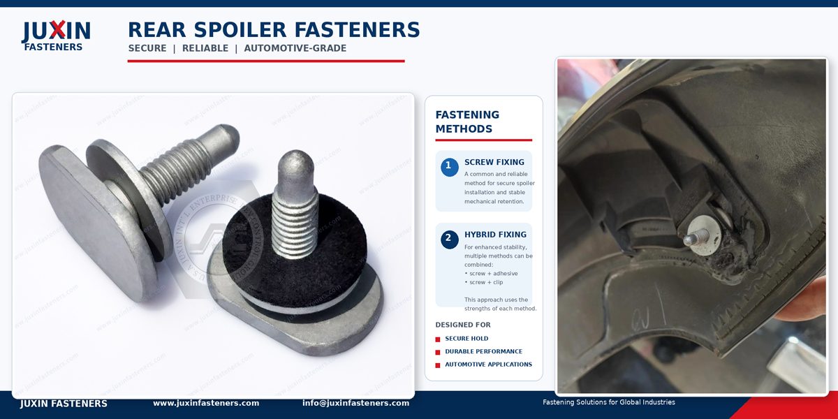
A custom fastener can be a small component, but a small dimensional change can affect the complete assembly.
For example, changing:
Thread length
Head height
Washer thickness
Flange diameter
Surface finish
Material
may affect assembly fit, clamp stack-up, tooling access or joint behavior.
When a drawing revision changes, the engineering team should determine whether the change requires:
New samples
New tooling
New inspection requirements
New validation
Customer approval
The supplier should not assume that a revision is “minor” simply because the fastener itself is small.
For purchasing and supply-chain teams, custom fasteners require more than comparing unit prices.
Important commercial considerations include:
Some custom geometries may require dedicated tooling.
The RFQ should clarify:
Whether tooling is required
Tooling cost
Tooling ownership where applicable
Expected tooling life where relevant
Tooling maintenance responsibility
Minimum order quantity can depend on:
Material purchasing
Production setup
Tooling
Process efficiency
Packaging
Supplier production economics
Procurement teams should therefore evaluate MOQ together with annual demand rather than treating MOQ as an isolated commercial number.
Estimated annual usage helps suppliers evaluate the appropriate production route.
A component ordered at several hundred pieces per year may have a different economic solution from a component ordered at hundreds of thousands of pieces per year.
Lead time may include:
Engineering review
Raw material procurement
Tooling
Prototype production
Customer approval
Production
Surface treatment
Packaging
For a new custom fastener, the first production cycle should therefore not be evaluated using the same assumptions as a repeat order.
For automotive supply chains, packaging should be defined according to the customer's logistics and handling requirements.
The RFQ or purchase specification may define:
Quantity per package
Box or container requirements
Part identification
Lot identification
Label information
Packaging orientation
Special separation requirements
The objective is to ensure that the correct fastener reaches the assembly process with clear identification.
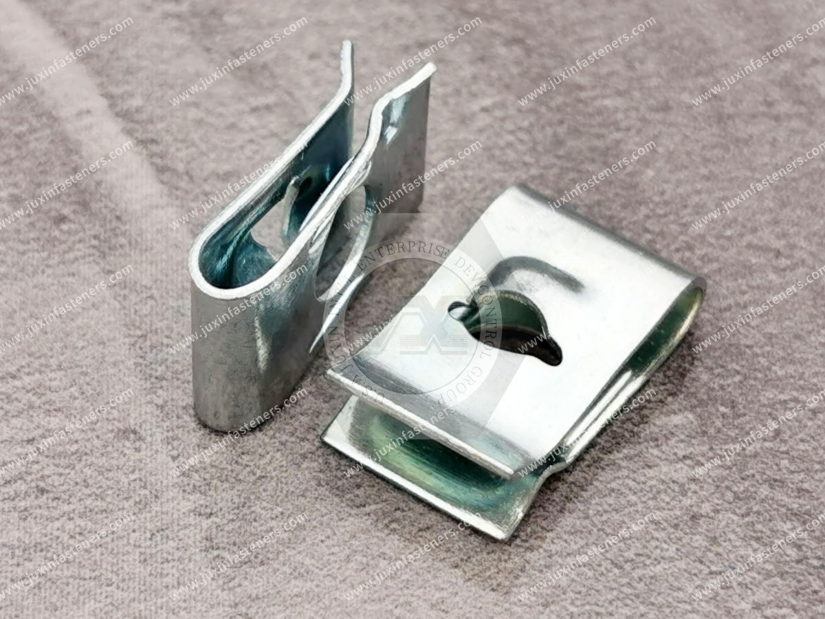
A strong RFQ allows a supplier to evaluate technical feasibility and commercial requirements at the same time.
Procurement teams should provide the following where available.
2D production drawing
3D CAD model
PDF specification
Applicable standards
Customer-specific requirements
Physical sample if available
Part number
Part name
Application
Current or new development
Prototype requirement
Production requirement
Material grade
Applicable material standard
Property class where applicable
Heat treatment requirement
Nominal diameter
Pitch
Thread system
Tolerance
Thread length
Mating component information where relevant
Coating or treatment
Corrosion requirement
Appearance requirement where relevant
Friction requirements where applicable
Prototype quantity
Initial production quantity
Estimated annual usage
Forecast information where available
Prototype target date
Validation timing
SOP timing
Required production delivery schedule
CTQ characteristics
Inspection requirements
Required reports
Material certificates where applicable
Customer-specific quality documentation
A complete RFQ reduces clarification cycles and allows suppliers to quote the same technical requirement.
Before sending a drawing to suppliers, engineering teams can perform a simple technical review.
Ask:
1. Is the thread completely defined?
A nominal diameter alone is usually not enough.
2. Are the functional dimensions clearly toleranced?
Dimensions controlling assembly fit should not be left ambiguous.
3. Is the material clearly specified?
Avoid descriptions such as “strong steel” or “stainless material.”
4. Is the surface finish defined?
Color alone is not a complete coating specification.
5. Are CTQ characteristics identified?
Suppliers should know which dimensions require particular attention.
6. Does the 3D model match the 2D drawing?
Conflicts between CAD and drawing can create unnecessary development delays.
7. Is the revision clearly identified?
Every quotation and sample should be traceable to the applicable revision.
8. Is the application understood?
Providing the mating component, assembly environment or application information can help the supplier identify potential manufacturing or functional issues.
This eight-point review can prevent many avoidable RFQ clarification cycles.
Procurement teams can also improve the commercial side of the request.
Instead of sending only:
“Please quote this fastener.”
A stronger RFQ provides:
Controlled drawing
CAD file
Material
Finish
Prototype quantity
Annual volume
Required delivery date
Packaging requirements
Quality requirements
The result is a more meaningful supplier comparison.
It also helps procurement distinguish between:
A supplier that simply provides a low price and a supplier that has correctly understood the engineering requirement.
Drawing-based custom fasteners are not limited to one automotive system.
Custom screws, bolts, nuts, washers, self-clinching fasteners and weld nuts can be developed for sheet-metal assemblies where standard hardware does not fit the required geometry.
Bracket assemblies may require custom fasteners with specific head dimensions, thread lengths, flange geometry or installation access.
Interior assemblies can require compact, application-specific fastening components compatible with plastics, stamped metal or composite structures.
Exterior applications may place greater emphasis on corrosion protection, surface finish, packaging and environmental exposure.
EV applications can introduce requirements related to lightweight materials, electrical interfaces, thermal environment, corrosion and restricted packaging.
The exact fastener should be selected from the actual assembly requirements rather than from the industry label alone.
Electrical assemblies may require specific materials, surface treatments, insulation interfaces or compact fastening geometries.
Where electrical performance is important, it should be explicitly specified and validated rather than assumed from the fastener material.

JUXIN FASTENERS supports OEM and industrial customers with custom fastening components developed from customer drawings, specifications and physical samples.
Our product scope includes:
Custom automotive screws
Custom automotive bolts
Custom automotive nuts
Custom automotive washers
Self-clinching fasteners
Weld nuts
Weld studs
Rivet nuts
Custom clips and retainers
Plastic and nylon fastening components
Other custom fastening components
These products can support applications including automotive sheet metal, brackets, interior and exterior components,
EV-related assemblies, electrical assemblies, machinery and other engineered fastening applications.
The development process starts with understanding the customer's actual requirement.
A drawing, CAD model or physical sample provides the technical starting point. Application information, material requirements,
surface finish, quantity and timing then help establish the appropriate sourcing and production route.
For procurement teams, this provides a practical path from:
Engineering Drawing → Feasibility Review → RFQ → Prototype/Sample → Validation → Production
For engineering teams, it provides a controlled way to turn a non-standard fastening requirement into a manufacturable component.
Sourcing automotive fasteners made to drawing is most effective when engineering and procurement requirements are defined together.
The most important principles are:
Use a controlled 2D drawing to define production requirements.
Use 3D CAD to communicate complex geometry and assembly relationships.
Clearly specify thread, material, tolerances and surface finish.
Identify critical-to-function and CTQ characteristics.
Review manufacturing feasibility before committing to production.
Treat prototypes as part of the validation process, not automatically as proof of production capability.
Control drawing revisions throughout development.
Define tooling, MOQ, annual volume and delivery requirements in the RFQ.
Match inspection requirements to the actual engineering specification.
Use physical samples as development references only when the original technical requirements are unavailable or incomplete.
Evaluate the complete fastening system rather than the fastener in isolation.
The goal of drawing-based sourcing is not simply to reproduce a shape.
It is to establish a clear technical definition that engineering, manufacturing, quality and procurement teams can all use consistently.
Automotive fasteners made to drawing are custom or non-standard fastening components manufactured according to customer-controlled engineering drawings and specifications.
They may include screws, bolts, nuts, washers, self-clinching fasteners, weld nuts, weld studs, rivet nuts, clips and other fastening components.
Yes, when the drawing contains sufficient technical information for manufacturing and inspection.
The drawing should clearly define the required geometry, dimensions, tolerances, thread, material, surface finish and other functional requirements.
Providing both is often useful. The 3D CAD model communicates the component's geometry and spatial relationships,
while the 2D drawing typically defines the controlled dimensions, tolerances, materials, threads and production requirements.
A production drawing should normally define part identification, dimensions, tolerances, thread specification, material,
mechanical requirements where applicable, surface finish, critical characteristics and relevant technical notes.
Yes. Physical samples can provide a useful starting point for custom fastener development. However, a sample may not reveal the original material grade,
mechanical requirements, coating specification or thread tolerance, so these requirements should be confirmed separately where necessary.
Drawing-based development starts from controlled engineering requirements. Sample-based development starts from a physical reference component.
Drawing-based development generally provides clearer control of material, tolerances and functional requirements, while sample-based development is useful when original engineering documentation is unavailable.
After approval, the supplier can move toward production using the applicable approved drawing revision, material, process requirements and inspection criteria.
The exact production-release process depends on the customer's engineering and quality requirements.
Revision control ensures that engineering changes are communicated and that production is based on the correct technical definition.
Changes to dimensions, thread, material or surface finish can affect assembly performance, so the applicable drawing revision must remain controlled throughout sourcing and production.
Procurement should provide the controlled drawing, CAD model where available, material and finish requirements, prototype and annual quantities,
delivery timing, packaging requirements and applicable quality documentation. This allows suppliers to provide technically comparable quotations.
JUXIN FASTENERS supports custom fastening component development based on customer drawings, specifications and physical samples.
The product scope includes custom screws, bolts, nuts, washers, self-clinching fasteners, weld nuts, weld studs, rivet nuts, clips, retainers and plastic or nylon fastening components.
If your engineering or procurement team is developing a non-standard automotive fastener, send your 2D drawing, 3D CAD model or physical sample information together with the material,
surface finish, quantity, application and required timing.
JUXIN FASTENERS can review the available technical information and support the quotation and custom fastener development process.
Email: info@juxinfasteners.com
Website: www.juxinfasteners.com
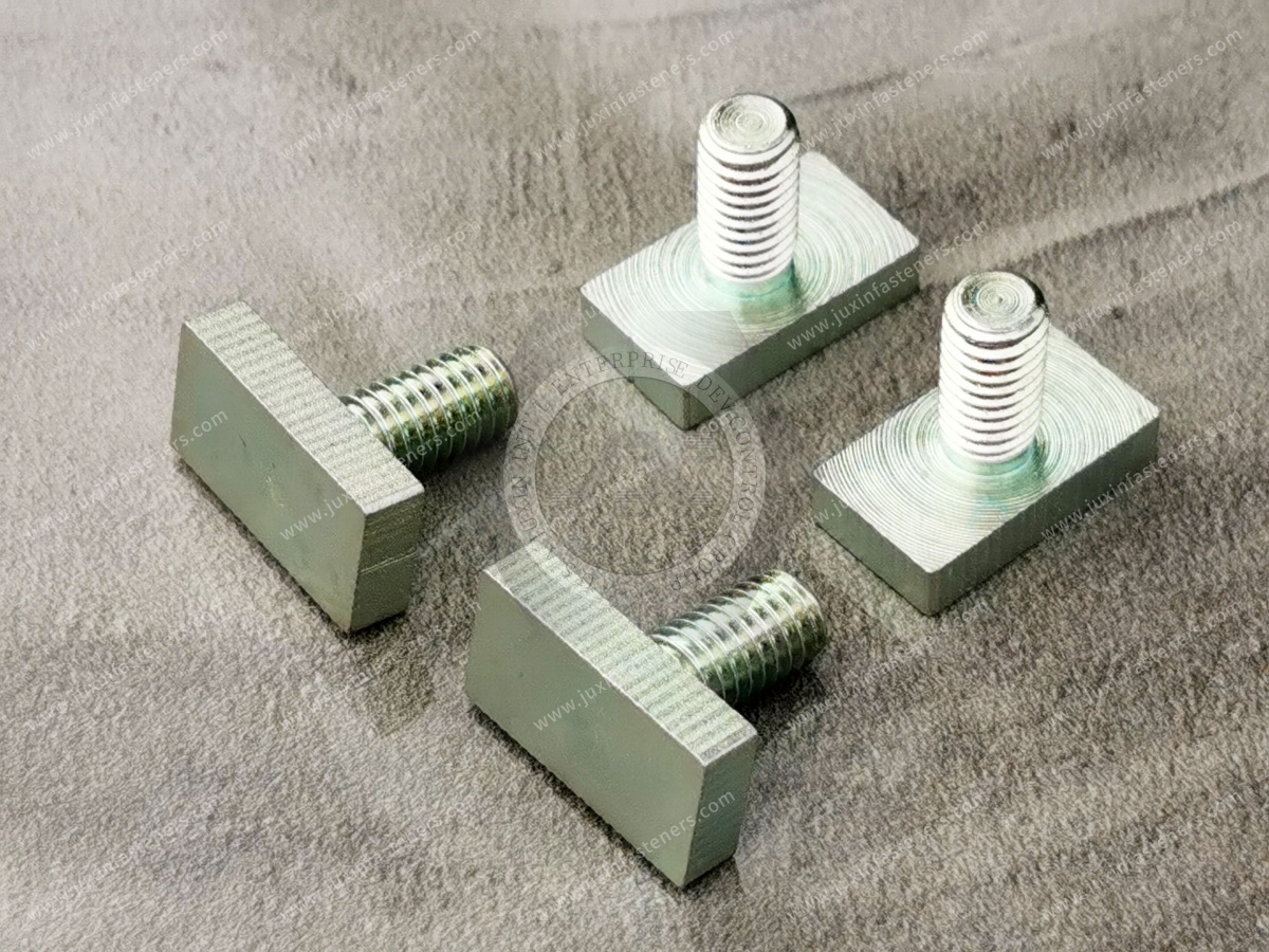
Product Packaging
Packaging Standard
At Juxin Fasteners, we apply standardized export packaging to ensure product protection, traceability, and compliance with international logistics requirements.
1. Standard Export Packaging
Unless otherwise specified, all products will be packed according to our factory standard export packaging, which includes:
Moisture-resistant inner protection
Poly bag or small box packing as required
Reinforced export cartons
Clear labeling with part number, specification, batch number, and quantity
Palletizing for sea or air shipment when necessary
Our standard packaging is designed to ensure safe transportation, efficient warehousing, and long-distance international shipping.
2. Customized Packaging Options
We also provide customized packaging solutions according to customer requirements, including but not limited to:
Private labeling
Customized barcodes
Specific carton dimensions
Retail packaging
Special pallet configuration
Customer-specific marking and identification
So that you know, customized packaging may involve additional costs and extended lead time depending on the complexity of the requirements.
3. Compliance & Quality Assurance
All packaging processes are controlled under our ISO 9001 quality management system to ensure consistency, traceability, and product integrity throughout the supply chain.
Product Pictures
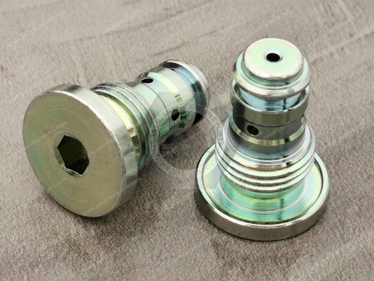
Hot Products
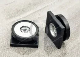
Automotive Screw-Type Retainers: Engineering, Thread Integration & OEM Sourcing Guide
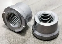
Automotive Spoiler Slide Bolts: Engineering, Mounting Design & OEM Sourcing Guide
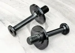
Automotive Seat Systems: Fastening Engineering, High-Strength Hardware & OEM Sourcing Guide
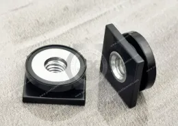
Automotive Fastener Sourcing & Specification Guide for OEM Buyers
Contact Us
Tel.:
+86 020 8621 0320
+86 020 3121 6067
E-mail:
Technical Support:
Navigation
SEND INQUIREY