Call Us
+86 136 6007 9809
Call Us
+86 136 6007 9809

Power electronics manufacturers, switchgear builders, electrical enclosure fabricators and industrial equipment OEMs frequently need reliable internal threads in thin sheet metal.
In many electrical cabinets, inverter housings, control panels and power distribution enclosures,
the available sheet thickness is insufficient for a conventional tapped hole to provide the required thread engagement.
Product Specification
Welded nuts, loose hex nuts and blind rivet nuts can provide alternatives, but each fastening method introduces different requirements for installation access,
panel geometry, assembly sequence and long-term performance.
Self-clinching nuts provide permanent internal threads in suitable sheet metal through a controlled mechanical press-installation process.
JUXIN FASTENERS supplies self-clinching fasteners for industrial sheet metal assemblies, including self-clinching nuts, studs and standoffs,
with material, dimensional and application requirements reviewed according to the customer's drawing.
For engineering and procurement teams, the critical selection question is not simply whether a nut has the correct thread.
It is whether the complete combination of fastener geometry, panel material, panel hardness, sheet thickness,
installation hole and installation process can produce a reliable mechanical connection.
This guide explains how to evaluate self-clinching nuts for electrical equipment and industrial enclosures, including installation design,
failure modes, alternative fastening technologies and OEM sourcing requirements.
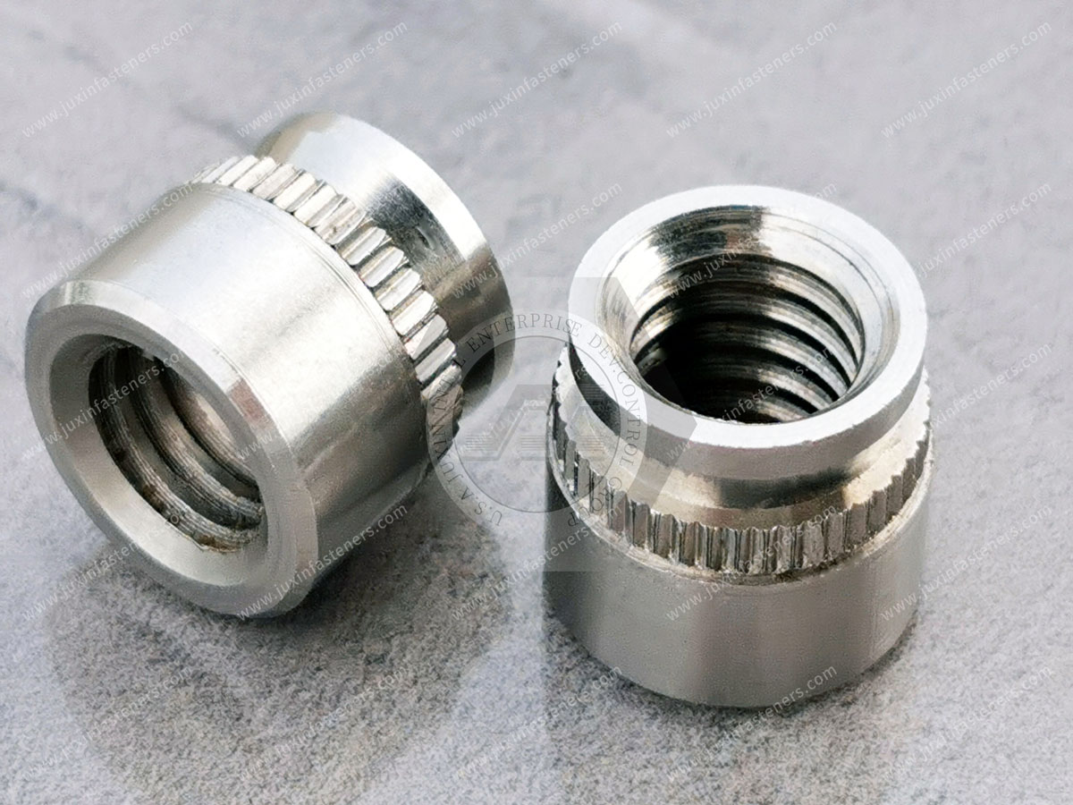
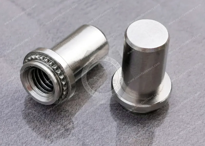
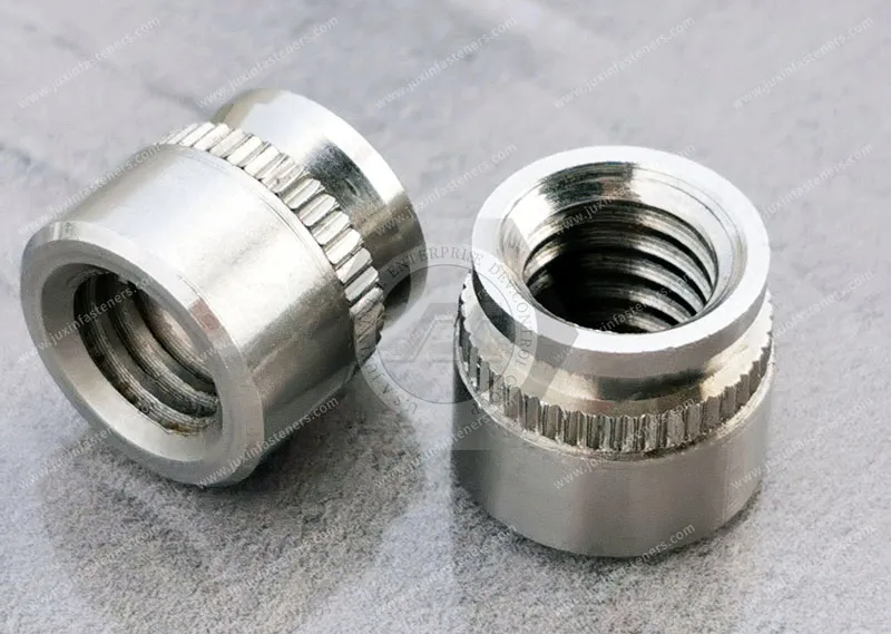
A self-clinching nut is a threaded fastener designed to become mechanically retained in a suitable sheet metal panel when installed using controlled pressing force.
It is also commonly called a:
Clinch nut
Press-in nut
Self-clinching threaded nut
Sheet metal clinch nut
Captive threaded nut
In typical designs, the fastener incorporates a displacer or clinching feature and an undercut or retention geometry.
During installation, the fastener is pressed into a correctly prepared hole.
The surrounding sheet material plastically deforms into the fastener's retention geometry, creating mechanical resistance to axial displacement and rotation.
Unlike a conventional loose nut, the installed component remains attached to the panel before final equipment assembly.
However, self-clinching nuts are not suitable for every material or panel thickness.
Their performance depends on the actual fastener and sheet metal combination.
Power electronics and electrical enclosure assemblies often require:
Compact sheet metal structures
Repeatable threaded attachment points
Reduced loose-hardware handling
Consistent equipment assembly
Serviceable covers and brackets
Reliable mounting interfaces
Controlled panel flatness
Defined electrical bonding or isolation paths
Potential applications include:
Industrial inverter enclosures
Power conversion equipment
Electrical distribution cabinets
Switchgear housings
Battery energy storage system enclosures
UPS equipment cabinets
Industrial control panels
Power supply chassis
Motor drive enclosures
Renewable energy converter housings
Telecom power cabinets
Industrial automation equipment
Self-clinching nuts may provide an effective solution where the panel is suitable for press installation and the fastening interface must be accessible from the assembly side.
A self-clinching nut provides two distinct functions:
Function 1: Internal Thread
The nut provides a threaded interface for a mating screw or bolt.
Function 2: Panel Retention
The clinching geometry holds the nut in the sheet metal.
These functions should not be confused.
A nut may have adequate thread strength but insufficient retention in the panel.
Alternatively, the nut may remain securely clinched while the mating screw or internal thread fails.
Therefore, engineering evaluation must consider:
Internal thread strength
Axial push-out resistance
Rotational torque-out resistance
Panel deformation
Joint loading
Installation conditions
A reliable threaded assembly requires all relevant interfaces to function together.
Many industrial enclosures use relatively thin steel or aluminum sheet.
When a hole is tapped directly into thin sheet metal, the available thread engagement may be limited.
The resulting connection may be vulnerable to thread stripping, depending on the material, thickness, screw size and applied load.
Self-clinching nuts introduce a separate threaded component with a defined thread engagement length.
This can provide a practical fastening solution without requiring a thicker panel.
However, the fastener must be compatible with the actual sheet thickness.
A self-clinching nut cannot compensate for an unsuitable substrate simply because its internal thread is strong.
Before choosing a clinch nut, verify:
Nominal thread size
Panel thickness
Panel material
Panel hardness
Installation hole diameter
Minimum distance from the hole to the panel edge
Available installation access
Required push-out and torque-out performance
The applicable installation specifications must be taken from the selected fastener design.
Self-clinching technology depends on controlled plastic deformation of the host sheet.
The sheet must be sufficiently formable relative to the clinching features of the fastener.
This creates an important material-selection requirement.
A self-clinching nut that installs successfully in mild steel may not perform identically in:
Aluminum sheet
Stainless steel sheet
High-strength steel
Hardened sheet metal
Coated steel
Other specialized panel materials
The material combination must be evaluated before production.
A stainless steel nut is not automatically suitable for installation into stainless steel sheet.
Some stainless steel sheets are too hard for particular self-clinching nut designs.
The appropriate fastener may require a different material, hardness or retention geometry.
The correct selection depends on the fastener manufacturer's installation specification and the actual panel hardness.
Do not specify stainless steel self-clinching nuts solely because the enclosure is made from stainless steel.
An enclosure engineer may choose stainless steel for corrosion resistance.
But the same material selection can create challenges for mechanical clinching.
The design must satisfy two separate conditions:
Environmental Requirement: The fastener must be suitable for the service environment.
Installation Requirement: The fastener must be compatible with the host sheet material and hardness.
A corrosion-resistant fastener that cannot clinch reliably is not an acceptable solution.
Where these requirements conflict, engineers may need to evaluate:
A different clinch nut design
A different panel material or local panel condition
A blind rivet nut
A weld nut
A captive nut assembly
A redesigned mounting interface
The fastening architecture should be selected before finalizing the enclosure drawing.
The installation hole is a critical feature in a self-clinching joint.
An incorrect hole diameter can reduce mechanical retention or prevent proper installation.
Potential problems include:
Oversized holes
Undersized holes
Excessive burrs
Hole distortion
Incorrect hole position
Inadequate edge distance
Damaged panel surfaces
Unlike a conventional clearance hole, a clinch nut installation hole must meet the requirements of the selected fastener.
For typical self-clinching installations, the OEM should control:
Hole diameter
Hole roundness
Burr condition
Panel flatness
Edge distance
Hole-to-hole spacing
Installation-side orientation
The correct hole preparation depends on the specific fastener design.
A supplier may deliver clinch nuts that meet every dimensional requirement.
However, if the enclosure fabricator produces an oversized installation hole, the assembled joint may fail.
This illustrates an important distinction:
Fastener Quality ≠ Installed Joint Quality
The final performance depends on:
Fastener + Sheet Material + Hole Geometry + Installation Process
For OEM supplier qualification, the complete installed joint should be evaluated.
Push-out resistance describes the axial force required to displace an installed self-clinching fastener from the panel under a defined test arrangement.
It is an important indicator of mechanical retention.
However, push-out resistance depends on:
Fastener design
Sheet thickness
Sheet material
Sheet hardness
Installation hole
Installation force
Test configuration
A push-out value from one sheet material should not automatically be applied to another.
Consider a clinch nut used to secure an internal mounting bracket in an electrical cabinet.
The joint may experience axial loading during:
Equipment assembly
Service removal
Cable installation
Bracket loading
Maintenance
The designer should determine whether the installed nut has sufficient retention for the expected loading conditions.
Torque-out resistance describes the rotational resistance of an installed clinch nut within the host sheet under a defined test condition.
If the clinching interface cannot resist the applied torque, the nut may rotate inside the panel.
This can make the assembly difficult or impossible to tighten or remove.
Potential causes include:
Incorrect installation hole
Insufficient installation force
Incompatible sheet hardness
Incorrect fastener selection
Panel deformation
Excessive assembly torque
The tightening torque applied to a mating screw is not identical to the torque-out resistance of the clinch nut.
During tightening, the actual load transferred to the installed nut depends on the joint configuration, friction and screw behavior.
The engineer should distinguish between:
Required screw tightening torque
Internal thread capacity
Installed nut torque-out resistance
Panel deformation
Clamp load
These are related but separate design considerations.
A high-strength screw does not automatically make the clinched joint stronger.
Self-clinching nuts are generally installed using a controlled pressing process.
The correct installation force depends on:
Fastener design
Fastener size
Sheet material
Sheet thickness
Installation tooling
Panel support
Insufficient force can prevent complete clinching.
Excessive force can deform the panel or damage the fastener.
The correct force should be established from the applicable fastener specification and verified on the actual assembly.
Depending on production requirements, suitable equipment may include:
Mechanical presses
Hydraulic presses
Servo-controlled presses
Automated insertion systems
Equipment selection should consider production volume, accessibility, force control and process monitoring.
A common misconception is that increasing press force will always improve clinch nut retention.
In reality, excessive force may cause:
Panel distortion
Local thinning
Fastener deformation
Damage to surrounding features
Poor assembly appearance
The goal is controlled material displacement into the fastener's retention geometry.
It is not simply maximum pressing force.
Power electronics enclosures may require controlled panel flatness for:
Cover fit
Sealing interfaces
Mounting brackets
Door alignment
Equipment assembly
Self-clinching nuts avoid the localized welding heat associated with weld nuts.
However, press installation still introduces mechanical forces into the sheet.
Incorrect installation can produce:
Panel distortion
Local indentation
Surface marking
Misalignment
Therefore, clinch installation should not be described as universally distortion-free.
The actual result depends on the fastener, tooling and panel design.
Both technologies provide permanent threaded attachment points, but they use different installation methods.
| Selection Factor | Self-Clinching Nuts | Weld Nuts |
|---|---|---|
| Installation method | Mechanical pressing | Welding |
| Heat input | No intentional welding heat | Localized welding heat |
| Host material requirement | Suitable formable sheet | Weldable material and compatible process |
| Installation access | Press and tooling access required | Welding access required |
| Retention mechanism | Mechanical interlock | Weld joint |
| Coating considerations | Installation sequence must be reviewed | Welding may affect local coatings |
| Key validation | Push-out, torque-out and panel condition | Weld integrity and applicable joint testing |
Neither technology is universally superior.
The correct choice depends on:
Sheet material
Thickness
Production process
Available equipment
Joint loads
Coating sequence
Inspection requirements
Weld nuts may be appropriate when:
The fabrication process already includes welding
The sheet and nut materials are weld-compatible
The required joint design favors welding
Press installation is impractical
Self-clinching nuts may be attractive when:
The sheet is compatible with clinching
Welding heat is undesirable
Press access is available
A permanent threaded insert is required
The production sequence supports press installation
Blind rivet nuts, also called rivet nuts or threaded inserts for blind-side installation, provide internal threads through a different retention mechanism.
A rivet nut is installed by deforming its body to grip the host material.
This can be useful where access is available from only one side.
| Selection Factor | Self-Clinching Nuts | Blind Rivet Nuts |
|---|---|---|
| Typical installation | Press installation | Pull-type setting tool |
| Installation access | Access required for press tooling and support | One-sided access possible |
| Retention mechanism | Sheet flows into clinching features | Rivet nut body deforms against sheet |
| Sheet compatibility | Controlled by material hardness and thickness | Controlled by grip range and hole geometry |
| Common use | Sheet metal fabrication | Blind-side assembly and retrofit |
| Key validation | Push-out and torque-out | Spin-out, pull-out and setting quality |
For an enclosed cabinet or completed box section, blind rivet nuts may be more practical where opposing-side tooling access is unavailable.
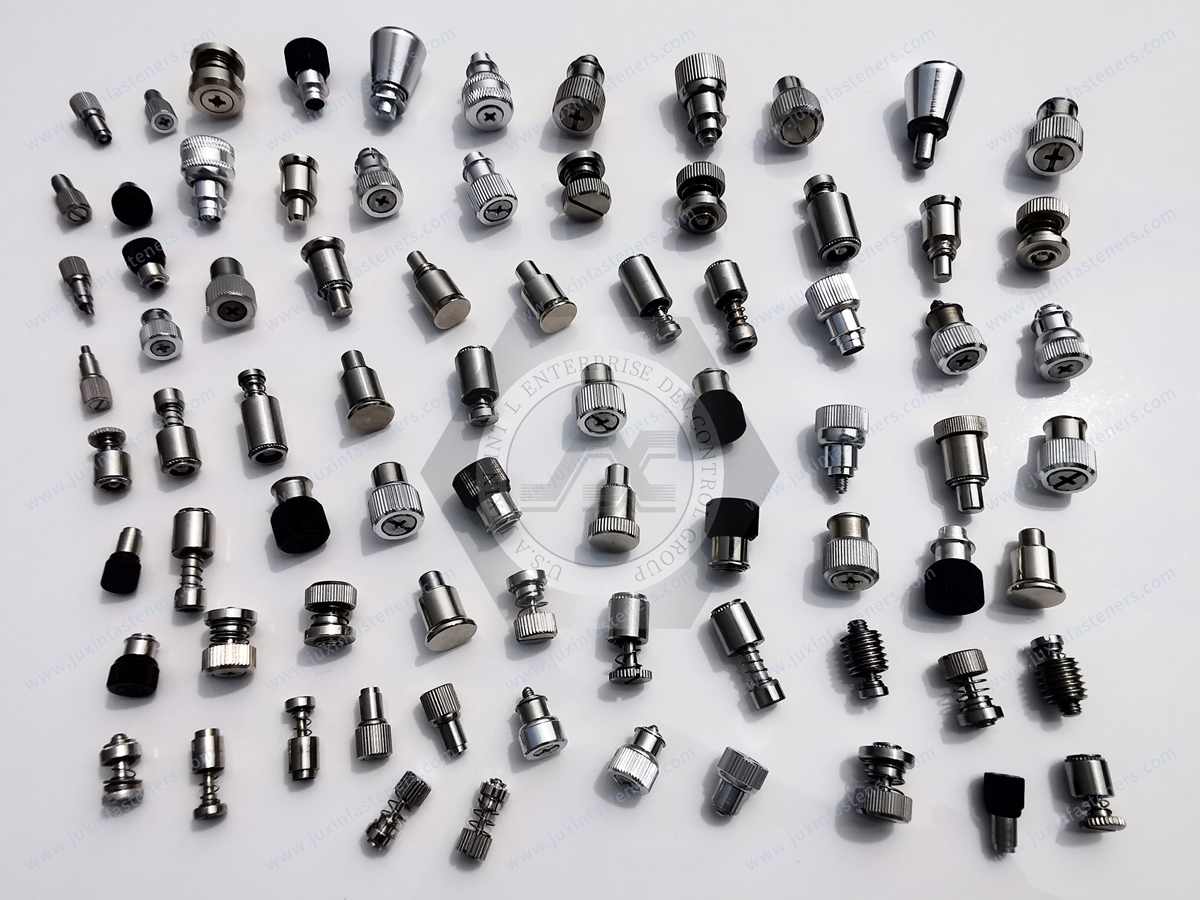
Consider two electrical enclosures.
Enclosure A: A flat sheet metal panel before final forming.
Enclosure B: A completed cabinet with access from only one side.
Self-clinching nuts may be practical for Enclosure A because press tooling can access and support the installation area.
For Enclosure B, a blind rivet nut may be easier to install.
The required assembly sequence can therefore determine the fastening method before mechanical strength is compared.
Cage nuts provide a threaded nut retained within a cage or carrier.
Depending on the design, the nut may allow some positional movement.
This can help accommodate assembly alignment.
Self-clinching nuts generally provide a fixed threaded position relative to the panel.
Choose a fixed self-clinching thread where:
Precise mounting location is required
The panel is suitable for clinching
Assembly alignment is controlled
Evaluate a floating cage nut where:
Alignment variation is expected
A removable or replaceable nut is desirable
The mounting architecture supports the cage
These solutions should not be treated as direct substitutes without reviewing the assembly.
A self-clinching nut primarily provides an internal thread.
A self-clinching standoff provides a threaded or unthreaded mounting interface with a defined spacing height.
For power electronics, this distinction is important.
A PCB or power module may require a controlled distance from the chassis.
In that case, a self-clinching standoff may be more suitable than a clinch nut combined with separate spacers.
An M4 internal thread can appear in several product families:
Self-clinching nut
Self-clinching standoff
Blind rivet nut
Weld nut
Cage nut
All may accept an M4 screw.
But they solve different assembly problems.
The engineer should first identify:
Threaded Attachment + Spacing + Installation Access + Panel Material + Service Requirement
Only then should the specific fastener be selected.
Industrial inverters often contain:
Power electronic modules
Internal mounting brackets
Electrical control boards
Cable-management components
Metal chassis structures
Protective covers
Self-clinching nuts may be used to secure selected brackets and panels.
The designer should consider:
Sheet material
Thread size
Required mounting load
Electrical isolation
Service access
Thermal environment
Corrosion exposure
A self-clinching nut is a mechanical fastening component.
Its presence does not establish electrical insulation or grounding compliance.
Switchgear and electrical distribution cabinets may require threaded attachment points for:
Internal brackets
Equipment supports
Cover panels
Accessories
Cable-management hardware
The correct fastener depends on the specific mounting location.
Important requirements may include:
Panel thickness
Structural loading
Vibration
Assembly access
Corrosion protection
Electrical bonding requirements
Electrical safety requirements must be addressed at the complete equipment level.
Battery energy storage systems can include numerous sheet metal assemblies.
Potential applications include:
Equipment covers
Internal support brackets
Control electronics enclosures
Cable-management assemblies
Non-cell structural accessories
Fastener selection may need to consider:
Vibration
Thermal environment
Corrosion exposure
Service access
Electrical isolation
Grounding design
A self-clinching nut should not be assumed suitable for high-voltage electrical interfaces without application-specific engineering review.
UPS and industrial power supply equipment may use clinch nuts for:
Sheet metal brackets
Access covers
Internal equipment mounts
Structural accessories
For frequently serviced assemblies, engineers should also evaluate:
Screw access
Repeated assembly
Thread wear
Torque control
Nut retention
The complete joint should remain serviceable without damaging the host panel.
Electrical enclosures may require conductive connections between selected components.
However, self-clinching nuts should not automatically be treated as certified grounding components.
Electrical bonding performance depends on:
Fastener material
Panel material
Surface coating
Contact geometry
Installation condition
Corrosion
Joint design
Paint, powder coating or other insulating surface layers may affect electrical continuity.
Where a self-clinching nut forms part of an intentional bonding path, the complete joint must be evaluated against the applicable electrical design requirements.
A clinch nut may pass push-out and torque-out testing.
That does not prove the assembly provides the required electrical bonding resistance.
Mechanical and electrical verification are different activities.
For grounding applications, engineers should define:
Intended current path
Contact surfaces
Coating condition
Bonding resistance requirement
Applicable equipment standard
Verification method
A mechanically secure joint may still be electrically unsuitable.
Electrical cabinet designs may include electromagnetic compatibility requirements.
However, self-clinching nuts do not automatically create an effective EMI shielding or grounding system.
EMC performance depends on the complete enclosure architecture, including:
Conductive continuity
Gaskets
Cable entry
Panel joints
Grounding
Bonding
Shielding design
Fasteners are one element of this system.

Electrical enclosures may operate in:
Indoor industrial facilities
Humid environments
Outdoor equipment installations
Coastal locations
Chemical-processing facilities
Material and coating selection should follow the actual service environment.
Potential options may include:
Carbon steel with suitable protective coating
Stainless steel where compatible
Customer-specified surface treatments
However, corrosion resistance must be considered together with clinching compatibility.
Carbon steel clinch nuts may be suitable for selected steel or aluminum sheet applications when the fastener design and panel properties are compatible.
Selection should consider:
Mechanical properties
Fastener hardness
Sheet hardness
Surface coating
Environmental exposure
Installation performance
A carbon steel clinch nut should not be selected solely by thread size.
Stainless steel may be considered where corrosion resistance is required.
However, stainless steel clinch nut selection requires review of:
Fastener grade
Fastener hardness
Sheet material
Sheet hardness
Installation geometry
Corrosion environment
Austenitic stainless steel designation alone does not establish suitability for a particular clinching application.
A purchasing specification stating:
M4 Stainless Steel Self-Clinching Nut
is incomplete.
It does not define:
Exact fastener geometry
Stainless grade
Panel material
Panel hardness
Minimum sheet thickness
Installation hole
Required retention performance
For accurate sourcing, the customer should provide the actual fastener specification or drawing.
Potential finish requirements may include:
Zinc-based protective coatings
Zinc-nickel coatings
Stainless steel passivation where appropriate
Customer-specific finishes
The selected treatment should be evaluated for:
Base material compatibility
Corrosion requirements
Dimensional effects
Installation behavior
Electrical contact requirements
Coating performance must not be represented by an unsupported universal salt spray rating.
ASTM B117 provides a neutral salt spray test method, but test results do not directly predict service life in every real-world environment.
The production sequence can affect the final assembly.
For example:
Route A: Clinch installation before panel coating.
Route B: Clinch installation after panel coating.
Each route may create different considerations.
Installation before coating can expose the assembled nut and panel to subsequent finishing processes.
Installation after coating can affect the local finish during pressing and may influence electrical contact.
The correct sequence depends on:
Coating type
Fastener design
Installation requirements
Appearance
Corrosion protection
Electrical bonding requirements
A clinch nut installed successfully in bare sheet metal may not perform identically when installed after a thick surface coating.
Likewise, installing before coating may introduce masking or thread-protection requirements.
The OEM should define the coating and installation sequence before production approval.
Potential failure modes include:
Nut rotation in the panel
Axial push-out
Panel deformation
Hole enlargement
Incorrect seating
Thread damage
Corrosion
Loss of electrical continuity where bonding is required
These failures may arise from the fastener, panel, installation process or complete assembly.
Possible contributing factors include:
Oversized hole
Incorrect panel hardness
Insufficient installation force
Incorrect nut selection
Damaged clinching geometry
The corrective action should be based on the actual cause.
Increasing screw tightening torque is not a remedy for inadequate clinch retention.
Possible contributing factors include:
Inadequate clinching
Incorrect sheet thickness
Hole geometry
Excessive axial loading
Incompatible material combination
The installed joint should be evaluated under the relevant loading condition.
Possible contributing factors include:
Excessive installation force
Insufficient panel support
Poor tooling alignment
Inadequate edge distance
Thin or flexible panel geometry
The solution may involve tooling changes, fastener selection or panel redesign.
Thread damage may result from:
Incorrect mating screw
Cross-threading
Excessive tightening torque
Damaged threads
Inappropriate assembly method
The nut's retention in the panel and its internal thread performance should be evaluated separately.
When a clinch nut fails, the engineer should identify which interface failed.
Interface A: Nut-to-panel retention.
Interface B: Nut internal thread-to-screw engagement.
Interface C: Screw-to-joint clamp load.
Interface D: Panel-to-mounted component contact.
Each interface has different failure mechanisms.
Replacing the nut without identifying the failed interface may not solve the problem.
| Design Requirement | Primary Engineering Question | Possible Selection Direction |
|---|---|---|
| Thin sheet metal | Is the sheet compatible with clinching? | Self-clinching nut |
| One-sided installation | Is rear-side tooling access unavailable? | Blind rivet nut |
| Welded fabrication | Is welding already part of production? | Weld nut |
| Positional adjustment | Is thread float required? | Cage nut or floating nut design |
| Controlled component spacing | Is a defined mounting height required? | Self-clinching standoff |
| Male threaded attachment | Is a permanent stud required? | Self-clinching stud |
| Electrical bonding | Is a verified conductive path required? | Validate complete joint |
| Outdoor corrosion exposure | What material and finish are required? | Application-specific selection |
This comparison helps prevent incorrect product substitutions.
Self-clinching nut selection should begin before the enclosure drawing is released.
Design engineers should confirm:
Panel material
Panel hardness
Minimum sheet thickness
Installation hole diameter
Edge distance
Fastener orientation
Tooling access
Installation sequence
Required retention
Surface finish
The design should also account for nearby bends, embossments, cutouts and other features that may interfere with installation tooling.
A fastener may fit within the final enclosure geometry.
However, the manufacturing process may not provide sufficient access for the installation press and supporting tooling.
This is particularly important near:
Deep bends
Narrow channels
Box sections
Reinforcing ribs
Closely spaced mounting points
Therefore, installation access must be reviewed in the fabrication stage, not only in the finished 3D assembly.
Design and structural engineers should evaluate the following sequence.
Identify the required metric or inch thread.
Specify steel, aluminum, stainless steel or another substrate.
Verify compatibility with the proposed fastener.
Check the minimum installation thickness for the selected design.
Use the applicable fastener-specific hole requirements.
Confirm sufficient material around the installation location.
Verify press and tooling clearance.
Consider push-out, torque-out and joint loading.
Specify corrosion protection and coating sequence.
Evaluate installation and functional performance on the actual panel.
This process helps avoid late-stage design changes.
For accurate quotation and technical review, procurement teams should provide:
Product drawing or reference specification
Thread size
Fastener dimensions
Fastener material
Panel material
Panel hardness where available
Panel thickness
Installation hole diameter
Surface finish
Corrosion requirement
Required push-out resistance
Required torque-out resistance
Installation process
Prototype quantity
Annual purchasing quantity
Packaging requirements
Required inspection documentation
For custom or nonstandard clinch nuts, a 2D drawing and available 3D model are recommended.
Do not compare only:
M4 Self-Clinching Nut + Material + Price.
Compare:
Fastener geometry
Panel compatibility
Installation hole
Minimum sheet thickness
Material and hardness
Surface finish
Installation requirements
Retention performance
Drawing tolerances
Sample approval process
Production consistency
Documentation requirements
Two nuts with the same thread size may not be interchangeable.
A replacement self-clinching nut may accept the same mating screw.
But it may have a different:
Clinching profile
Installation hole requirement
Minimum sheet thickness
Installation force
Push-out resistance
Torque-out resistance
Therefore, a substitute supplier should not be approved solely because the thread and external appearance are similar.
The actual installed performance must be reviewed.
For an existing self-clinching nut, a practical qualification process can follow:
Existing Part Review → Drawing Review → Panel Compatibility Review → Installation Hole Verification → Sample → Press Installation
→ Push-Out / Torque-Out Evaluation → Assembly Test → Golden Sample Approval → Production
The OEM should define the applicable acceptance criteria.
Where the fastener is part of an electrical bonding path, electrical continuity validation should also be considered.
For drawing-specific self-clinching nuts, the approved sample should be linked to:
Drawing revision
Material specification
Surface finish
Critical dimensions
Installation conditions
Required functional results
The purpose is to establish a controlled production reference.
Sample approval should not be based on visual appearance alone.
Depending on the project, inspection may include:
Dimensional verification
Thread inspection
Material verification
Surface finish inspection
Installation evaluation
Push-out testing
Torque-out testing
Panel deformation review
Electrical bonding verification where specified
Additional reports or certifications should be agreed during RFQ review.
EN 10204 inspection documents, when required and applicable, should be specified rather than assumed to accompany every order.
Depending on the component and application, relevant references may include:
ISO metric thread standards
ASME/ANSI inch-thread standards
Applicable ISO or ASTM material specifications
ISO 3506 series for relevant stainless steel fastener mechanical-property requirements within its scope
ASTM B117 for specified salt spray testing
EN 10204 for agreed inspection document requirements
Applicable electrical equipment standards selected by the OEM
Self-clinching nut installation geometry and retention performance are often controlled by product-specific specifications and
customer drawings rather than a single universal dimensional standard.
JUXIN FASTENERS does not assume that every clinch nut complies with every ISO, DIN, ASME, BS, EN or ASTM standard.
The applicable requirements should be defined for the actual product.
Standard self-clinching nuts cover many sheet metal applications.
However, custom requirements may arise from:
Nonstandard threads
Special external dimensions
Restricted installation space
Unusual panel thickness
Special material requirements
Customer-specific retention requirements
Special surface finish
Drawing-controlled geometry
JUXIN FASTENERS can review custom self-clinching nut requirements according to the drawing and actual manufacturing feasibility.
Specialized configurations should be confirmed during technical review rather than assumed to be standard stocked products.
For power electronics and enclosure manufacturers, an effective sourcing process should connect engineering and procurement.
A practical development sequence is:
Application Requirement → Panel & Thread Review → Fastener Selection → Drawing Confirmation → Sample → Installation Validation
→ Functional Testing → Golden Sample Approval → Production
This reduces the risk of selecting a fastener that meets the purchase description but fails in the actual sheet metal assembly.
For related fastening requirements, explore the following JUXIN FASTENERS solutions.
A broader guide to self-clinching fastener selection for thin sheet metal equipment.
For applications requiring permanent mounting threads combined with controlled component spacing.
For applications requiring a permanently installed male threaded attachment point.
For threaded fastening where installation access is limited to one side.
For welded threaded attachment in suitable fabricated structures.
For rack and cabinet mounting systems requiring captive threaded hardware.
These related solutions provide alternative fastening paths according to the actual assembly requirement.
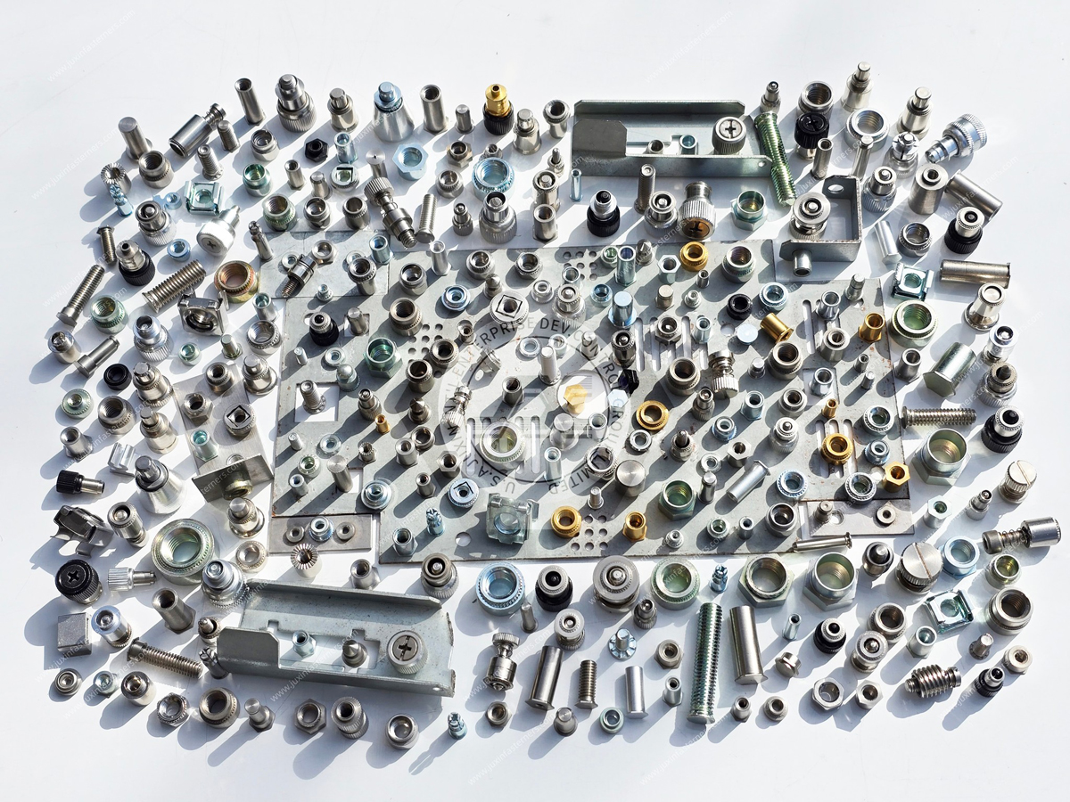
Are you sourcing self-clinching nuts for:
Power electronics enclosures
Industrial inverters
Switchgear cabinets
Electrical distribution equipment
Battery energy storage enclosures
UPS systems
Telecom power cabinets
Industrial control panels
Sheet metal equipment housings
JUXIN FASTENERS can review standard and drawing-based self-clinching nut requirements for industrial OEM applications.
For an efficient technical review, send:
Drawing + Thread Size + Panel Material + Panel Thickness + Installation Hole + Surface Finish + Required Retention + Quantity
If you are qualifying an alternative supplier, include the existing product specification and relevant installation requirements.
The objective is to select a self-clinching nut that works in the actual panel—not merely one that matches the nominal thread size.
JUXIN FASTENERS
Website: www.juxinfasteners.com
Engineering & RFQ: info@juxinfasteners.com
Send your drawing and project requirements for technical review and quotation.
Product Packaging
Packaging Standard
At Juxin Fasteners, we apply standardized export packaging to ensure product protection, traceability, and compliance with international logistics requirements.
1. Standard Export Packaging
Unless otherwise specified, all products will be packed according to our factory standard export packaging, which includes:
Moisture-resistant inner protection
Poly bag or small box packing as required
Reinforced export cartons
Clear labeling with part number, specification, batch number, and quantity
Palletizing for sea or air shipment when necessary
Our standard packaging is designed to ensure safe transportation, efficient warehousing, and long-distance international shipping.
2. Customized Packaging Options
We also provide customized packaging solutions according to customer requirements, including but not limited to:
Private labeling
Customized barcodes
Specific carton dimensions
Retail packaging
Special pallet configuration
Customer-specific marking and identification
So that you know, customized packaging may involve additional costs and extended lead time depending on the complexity of the requirements.
3. Compliance & Quality Assurance
All packaging processes are controlled under our ISO 9001 quality management system to ensure consistency, traceability, and product integrity throughout the supply chain.
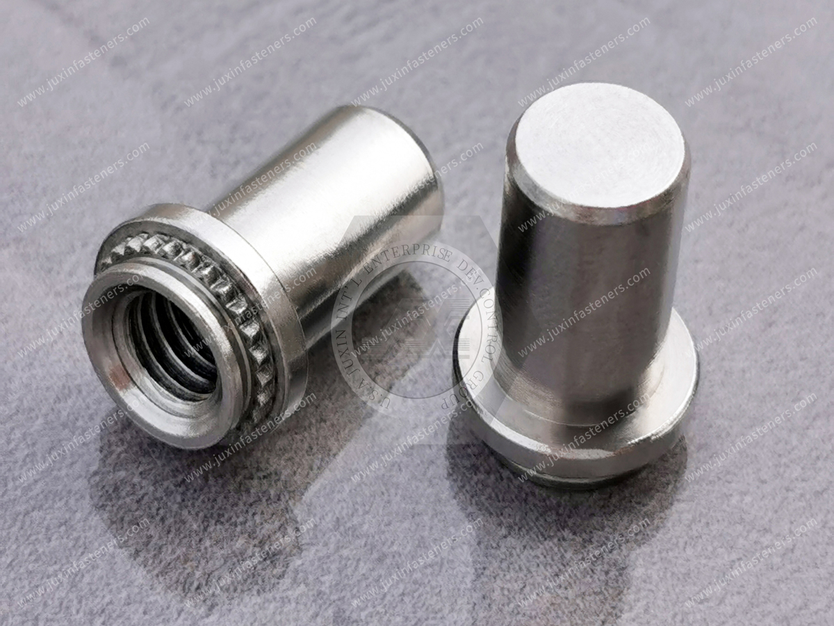
Product Pictures
Contact Us
Tel.:
+86 020 8621 0320
+86 020 3121 6067
E-mail:
Technical Support:
Navigation
SEND INQUIREY