
Call Us
+86 136 6007 9809
Call Us
+86 136 6007 9809

Sep. 27, 2026
Adjustable cable clamps and standoff harness clips provide controlled routing and retention for wire harnesses, electrical cables, sensor leads,
flexible tubing, and selected fluid lines in automotive, electric vehicle, industrial automation, power electronics, robotics, machinery, telecommunications, and other OEM equipment.
Unlike fixed-diameter P-clips that are selected around a defined cable or bundle envelope, adjustable cable clamps can incorporate ratcheting straps,
multi-position locking teeth, flexible latches, or releasable locking mechanisms that accommodate a defined range of bundle sizes.
Standoff harness clips add another functional dimension: they position the harness away from the mounting surface.
This can help route wiring around or away from:
sheet-metal edges
structural ribs
weld features
moving components
adjacent connectors
busbars
cooling hardware
other cable routes
However, adjustability does not eliminate the need for engineering selection.
A clamp that can physically close around a bundle is not automatically the correct clamp for that harness.
The more reliable selection path is:
Bundle Envelope → Harness Function → Required Movement → Clamp Type → Grip Level → Standoff Height
→ Mounting Interface → Dynamic Load → Temperature → Material → Serviceability → Validation
Juxin Fasteners supplies standard and custom adjustable cable clamps, standoff harness clips, nylon P-clips, cable retainers, fir tree fasteners, cable tie mounts,
wire-routing hardware, and drawing-based custom molded plastic components for global OEM applications.
Engineering and procurement teams can submit existing manufacturer part numbers, physical samples, bundle dimensions, panel specifications,
2D drawings, 3D CAD models, mounting-interface requirements, material requirements, and application conditions for technical and commercial evaluation.
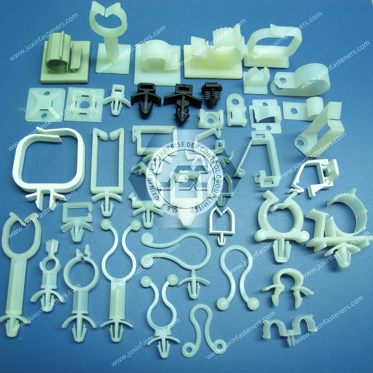
An adjustable cable clamp is a cable-retention component designed to accommodate a specified range of bundle diameters or bundle envelopes rather than one fixed closed-loop dimension.
Depending on the design, adjustment may be achieved using:
ratchet teeth
multiple latch positions
flexible strap engagement
indexed locking positions
reusable release mechanisms
This makes adjustable clamps useful where:
bundle size varies between product configurations
multiple harness variants share one chassis
additional conductors may be introduced
prototype routing changes frequently
service access is required
a product platform uses related harness architectures
Adjustability should nevertheless remain within the component's intended working range.
These two products solve related but different routing problems.
A Nylon P-Clip surrounds a defined cable or bundle diameter and is typically secured through a mounting hole.
It may be appropriate where:
bundle diameter is well controlled
routing is permanent
a simple closed-loop architecture is preferred
An adjustable clamp provides multiple closing positions.
It may be useful where:
bundle diameter varies
assembly configuration changes
service access is needed
one clamp must accommodate a defined sizing range
Therefore:
Adjustability ≠ Automatically Better Retention
The correct choice depends on the harness and assembly architecture.
A standoff harness clip incorporates a defined offset between the harness-retention feature and the mounting surface.
Conceptually:
Panel → Mounting Interface → Standoff → Cable Retention Feature → Harness
The standoff controls harness position in three-dimensional assembly space.
This makes standoff height a functional engineering dimension rather than simply part of the clip's overall size.
Different adjustable and standoff clamps use different retention architectures.
The correct design should be selected according to:
bundle size
cable type
mounting interface
service requirements
available packaging space
environmental conditions
Ratchet-style clamps use a flexible strap with a sequence of locking teeth or engagement features.
The installer closes the strap until the intended bundle retention is reached.
Potential advantages include:
accommodation of multiple bundle sizes
progressive adjustment
compact packaging
simplified assembly
However, the final locking position should not create excessive cable-jacket compression.
Some cable holders provide discrete locking positions rather than a continuous ratchet range.
These may be useful where a limited number of known bundle configurations must share the same component.
The selected locking position should be validated for each harness configuration.
Releasable clamps incorporate a latch that can be intentionally opened.
These can be useful for:
prototype development
field maintenance
serviceable equipment
modular wiring
harness modification
However:
Releasable ≠ Unlimited Reuse
Repeated latch cycling can change retention behavior depending on material, geometry, temperature, and deflection.
Expected service cycles should therefore be defined where repeated opening is important.
Standoff clips elevate the harness from the mounting surface.
Potential applications include routing around:
panel flanges
stamped ribs
weld seams
adjacent hardware
heat-generating equipment
other harnesses
The standoff must provide enough clearance without unnecessarily increasing bending moment at the mounting point.
Some adjustable clamps incorporate a push-in mounting feature for installation into a panel hole.
Possible retention geometries include:
fir tree features
flexible barbs
snap legs
other push-in profiles
Panel-hole diameter and panel thickness become critical functional dimensions.
Screw-mounted clamps use a clearance or mounting hole for attachment with a separate screw or bolt.
These designs can be useful where:
service removal is required
threaded chassis points already exist
a defined mechanical attachment is preferred
The mounting screw and clamp geometry should be evaluated as a joint.
Some clips engage an existing threaded or unthreaded stud.
Stud compatibility may depend on:
diameter
thread form
engagement geometry
mounting direction
retention requirement
The actual stud interface should be specified during cross-reference.
A common sourcing question is:
“What bundle diameter does this clamp fit?”
That is necessary information, but it is not sufficient.
A cable bundle is not always a perfect rigid circle.
Its effective envelope can depend on:
number of wires
individual cable diameters
jacket materials
braid
sleeving
tape
corrugated conduit
hose geometry
bundle arrangement
local connectors or branches
Therefore:
Nominal Bundle Diameter ≠ Complete Harness Geometry
Physical sample validation can be valuable for irregular bundles.
Adjustable clamps should have a defined usable range.
At the small end of the range, the clamp must still retain the harness appropriately.
At the large end, the locking mechanism must still engage correctly without excessive deformation.
Using a clamp at the theoretical geometric limit may not provide the best functional condition.
Engineers should validate the actual harness.
This is one of the most important design principles for cable-management hardware.
A clamp must control the harness without unnecessarily crushing it.
Excessive tightening can potentially:
deform cable jackets
compress insulation
distort conduit
flatten flexible tubing
concentrate stress
restrict movement needed for thermal expansion
damage sensitive data or fiber cables
Therefore:
Maximum Clamp Tightness ≠ Maximum Harness Reliability
The goal is controlled retention.
Different cable constructions tolerate different levels of compression.
Examples include:
single-core power cable
multi-core harness
shielded cable
coaxial cable
data cable
fiber-optic cable
flexible conduit
sensor wiring
A clamp that is acceptable for one cable architecture may be inappropriate for another.
Cable-manufacturer requirements should be considered where compression is critical.
Standoff height determines where the harness sits relative to the mounting surface.
The correct height can depend on:
nearby sheet-metal geometry
weld beads
structural ribs
connectors
heat sinks
busbars
moving mechanisms
other harness routes
A simplified clearance relationship is:
Required Standoff Height ≥ Obstruction Height + Required Functional Clearance
But the actual design must also consider clamp geometry and harness dimensions.
Increasing standoff height can improve clearance, but it can also increase leverage at the mounting base.
A taller clip carrying a heavy harness may experience greater bending moment under acceleration or vibration.
Conceptually:
Higher Offset + Harness Load → Greater Moment at Mounting Interface
Therefore:
Maximum Clearance ≠ Automatically Maximum Structural Reliability
Standoff height should be sufficient, not excessive.
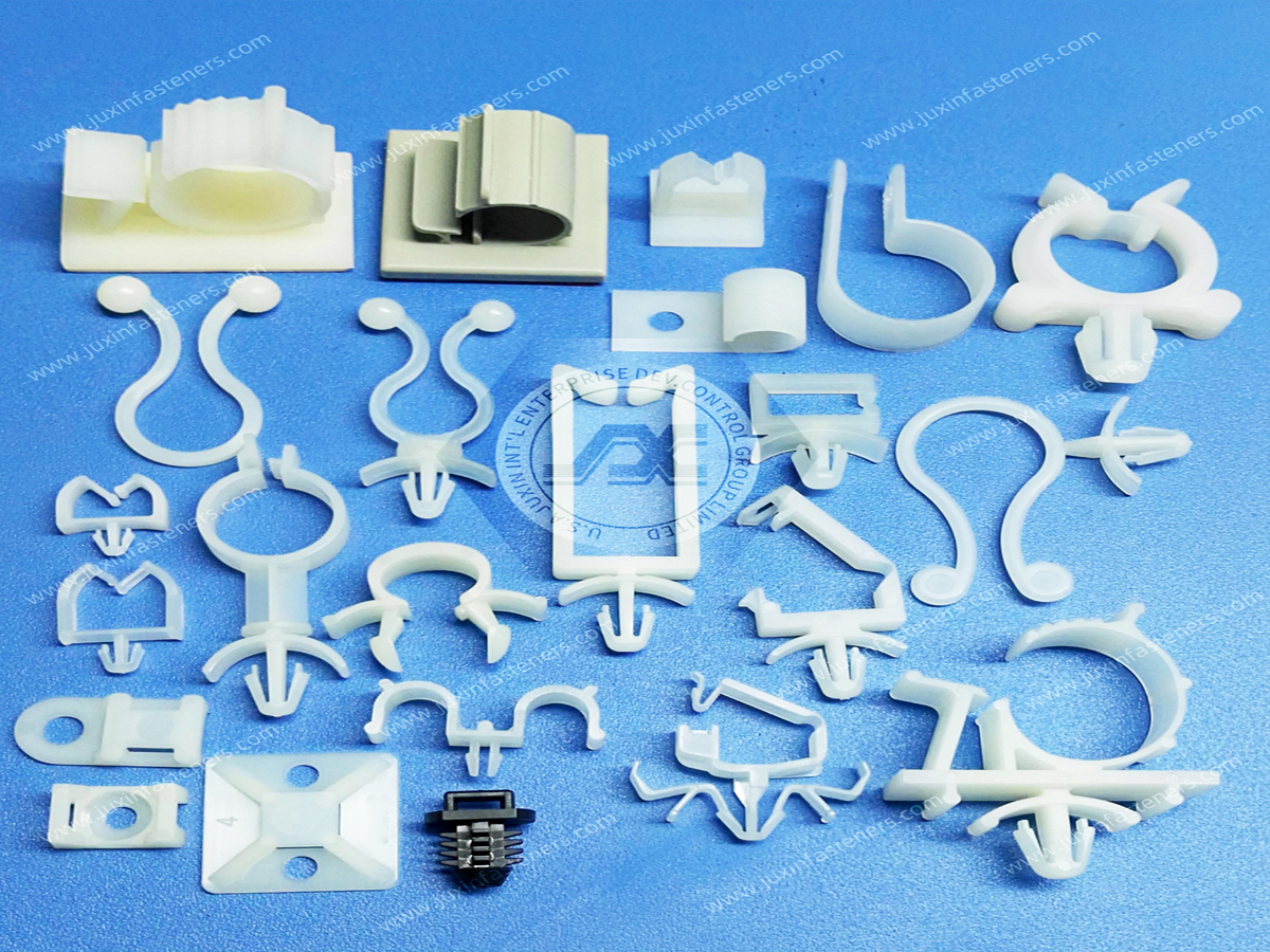
Two bundles with the same diameter can have very different mass.
For example, a bundle containing heavy copper power conductors can impose much greater dynamic load than a lightweight sensor harness of similar diameter.
Therefore:
Bundle Diameter ≠ Dynamic Harness Load
For vibration-sensitive applications, engineers should consider both:
bundle geometry
bundle mass
Harness retention depends on the routing system, not just one clamp.
Spacing between supports affects:
unsupported harness length
sag
movement
dynamic loading
bend control
A heavy cable supported at long intervals behaves differently from the same cable supported more frequently.
There is no universal clamp-spacing value that applies to every harness.
Spacing should follow the cable, environment, vehicle or equipment design, and applicable customer requirements.
A clamp should not force a cable into an unsuitable bend immediately after the retention point.
Routing design should consider:
minimum cable bend radius
connector exit direction
branch points
service loops
moving interfaces
This is especially important for:
high-voltage cables
shielded cables
high-speed data cables
fiber-optic cables
fluid tubing
Cable damage can occur when the harness repeatedly moves against:
clamp edges
chassis surfaces
adjacent cables
nearby hardware
A good routing design therefore considers not only whether the clamp retains the harness, but also:
Where can relative movement occur?
Potential responses can include:
changing clamp position
changing clamp geometry
using smoother contact surfaces
adjusting bundle fit
adding appropriate protective sleeving
Cable-contact surfaces should be evaluated for:
sharp edges
molding flash
gate vestige
rough surfaces
abrupt geometry
Long-term vibration can make seemingly minor contact features important.
The clamp-to-chassis interface can determine the reliability and assembly efficiency of the routing system.
Common approaches can include:
screw mount
push mount
fir tree mount
stud mount
snap mount
custom molded interface
The correct mounting method depends on the host structure.
For push-in designs, panel-hole diameter affects:
insertion
retention
alignment
service removal
An oversized hole can reduce retention.
An undersized hole can increase installation force or prevent complete engagement.
The actual molded fastener geometry and panel tolerance must be reviewed together.
Push-in retention features are often designed around a defined panel-thickness range.
If the panel is too thin or too thick for the clip geometry, the fastener may not seat or retain as intended.
Therefore:
Correct Hole Diameter Alone ≠ Correct Panel Interface
Panel thickness also matters.
A clip installed into molded plastic may behave differently from the same clip installed into sheet metal.
Differences can include:
hole-edge geometry
wall thickness
substrate flexibility
local deformation
insertion behavior
The actual host material should be identified during selection.
Adjustable cable clamps are frequently used in equipment exposed to vibration.
However:
Adjustable Cable Clamp ≠ Certified Vibration Performance
Dynamic behavior depends on:
harness mass
clamp spacing
mounting stiffness
standoff height
clamp material
temperature
vibration direction
frequency
acceleration
surrounding geometry
Critical applications should be validated according to the applicable equipment or customer test requirements.
For ratcheting designs, engineers should evaluate whether the locking geometry remains engaged under the actual dynamic load.
Relevant factors can include:
tooth geometry
pawl geometry
strap stiffness
material
temperature
sustained load
vibration direction
Visual engagement alone does not define long-term performance.
Plastic components exhibit time-dependent mechanical behavior.
If an adjustable clamp remains under sustained deflection, the material can experience creep or stress relaxation.
A simplified relationship is:
Initial Deflection + Time + Temperature + Load → Change in Retention Condition
The significance depends on:
resin
geometry
stress
temperature
moisture
duration
This is why initial clamp tightness alone is not sufficient to predict long-term retention.
PA66 is widely used for molded cable-management components because suitable grades can provide useful combinations of:
strength
toughness
fatigue performance
moldability
electrical properties
However:
PA66 ≠ Automatically the Correct Material for Every Clamp
The actual resin grade must match the operating environment.
Flexible latches and ratchet pawls rely on controlled elastic deflection and recovery.
Their performance depends on:
polymer grade
geometry
strain level
temperature
moisture
cycling
Therefore, “nylon has spring memory” is not a sufficient engineering specification.
The component design and resin must be evaluated together.
Heat-stabilized nylon grades may be considered where elevated-temperature aging is important.
Potential applications include selected areas in:
automotive systems
power electronics
industrial equipment
energy systems
However, the material's actual temperature capability must be based on the specified resin and application conditions.
“Heat stabilized” should not be interpreted as an unlimited high-temperature rating.
Impact-modified polymers may be considered where low-temperature toughness or shock behavior is important.
However, modification can also change:
stiffness
strength
dimensional behavior
Material selection therefore requires trade-off analysis.
Polyamides absorb environmental moisture.
This can affect:
stiffness
toughness
dimensions
latch behavior
ratchet engagement
long-term retention
The significance depends on the actual resin, geometry, humidity, temperature, and application.
Some electrical, server, telecommunications, energy-storage, or power-electronics applications may require specific polymer flammability characteristics.
Where applicable, specify the required material grade and documentation.
A generic nylon clamp should not automatically be described as flame retardant.
Likewise:
Nylon ≠ Automatically UL 94 V-0
The actual resin grade and applicable thickness must be confirmed.
Cable clamps may encounter:
oils
greases
coolants
cleaning chemicals
fuels
process fluids
salt-containing environments
Compatibility should be evaluated using:
Polymer Grade + Chemical + Concentration + Temperature + Exposure Time + Mechanical Stress
A broad “chemical resistant” statement is not sufficient for critical applications.
Plastic cable clamps are non-metallic components and can reduce direct conductive contact at the clamp location.
However:
Plastic Clamp ≠ Complete Electrical Isolation System
Electrical safety depends on the complete architecture.
The clamp does not automatically establish:
creepage distance
clearance distance
dielectric withstand
high-voltage system compliance
These requirements must be evaluated at system level.
EV, energy-storage, power-electronics, and industrial electrification systems may contain high-voltage cable assemblies.
Cable-routing hardware can help maintain physical position and separation.
However, a plastic clamp alone should not be treated as defining the electrical isolation requirement.
High-voltage routing design may need to consider:
cable insulation system
voltage level
creepage and clearance
conductor routing
chassis geometry
thermal environment
applicable equipment requirements
These products should be selected according to function rather than visual similarity.
Use when the bundle requires a defined range of loop adjustment.
Evaluate where the bundle diameter is controlled and a fixed closed-loop clamp is appropriate.
Use where a separate cable tie provides bundle retention and the mount primarily anchors the tie to the structure.
Evaluate where a push-in panel interface is required for a defined harness-retention geometry.
Use where the cable route must be elevated away from the mounting surface.
A simplified decision tree is:
Variable Bundle Size? → Adjustable Cable Clamp
Fixed Bundle Diameter? → Nylon P-Clip
Need Replaceable Tie-Based Retention? → Cable Tie Mount
Need Push-In Panel Mounting? → Fir Tree / Push-Mount Harness Clip
Need Harness Elevation? → Standoff Harness Clip
| Design Condition | Engineering Question | Selection Direction |
|---|---|---|
| Variable bundle diameter | Must one component fit multiple harness configurations? | Evaluate adjustable clamp |
| Fixed bundle diameter | Is repeatable closed-loop sizing preferred? | Evaluate P-clip |
| Serviceable harness | Must the clamp reopen without destruction? | Evaluate releasable design |
| Panel obstruction | Must the harness clear a rib, weld or component? | Define standoff height |
| Heavy power cable | What dynamic load reaches the mounting base? | Review harness mass and standoff moment |
| Push-in assembly | What are panel hole and thickness tolerances? | Match mounting interface |
| High vibration | How far can the unsupported harness move? | Review clamp spacing and system dynamics |
| Sensitive cable | Can clamp compression damage the cable? | Control contact pressure and geometry |
| Thermal cycling | Must the harness move relative to the chassis? | Avoid unnecessary over-constraint |
| High voltage | Is physical routing part of an insulation system? | Perform system-level electrical review |
| Repeated service | How many opening cycles are expected? | Validate latch durability |
| Custom route | Do standard clips miss the required position? | Evaluate custom molded clip |
Automotive cable-management hardware can be used to route selected:
sensor harnesses
body wiring
lighting wiring
control harnesses
power distribution wiring
auxiliary electrical circuits
Automotive applications can introduce:
vibration
thermal cycling
moisture
fluids
tight packaging
high-volume assembly requirements
Clamp selection should therefore consider the full installation environment.
Potential applications include routing selected:
BMS wiring
sensor leads
low-voltage harnesses
high-voltage cable assemblies
thermal-management tubing
auxiliary wiring
The appropriate clip depends on the actual cable, voltage architecture, temperature, vibration environment, and battery-pack design.
Internal links should connect this page with EV Battery Pack Plastic Fasteners.
Adjustable cable clamps may support wiring in:
control cabinets
robotic cells
machine tools
sensors
actuators
vision systems
distributed control equipment
Machine environments can introduce vibration, oil, repeated maintenance, and moving interfaces.
Robotic systems require careful distinction between:
static harness sections
flexing harness sections
A clamp appropriate for a static frame location may not be appropriate for a continuously moving robotic joint.
Routing design must account for the cable manufacturer's flex and bend requirements.
Potential applications include:
inverter cabinets
UPS equipment
switchgear controls
power conversion equipment
auxiliary harnesses
monitoring electronics
Electrical spacing, temperature, cable mass, and flammability requirements should be evaluated at equipment level.
Adjustable clamps and cable holders may support selected internal or rack-level routing of:
power cables
control wiring
fan wiring
sensor leads
structured cabling
Dense server environments make packaging and airflow important.
Cable-management hardware should therefore retain the harness without unnecessarily obstructing cooling paths.
Telecommunications equipment may require organized routing for:
power cables
control wiring
copper interconnects
fiber systems
Cable sensitivity varies significantly between these categories, so clamp geometry should be matched to the actual cable construction.
Potential applications include selected wiring within:
diagnostic equipment
laboratory systems
monitoring equipment
control hardware
Cleaning environment, serviceability, material requirements, and cable sensitivity should be defined by the equipment manufacturer.
Adjustable cable clamps may be used in:
control systems
sensors
fan wiring
compressor-related electrical systems
equipment panels
Temperature, vibration, condensation, and service access can affect selection.
Marine environments may introduce:
humidity
salt exposure
vibration
temperature variation
The actual polymer grade and complete mounting system should be evaluated for the intended environment.
Procurement teams may search for adjustable cable clamps or standoff harness clips because they need to:
replace an existing supplier
qualify a second source
replace a discontinued part
consolidate harness-hardware suppliers
reduce lead-time risk
source a custom routing component
support a new vehicle or equipment platform
A reliable cross-reference should compare more than overall clip appearance.
Depending on the component, compare:
minimum bundle range
maximum bundle range
loop geometry
strap width
contact geometry
standoff height
overall height
mounting interface
panel hole diameter
panel thickness
stud dimensions where applicable
latch type
release method
material
color
installation direction
operating environment
Two clips that look similar may not be functionally interchangeable.
Customers can submit:
current manufacturer
current manufacturer part number
OEM internal part number
physical sample
2D drawing
3D model
panel specifications
harness information
Juxin Fasteners can review the dimensional and functional interfaces to identify a candidate standard product or determine whether custom development should be evaluated.
A physical sample can help review:
bundle interface
ratchet geometry
latch design
standoff height
mounting feature
panel engagement
material characteristics
release mechanism
For critical applications, candidate samples should be validated in the actual or representative harness assembly.
Depending on the project, validation may include:
bundle fit
installation effort
closing force
release function
panel insertion
panel retention
harness movement
vibration testing
thermal cycling
environmental conditioning
repeated service cycles
Testing requirements should follow the customer's equipment requirements.
Standard clips may not satisfy every routing architecture.
Custom molded cable-management components can be evaluated where the application requires:
custom standoff height
custom bundle range
proprietary latch
unusual mounting hole
special push-in interface
integrated anti-rotation feature
multi-bundle routing
special panel geometry
integrated locating feature
Custom molded clips can potentially manage more than one cable route within one component.
For example, separate channels may be used where the assembly requires controlled separation between:
power and signal wiring
parallel harnesses
cable and tubing
However, the required separation must be determined by the equipment design.
A multi-channel plastic clip does not itself establish electrical compliance.
For custom projects, customers can provide:
2D drawing
3D CAD model
harness model
panel model
existing sample
mating-interface dimensions
Critical dimensions may include:
bundle range
standoff height
mounting interface
panel hole
panel thickness
latch geometry
overall envelope
Adjustable clamps rely heavily on flexible molded features.
Custom designs should therefore consider:
allowable deflection
root radius
wall thickness
tooth geometry
draft
undercuts
parting line
gate location
molding shrinkage
material flow
A ratchet mechanism that functions in CAD is not automatically a reliable molded component.
Production-line performance is also important.
Engineering teams may need to consider:
installation force
hand access
tool access
audible or tactile engagement
visibility
assembly orientation
mistake-proofing
A clip that performs well after installation but is difficult to assemble consistently can still create manufacturing problems.
For automated or semi-automated assembly, additional factors can include:
part orientation
gripping surfaces
dimensional repeatability
insertion direction
engagement detection
These requirements should be defined early for high-volume programs.
Depending on the project, procurement teams may request:
material identification
resin information
dimensional inspection
lot identification
lot traceability
RoHS documentation
REACH documentation
flammability information where applicable
customer-specific quality documentation
Requirements should be defined during the RFQ.
For efficient engineering and commercial evaluation, provide as much of the following as available:
existing manufacturer
existing part number
OEM internal part number
physical sample
2D drawing
3D CAD model
cable or harness type
minimum bundle diameter or envelope
maximum bundle diameter or envelope
approximate bundle mass where relevant
cable jacket material where relevant
required standoff height
available installation envelope
mounting interface
panel hole diameter
panel thickness
stud dimensions where applicable
mounting direction
required release function
expected service cycles
clamp spacing where relevant
bend-radius requirement
operating temperature
humidity
chemical exposure
vibration / shock environment
electrical requirements
flammability requirements where applicable
material requirement
color
required documentation
sample quantity
order quantity
estimated annual volume
packaging requirements
For a new harness-routing application:
Harness Geometry → Bundle Mass → Required Route → Required Movement → Clamp Type → Standoff Height
→ Mounting Interface → Environment → Material → Sample → Assembly Validation → Production RFQ
For an adjustable bundle:
Minimum Bundle + Maximum Bundle → Cable Sensitivity → Adjustment Mechanism → Retention Level → Sample → Functional Validation → Production
For a standoff application:
Obstacle Geometry → Required Clearance → Harness Diameter → Standoff Height → Dynamic Load → Mounting Interface → Sample → Validation
For a high-vibration application:
Harness Mass + Unsupported Length + Clamp Spacing + Vibration Direction → Clamp Architecture → Mounting Interface → Prototype → System-Level Validation → Qualification
For a second-source project:
Existing Part / Sample → Bundle Range → Standoff Height → Mounting Interface → Material → Candidate Cross-Reference
→ Sample → Assembly Validation → Supplier Qualification → Production RFQ
For a custom component:
Harness + Chassis CAD → Functional Requirements → DFM Review → Material Selection → Tooling Strategy → Sample → Customer Validation → Production
Adjustable cable clamps should connect internally to related products according to the routing problem.
Related Juxin Fasteners solutions include:
Nylon P-Clips for fixed-diameter cable and tubing retention
Nylon Cable Clips for general wire-routing applications
Cable Tie Mounts for tie-based harness anchoring
Fir Tree Fasteners for push-in panel retention
EV Battery Pack Plastic Fasteners for battery and powertrain cable-management applications
Nylon Snap Bushings for protecting cables passing through panel holes
Strain Relief Bushings for controlling external loads at cable-entry points
Custom Molded Plastic Fasteners for proprietary routing and mounting geometries
The internal engineering path should be:
Variable Bundle Size? → Adjustable Cable Clamp
Fixed Bundle Diameter? → Nylon P-Clip
Need Harness Elevation? → Standoff Harness Clip
Need Tie-Based Retention? → Cable Tie Mount
Need Push-In Panel Retention? → Fir Tree Harness Fastener
Cable Passing Through Sheet Metal? → Nylon Snap Bushing
Cable Entering Enclosure Under Pull / Twist Load? → Strain Relief Bushing
Need Proprietary Geometry? → Custom Molded Plastic Fastener
Juxin Fasteners supplies standard and custom adjustable cable clamps, standoff harness clips, P-clips, wire retainers,
cable tie mounts, fir tree fasteners, panel bushings, strain relief components, and other molded plastic fastening and cable-management hardware for industrial OEM applications.
Engineering, procurement, supplier-development, and supply-chain teams can submit:
existing manufacturer part numbers
OEM internal part numbers
physical samples
2D drawings
3D CAD models
harness dimensions
bundle range
panel specifications
standoff requirements
mounting-interface dimensions
material requirements
operating conditions
estimated annual demand
for technical and commercial evaluation.
For a new adjustable cable-clamp application, the key engineering question is not simply:
“What diameter cable clamp do I need?”
A more useful question is:
“What harness envelope must be controlled, how much movement should be allowed,
how much compression can the cable tolerate, what clearance must the standoff create, and what dynamic loads will reach the clamp and its mounting interface?”
For second-source qualification, matching the nominal bundle diameter alone is not sufficient.
The more reliable sourcing path is:
Bundle Range + Cable Construction + Grip Requirement + Standoff Height + Mounting Interface + Panel Geometry + Harness Mass + Environment + Serviceability + Assembly Validation
This approach creates a clearer path from engineering search and product selection to physical sample evaluation, second-source qualification, custom molded component development, and production sourcing.
Email: info@juxinfasteners.com
Website: www.juxinfasteners.com
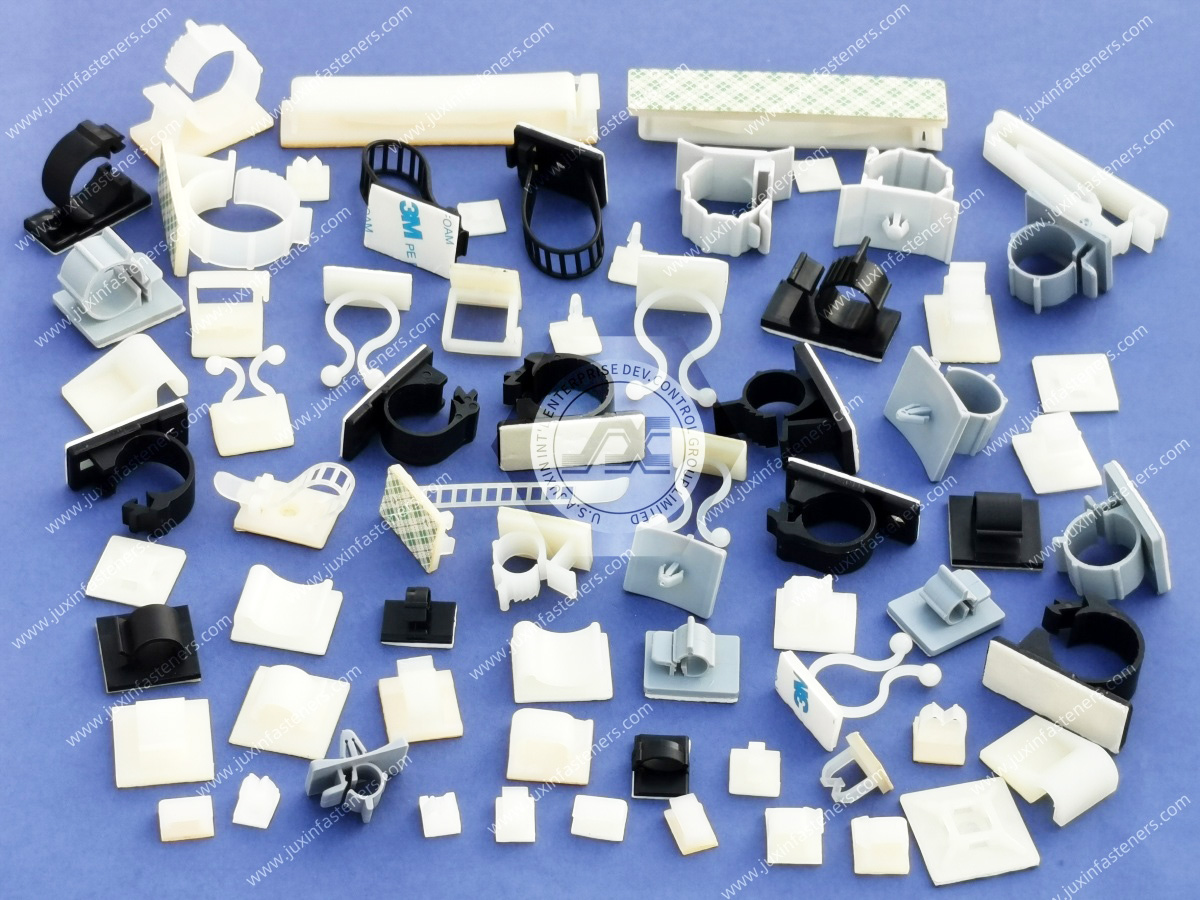
 MORE NEWS

Sep. 27, 2026

Sep. 27, 2026

Sep. 27, 2026
Contact Us
Tel.:
+86 020 8621 0320
+86 020 3121 6067
E-mail:
Technical Support:
Navigation
SEND INQUIREY