
Call Us
+86 136 6007 9809
Call Us
+86 136 6007 9809

Sep. 27, 2026
Edge-locking PCB supports, bayonet board retainers, slide-in PCB supports,
and plastic card guides provide specialized mechanical support for printed circuit boards installed in electronic enclosures, server chassis,
telecommunications equipment, industrial controls, transportation electronics, instrumentation,
and other equipment where simple point-mounted PCB supports may not provide the required board guidance or retention architecture.
Unlike conventional PCB standoffs that primarily establish vertical spacing at discrete mounting holes,
edge-support systems interact with the perimeter of the printed circuit board. Depending on the design, they can guide the PCB during insertion, control lateral movement,
support the board edge, provide snap retention, assist chassis alignment, or enable service removal without conventional threaded hardware at every mounting point.
These functions become especially important where equipment is exposed to vibration, mechanical shock, repeated service cycles, dense packaging,
or thermal expansion between the PCB and surrounding chassis.
However, the presence of an edge lock, bayonet feature, snap latch, or card guide does not by itself establish a specific vibration or shock capability.
Performance depends on the complete system:
PCB + Support Geometry + Chassis Interface + Material + Retention Direction + Mounting Pattern + Temperature + Vibration / Shock Environment
Juxin Fasteners supplies standard and custom PCB supports, edge-locking board retainers, bayonet-style supports, snap-fit PCB supports, nylon standoffs,
plastic spacers, card guides, cable-management hardware, and drawing-based custom molded plastic components for industrial OEM applications.
Engineering and procurement teams can submit existing manufacturer part numbers, physical samples, PCB thickness, chassis cutout dimensions,
2D drawings, 3D CAD models, material requirements, or application conditions for technical and commercial evaluation.
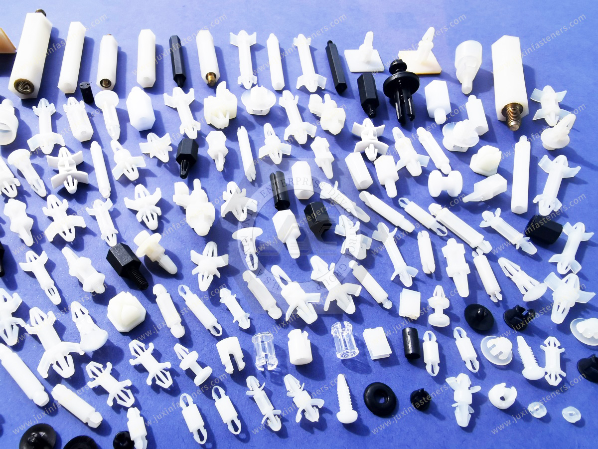
An edge-locking PCB support is a mechanical component designed to engage a printed circuit board at or near its perimeter rather than relying exclusively on a screw hole through the PCB.
Depending on the geometry, the support may provide one or more functions:
PCB edge guidance
lateral positioning
vertical support
snap retention
anti-rattle control
chassis location
insertion guidance
extraction or release capability
A simplified architecture may be:
Chassis / Rail → PCB Edge Support → PCB
rather than:
Screw → PCB Hole → Spacer / Standoff → Chassis
This difference changes the load path and assembly behavior.
Edge supports and conventional standoffs should not automatically be treated as interchangeable.
A standoff normally supports a PCB at a defined point and establishes board-to-chassis spacing.
Depending on its design, it may use:
threads
snap-fit features
push-in retention
screw mounting
An edge support interacts with the perimeter of the board and can guide or restrain movement along selected directions.
A card guide typically provides a channel or rail along which a PCB or card slides during installation or removal.
A board retainer primarily prevents unwanted board movement or disengagement.
One component can combine several of these functions, but the engineering role should be identified before a replacement is selected.
PCB edge-support hardware is available in multiple architectures.
The correct design depends on:
board geometry
board thickness
chassis architecture
direction of assembly
required movement
retention direction
service requirements
Edge-locking PCB supports typically incorporate a slot, channel, hook, barb, or flexible latch that engages the board edge.
Depending on the design, the component may:
locate the board
prevent lateral displacement
reduce edge movement
retain the PCB after insertion
allow intentional release for service
The locking feature must be evaluated against the actual board thickness and edge geometry.
Bayonet-style components use a keyed, twist-lock, slot-engagement, or similar mechanical interface to engage the support with a chassis or mounting feature.
The term “bayonet” can describe different commercial geometries.
Therefore:
Bayonet PCB Support ≠ One Universal Geometry
Cross-referencing should be based on the actual mating interface rather than the product name alone.
Slide-in PCB supports guide the board along a defined path during assembly.
Potential advantages include:
repeatable insertion
reduced board misalignment
simplified service access
controlled card position
However, the guide must provide adequate clearance to avoid excessive friction or board damage.
Snap-lock retainers use flexible polymer features to capture the PCB after it reaches the intended position.
The latch geometry influences:
insertion force
retention force
extraction method
serviceability
cycle life
Multiple flexible contact features can distribute retention across more than one contact point.
Depending on the design, this may help control:
board flutter
local movement
alignment
However, additional contact does not automatically mean greater system reliability.
The resulting load on the PCB edge must still be evaluated.
A PCB can potentially move in multiple directions.
These include:
vertical movement
lateral movement
longitudinal sliding
rotation
out-of-plane flexure
An edge support may control one direction strongly while permitting movement in another.
Therefore, engineers should first ask:
Which degree of freedom actually needs to be controlled?
A component selected only because it “locks the PCB” may provide retention in the wrong direction for the actual load case.
If equipment experiences vibration or shock, the direction of the mechanical load relative to the support geometry matters.
A support designed primarily to prevent lateral sliding may behave differently under:
vertical pull
board bending
torsional loading
longitudinal acceleration
This is why retention-force values, where required, should be interpreted in the correct loading direction.
The slot or channel of an edge-locking support must be compatible with the actual PCB thickness.
A nominal board thickness such as 1.6 mm is common in many electronic assemblies, but it is not universal.
Printed circuit boards may use different thicknesses depending on:
electrical design
layer count
mechanical stiffness
connector requirements
application
Therefore:
“PCB Support for 1.6 mm Board” ≠ Universal PCB Support
The actual board specification should be confirmed.
The board itself has manufacturing tolerance.
The support also has molding tolerance.
The functional fit therefore depends on:
PCB Thickness Range + Support Slot Range + Environmental Dimensional Change
If the fit is too tight, potential issues include:
high insertion force
board-edge abrasion
difficult service removal
induced board stress
If the fit is too loose, potential issues include:
rattle
edge movement
reduced positioning accuracy
impact between PCB and guide surfaces
A board-guide interface can also depend on:
lead-in geometry
channel depth
contact length
latch position
board-edge finish
nearby copper or components
chassis alignment
Therefore, nominal slot width alone is not sufficient for critical cross-referencing.
A useful design consideration is the relationship between the support and the PCB edge layout.
Mechanical retention features should not interfere with:
copper traces
edge connectors
surface-mounted components
test points
solder joints
conformal coating requirements
Where an edge support contacts the PCB, the mechanical keep-out zone should be considered during board layout.
A PCB support must interface correctly with both:
the circuit board, and
the enclosure or chassis.
Chassis interfaces can include:
round holes
rectangular slots
keyed cutouts
rails
sheet-metal edges
molded housing features
twist-lock openings
A correct PCB-side fit with an incorrect chassis interface still produces an unusable component.
Where a support snaps into sheet metal or another panel, panel thickness may directly affect retention.
Where it mounts into a rail, the rail geometry can affect:
position
insertion
locking
extraction
lateral movement
The complete interface should therefore be reviewed.
Multiple PCB supports installed along a large board create a mounting array.
The relative position of those supports matters.
If chassis holes or rails are misaligned, forcing the PCB into place can introduce mechanical stress.
Potential consequences include:
PCB bow
connector misalignment
local edge stress
difficult insertion
difficult service removal
For large boards, tolerance accumulation across the complete mounting pattern should be evaluated.
A common assumption is that the tightest possible board retention produces the most reliable assembly.
That is not always true.
Electronic assemblies experience dimensional change with temperature.
The PCB and chassis may expand at different rates.
If every edge of a large PCB is rigidly constrained, thermal movement can create unwanted mechanical stress.
Therefore:
Maximum Constraint ≠ Automatically Maximum Reliability
A more appropriate architecture may use:
Fixed Location + Guided Support + Controlled Movement
rather than rigidly locking every degree of freedom.
For some large-board assemblies, designers may establish a primary locating region while allowing controlled movement elsewhere.
Conceptually:
Primary Location → Defines Board Position
Secondary Guides → Support Board but Allow Necessary Thermal Movement
This approach can help prevent over-constraint.
Whether it is appropriate depends on the actual assembly and loading environment.
Printed circuit boards, steel chassis, aluminum chassis, and polymer supports do not necessarily expand at the same rate.
During thermal cycling, this difference can change:
guide clearance
board position
latch loading
connector alignment
local stress
The effect becomes more important as:
board dimensions increase
temperature range increases
constraints increase
In many electronic assemblies, PCB position is also controlled by connectors.
Examples include:
backplane connectors
card-edge connectors
high-speed interconnects
power connectors
The support system should not force the PCB into a position that conflicts with the connector's intended alignment.
Mechanical support and electrical interconnect geometry should be reviewed together.
Edge-locking PCB supports are often used in equipment exposed to vibration or shock.
However:
Edge-Locking Support ≠ Certified High-Vibration Performance
Actual performance depends on:
PCB mass
PCB dimensions
component mass distribution
support spacing
support geometry
chassis stiffness
vibration direction
frequency
acceleration
shock pulse
temperature
material condition
Applications requiring defined vibration or shock performance should be validated using the relevant equipment-level test requirements.
A lightly populated PCB and a board carrying large:
heat sinks
transformers
power modules
GPU assemblies
connectors
can impose very different dynamic loads on the support system.
Therefore, PCB dimensions alone do not define the vibration requirement.
A circuit board can behave as a flexible structure.
Its vibration response depends on factors including:
board size
thickness
mounting spacing
component mass
support locations
Edge supports can influence the board's boundary conditions and therefore its dynamic response.
They should be treated as part of the mechanical system rather than as isolated accessories.
Material selection should consider:
Retention Geometry → Flex Requirement → Temperature → Environment → Electrical Requirement → Flammability Requirement → Service Cycles → Manufacturing
PA66 is widely used for molded electronic fastening and support components because appropriate grades can provide useful combinations of:
strength
toughness
fatigue performance
moldability
electrical properties
However:
PA66 ≠ Automatically Correct for Every PCB Support
The actual resin grade and operating environment should be specified.
A snap latch or locking finger needs sufficient flexibility to deflect during installation without cracking.
It also needs adequate recovery after insertion.
Therefore, the best material is not necessarily the material with the highest stiffness.
Design must balance:
stiffness
toughness
fatigue
deflection
geometry
temperature
Glass-filled nylon can provide increased stiffness and altered dimensional behavior compared with unfilled nylon.
However, reinforcement can also affect:
flexibility
impact response
anisotropy
molding shrinkage
warpage
latch behavior
For flexible snap arms, increased stiffness may not always be desirable.
Therefore:
Glass-Filled Nylon ≠ Automatically Better PCB Retainer Material
The latch geometry and required deflection should be reviewed.
Polyamides absorb moisture.
Conditioning can affect:
stiffness
toughness
dimensions
snap behavior
fatigue response
For precision edge channels, moisture-related dimensional behavior should be considered together with PCB-thickness tolerance.
A molded nylon support can behave differently in a dry-as-molded condition than after environmental conditioning.
This can matter when:
insertion force is tightly controlled
latch deflection is high
channel clearance is small
dimensional tolerances are tight
Sample evaluation should therefore represent the intended application as closely as practical.
Some server, telecommunications, electrical, and electronic equipment requires specific polymer flammability characteristics.
Where applicable, the customer should specify the required resin and documentation.
UL 94 classifications apply to specific materials under defined test conditions and thicknesses.
Therefore:
PA66 ≠ Automatically UL 94 V-0
and
PCB Support Geometry ≠ Automatically Certified by the Resin Rating Alone
The actual resin grade and equipment requirements must be confirmed.
Polymer PCB supports can provide non-conductive physical support.
However, their presence does not automatically establish compliance with electrical insulation requirements.
Creepage and clearance depend on the complete geometry and electrical system.
Relevant factors can include:
working voltage
conductive surfaces
contamination
material group
spacing
equipment standard
Therefore:
Plastic PCB Support ≠ Complete Dielectric Design
The equipment designer remains responsible for system-level electrical safety requirements.
These two parameters should not be confused.
Insertion Force describes the effort required to install the PCB or support.
Retention Force describes resistance to unintended disengagement under a defined loading direction.
A useful component balances both.
Very low insertion force with insufficient retention can create reliability problems.
Excessive retention can make service difficult or damage the board during removal.
For serviceable equipment, extraction behavior is an important engineering requirement.
Examples include:
server hardware
telecommunications equipment
test instruments
industrial controllers
modular electronics
A board retainer may require:
release tab
squeeze release
tool access
controlled pull direction
The service procedure should be considered during product selection.
If the PCB is expected to be removed repeatedly, flexible locking features experience cyclic deformation.
Potential long-term considerations include:
fatigue
permanent set
latch wear
reduced retention
accidental breakage
A component suitable for one-time factory assembly may not automatically be suitable for repeated field service.
Snap-fit and slide-in PCB supports can reduce dependence on threaded hardware in selected assemblies.
Potential manufacturing benefits may include:
fewer loose parts
shorter assembly sequence
simplified operator handling
reduced tool access requirements
However, tool-free installation should not be pursued at the expense of:
retention
serviceability
alignment
environmental performance
These products should be separated by function.
Evaluate when the board edge must be located or retained.
Evaluate when discrete PCB mounting holes can be used for tool-efficient board support.
Evaluate when a defined board-to-chassis distance and point-mount architecture are required.
Evaluate where a separate screw passes through the spacing component.
Evaluate when the PCB must slide along a controlled insertion path.
A simplified decision path is:
Need PCB Edge Guidance? → Card Guide / Edge Support
Need Edge Retention After Insertion? → Edge-Locking Board Retainer
Need Snap Mounting Through PCB Hole? → Snap-Fit PCB Support
Need Defined Point Spacing? → PCB Standoff
Need Pass-Through Screw + Controlled Distance? → Unthreaded Spacer
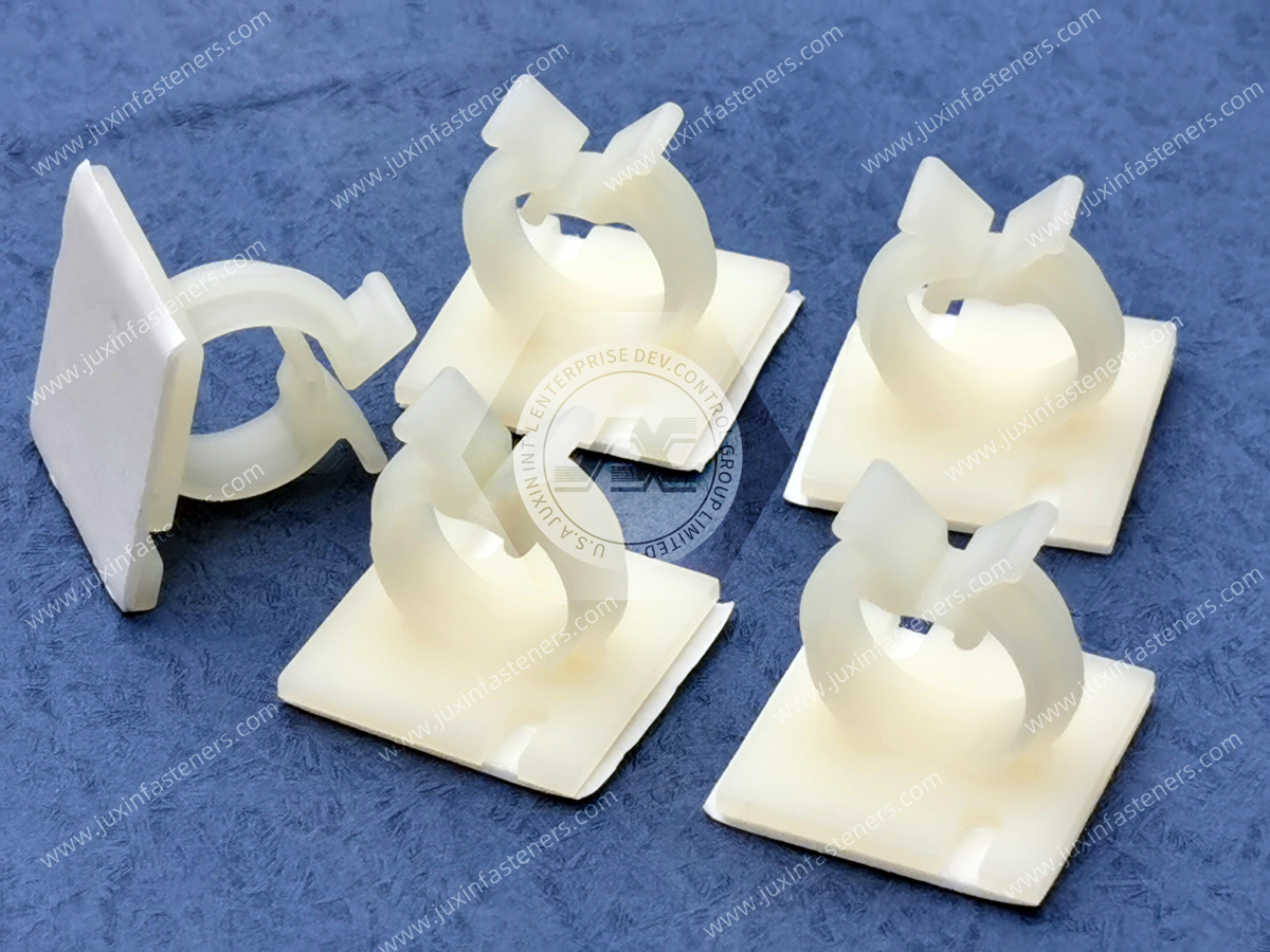
| Design Condition | Engineering Question | Selection Direction |
|---|---|---|
| Sliding PCB | Does the board need an insertion path? | Evaluate card guide or slide-in support |
| Edge retention | Must the board resist lateral disengagement? | Evaluate edge-locking support |
| High vibration | What loads reach the PCB and in which direction? | Validate complete board-support system |
| Thermal cycling | Does the board require controlled movement? | Avoid unnecessary over-constraint |
| Thick or thin PCB | What is the actual board thickness range? | Match guide channel to board specification |
| Large PCB | Can mounting-array tolerance induce bow? | Review multi-point alignment |
| Heavy components | How does PCB mass distribution affect dynamics? | Review support spacing and vibration behavior |
| Field service | How often will the board be removed? | Review release mechanism and cycle durability |
| Electrical spacing | Does support geometry affect creepage or clearance? | Perform system-level electrical review |
| Flame requirement | Is a specific resin classification required? | Specify documented resin grade |
| Existing part replacement | Is nominal appearance enough to cross-reference? | Compare complete board and chassis interfaces |
| Custom chassis | Are standard support geometries unsuitable? | Drawing-based custom component review |
AI servers and high-performance computing platforms may contain:
GPU baseboards
accelerator cards
networking cards
power-distribution boards
control boards
storage modules
high-speed interconnects
PCB mounting hardware in these systems may need to coexist with:
high airflow
dense cabling
large heat sinks
liquid-cooling hardware
high-speed fans
frequent service requirements
Low-profile and serviceable board-retention hardware can therefore become important to chassis architecture.
High-speed cooling fans can introduce continuous mechanical excitation.
However, the response of the PCB depends on the complete structure.
Support selection should therefore consider:
board dimensions
board mass
support positions
chassis stiffness
fan location
actual equipment vibration environment
Telecommunications equipment often uses modular PCB and card architectures.
Potential applications include:
switching equipment
networking hardware
communication modules
rack systems
control cards
Slide-in card guides and board retainers can support controlled installation and service access.
Industrial controls may experience:
machinery vibration
temperature variation
oils
dust
repeated maintenance
PCB-support material and geometry should be evaluated against the actual enclosure environment.
Transportation electronics may be exposed to mechanical shock and vibration.
PCB supports can contribute to board positioning and retention, but equipment-level performance must be validated against the applicable project requirements.
A generic plastic edge support should not be described as automatically compliant with a transportation vibration standard.
Selected non-flight-critical electronic equipment may use polymer PCB mounting hardware where permitted by the equipment design.
Material, flammability, environmental, vibration, documentation, and qualification requirements are application-specific.
No generic PCB support should be assumed to satisfy aerospace requirements solely because of its material or geometry.
PCB supports may be used in:
diagnostic equipment
monitoring systems
laboratory instruments
control electronics
Relevant considerations can include:
serviceability
equipment temperature
cleaning environment
material requirements
dimensional stability
Instrumentation frequently requires modular electronics and repeated service access.
Edge guides and removable PCB retainers can support:
repeatable card insertion
controlled board alignment
maintenance access
where compatible with the instrument architecture.
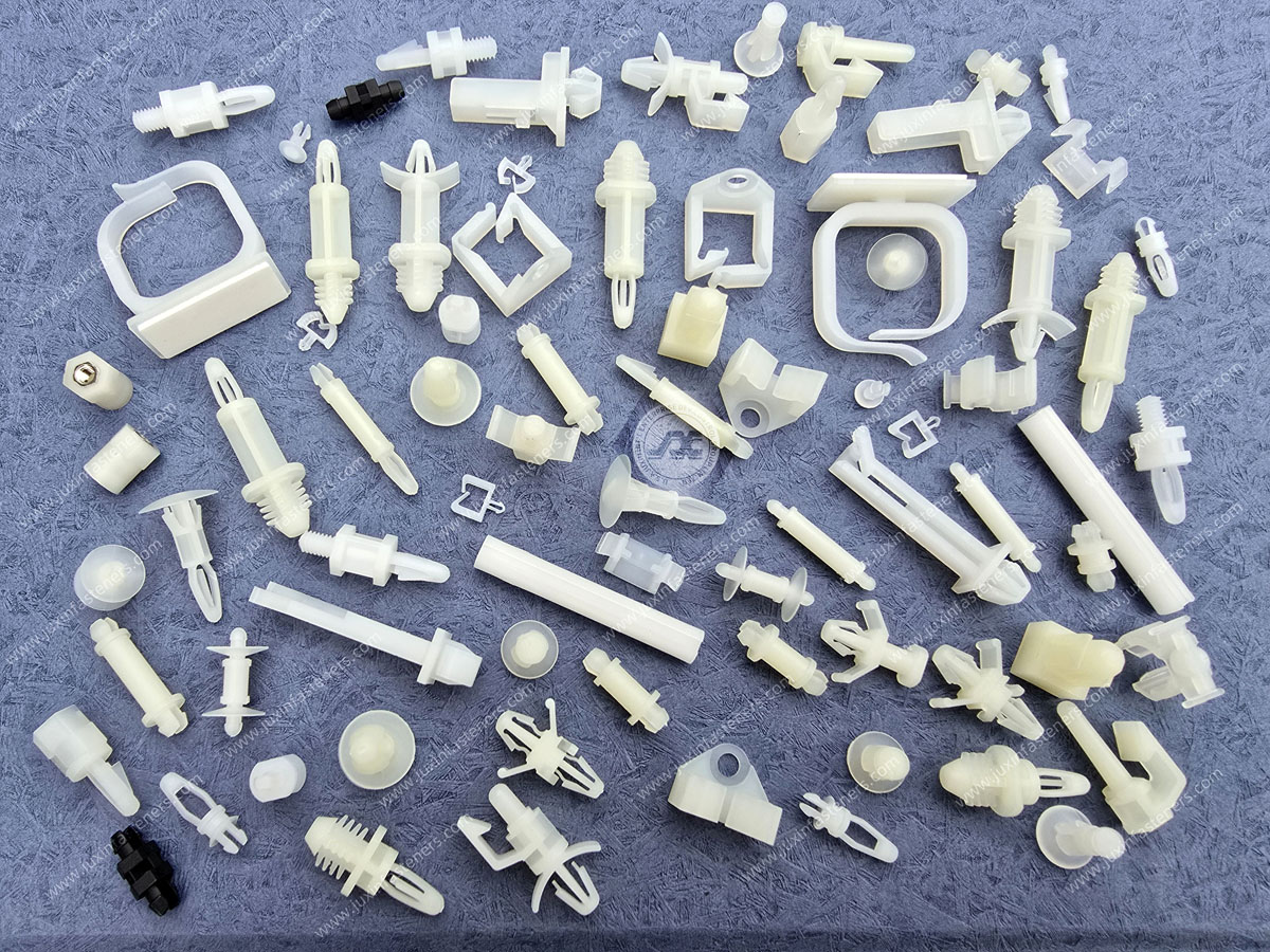
Semiconductor manufacturing and test systems may use specialized PCB and electronics mounting components.
Requirements may include:
dimensional stability
material restrictions
cleanliness
chemical compatibility
thermal behavior
Customer equipment specifications should govern component selection.
Control and auxiliary PCBs in:
power conversion equipment
UPS systems
power distribution equipment
inverter systems
energy storage equipment
may use polymer supports where appropriate.
Electrical spacing, temperature, flammability, and service requirements should be reviewed at system level.
Procurement teams may search for PCB supports because they need to:
replace an existing supplier
qualify a second source
replace a discontinued component
reduce lead-time risk
source an obsolete card guide
consolidate plastic hardware suppliers
develop a custom support for a new chassis
A reliable cross-reference should compare more than overall appearance.
Depending on the component, compare:
PCB thickness range
board slot width
channel depth
edge engagement
latch geometry
support height
chassis mounting interface
panel thickness
mounting hole or slot dimensions
overall dimensions
material
color
insertion direction
retention direction
release method
operating environment
Two PCB supports that look nearly identical can have different functional interfaces.
Customers can submit:
manufacturer name
manufacturer part number
OEM internal part number
physical sample
technical drawing
PCB thickness
chassis drawing
Juxin Fasteners can review the dimensional and functional interfaces to determine whether a standard candidate or custom component should be evaluated.
A physical sample can help identify:
locking geometry
channel dimensions
material characteristics
chassis engagement
release mechanism
critical molded features
However, sample duplication should still be verified against the actual assembly requirements.
Depending on the application, validation may include:
PCB insertion
PCB extraction
latch engagement
board fit
chassis fit
board movement
service release
vibration testing
thermal cycling
environmental conditioning
The validation plan should follow the customer's equipment requirements.
Standard PCB supports may not fit:
proprietary chassis rails
unusual PCB thicknesses
special mounting slots
unique retention directions
compact server architectures
non-standard service mechanisms
Custom molded components may incorporate:
edge channels
snap latches
bayonet features
mounting barbs
locating pins
integrated spacers
cable-routing features
anti-rotation geometry
For custom projects, customers can provide:
2D engineering drawing
3D CAD model
PCB model
chassis model
existing physical sample
mating-interface dimensions
Critical requirements should identify:
board thickness
board engagement
chassis interface
support height
retention direction
required movement
material
operating environment
Custom snap and edge-retention features require DFM review.
Important considerations can include:
latch thickness
root radius
deflection
draft
undercuts
parting line
gate location
material flow
molding shrinkage
A retention feature that works in CAD is not automatically a reliable injection-molded latch.
Depending on the project, procurement teams may request:
material identification
resin information
dimensional inspection
lot identification
lot traceability
RoHS documentation
REACH documentation
flammability information where applicable
customer-specific quality records
Requirements should be defined during the RFQ.
For efficient technical and commercial evaluation, provide as much of the following as available:
existing manufacturer
existing part number
OEM internal part number
2D drawing
3D CAD model
physical sample
PCB thickness
PCB thickness tolerance
PCB edge geometry
board dimensions
approximate board mass
major component mass where relevant
chassis mounting interface
chassis hole / slot dimensions
panel thickness
support height
required retention direction
insertion direction
service removal requirements
expected service cycles
material requirement
color
operating temperature
humidity
chemical exposure
vibration / shock requirements
electrical requirements
flammability requirements where applicable
compliance documentation
sample quantity
production quantity
estimated annual volume
packaging requirements
For a new PCB support application:
PCB Geometry → Board Thickness → Required Degrees of Restraint → Chassis Interface → Thermal Movement → Vibration / Shock → Serviceability → Material → Sample → System Validation → Production RFQ
For a high-vibration application:
Board Mass + Support Pattern + Load Direction → Retention Architecture → Material / Geometry → Prototype → Equipment-Level Vibration Validation → Qualification → Production
For a serviceable card:
Insertion Path → Guide Geometry → Locking Point → Release Method → Cycle Requirement → Sample → Service Evaluation → Production
For a second-source project:
Existing Part Number / Sample → PCB Interface → Chassis Interface → Material → Candidate Cross-Reference → Sample → Assembly Validation → Supplier Qualification → Production RFQ
For a custom component:
PCB + Chassis CAD → Functional Requirements → DFM Review → Material Review → Tooling Strategy → Sample → Customer Validation → Production
Edge-locking PCB supports should connect internally to related products according to the assembly requirement.
Related Juxin Fasteners solutions include:
Snap-Fit PCB Supports for tool-efficient point mounting through PCB holes
Nylon PCB Standoffs for controlled board-to-chassis spacing
Unthreaded Nylon Spacers for pass-through screw assemblies
Nylon Machine Screws for selected non-metallic fastening systems
Cable Tie Mounts for internal wire and harness routing
Nylon P-Clips for cable-bundle retention
Custom Molded Plastic Fasteners for proprietary chassis and board interfaces
AI Server Plastic Hardware for high-density computing and server chassis applications
The internal engineering path should be:
Need Edge Guidance? → PCB Card Guide
Need Edge Locking? → Edge-Locking PCB Support
Need Snap-In Point Mounting? → Snap-Fit PCB Support
Need Defined Board Height? → PCB Standoff
Need Pass-Through Screw Spacing? → Unthreaded Nylon Spacer
Need Internal Harness Routing? → Cable Tie Mount / Nylon P-Clip
Need Proprietary Geometry? → Custom Molded Plastic Fasteners
Juxin Fasteners supplies standard and custom edge-locking PCB supports, bayonet board retainers, card guides, snap-fit PCB supports, nylon standoffs, plastic spacers, cable-management components, and custom molded plastic hardware for industrial OEM applications.
Engineering, procurement, supplier-development, and supply-chain teams can submit:
existing manufacturer part numbers
OEM internal part numbers
physical samples
2D drawings
3D CAD models
PCB thickness
chassis interface dimensions
retention requirements
material requirements
operating environment
annual demand
for technical and commercial evaluation.
For a new PCB-retention application, the engineering question should not simply be:
“Which PCB support fits my board thickness?”
A more useful question is:
“Which directions must the PCB be restrained, which directions should remain free to accommodate assembly and thermal movement,
and how do the PCB, chassis, support geometry, material, vibration environment, and service requirements interact?”
For second-source qualification, visual similarity is not sufficient.
The more reliable sourcing path is:
PCB Interface + Chassis Interface + Retention Direction + Support Height + Material + Thermal Movement + Serviceability + Environmental Requirements + Assembly Validation
This approach provides a clearer path from engineering search and component selection to physical sample evaluation, second-source qualification, custom development, and production sourcing.
Email: info@juxinfasteners.com
Website: www.juxinfasteners.com
 MORE NEWS

Sep. 27, 2026

Sep. 27, 2026

Sep. 27, 2026
Contact Us
Tel.:
+86 020 8621 0320
+86 020 3121 6067
E-mail:
Technical Support:
Navigation
SEND INQUIREY