
Call Us
+86 136 6007 9809
Call Us
+86 136 6007 9809

Sep. 30, 2026
Electric vehicle battery packs and battery energy storage systems combine structural, electrical, thermal, environmental,
and manufacturing requirements within a compact enclosure. The fasteners used throughout these assemblies therefore cannot be selected only by thread size or nominal strength.
A battery enclosure may include thin steel or aluminum panels, perimeter frames, internal module supports, crossmembers, covers, brackets,
cable-management hardware, electrical components, thermal-management interfaces, and serviceable access points. Each location creates a different fastening problem.
For design engineers, the central question is not simply, “Which fastener is strongest?” It is:
Which fastening method creates the required attachment point without introducing unacceptable distortion, corrosion risk, sealing problems, installation constraints, or serviceability issues?
For procurement and supplier-development teams, another question follows:
Can a production fastener be reliably reproduced or second-sourced based on its actual dimensional, material, coating, installation, and functional requirements?
JUXIN FASTENERS supports standard and drawing-based industrial fasteners for OEM applications, including projection weld studs, weld nuts, rivet nuts, clinch fasteners,
threaded inserts, and related fastening components used in sheet-metal and enclosure assemblies.
Battery enclosures place several engineering requirements into the same assembly.
Depending on the enclosure architecture and fastener location, designers may need to manage:
thin-sheet attachment;
aluminum or steel substrate materials;
limited backside access;
vibration and cyclic loading;
mixed-material corrosion;
thermal expansion differences;
assembly automation;
dimensional stack-up;
electrical isolation requirements;
environmental sealing around enclosure boundaries;
service access;
removable covers;
repeatable production installation.
These requirements often conflict.
For example, reducing sheet thickness helps lower enclosure mass, but it also reduces available thread engagement for directly tapped holes.
Welding can create a permanent threaded attachment point, but thermal input may be undesirable for certain materials, coatings, geometries,
or manufacturing sequences. Blind fastening solves an access problem but introduces different hole, grip-range, installation, and sealing considerations.
The correct solution therefore begins with the joint architecture, not with a preferred fastener type.
A battery enclosure should not be treated as one uniform fastening application. Different zones can require different fastening strategies.
Typical fastening locations can include:
Internal brackets may support electrical components, control hardware, cable-routing components, thermal-system hardware, shields, or other auxiliary assemblies.
Depending on the substrate and assembly process, threaded attachment points may be created using weld nuts, weld studs, clinch fasteners, rivet nuts, or other threaded inserts.
Where fasteners participate in load-carrying joints, engineers must consider the complete load path rather than selecting hardware solely from nominal fastener strength.
The substrate, edge distance, sheet thickness, joint geometry, clamp load, bearing area, mating component, installation method, and cyclic loading can all affect joint performance.
Removable covers introduce a different problem.
The fastener may need to provide repeatable clamp load while the sealing system manages environmental ingress.
Engineers should evaluate the relationship among the fastener pattern, flange stiffness, gasket compression, surface flatness, installation sequence, and service requirements.
Not every fastener inside a battery enclosure is structural. Cable clamps, plastic hardware, clips, spacers,
and other secondary fastening components may be used where appropriate for routing, separation, retention, or electrical-isolation functions.
These components should be selected according to the actual mechanical, temperature, chemical, electrical, and environmental requirements of the application.
There is no single universal “battery enclosure fastener.” The appropriate technology depends on substrate material, joint location, production sequence, access, and functional requirements.
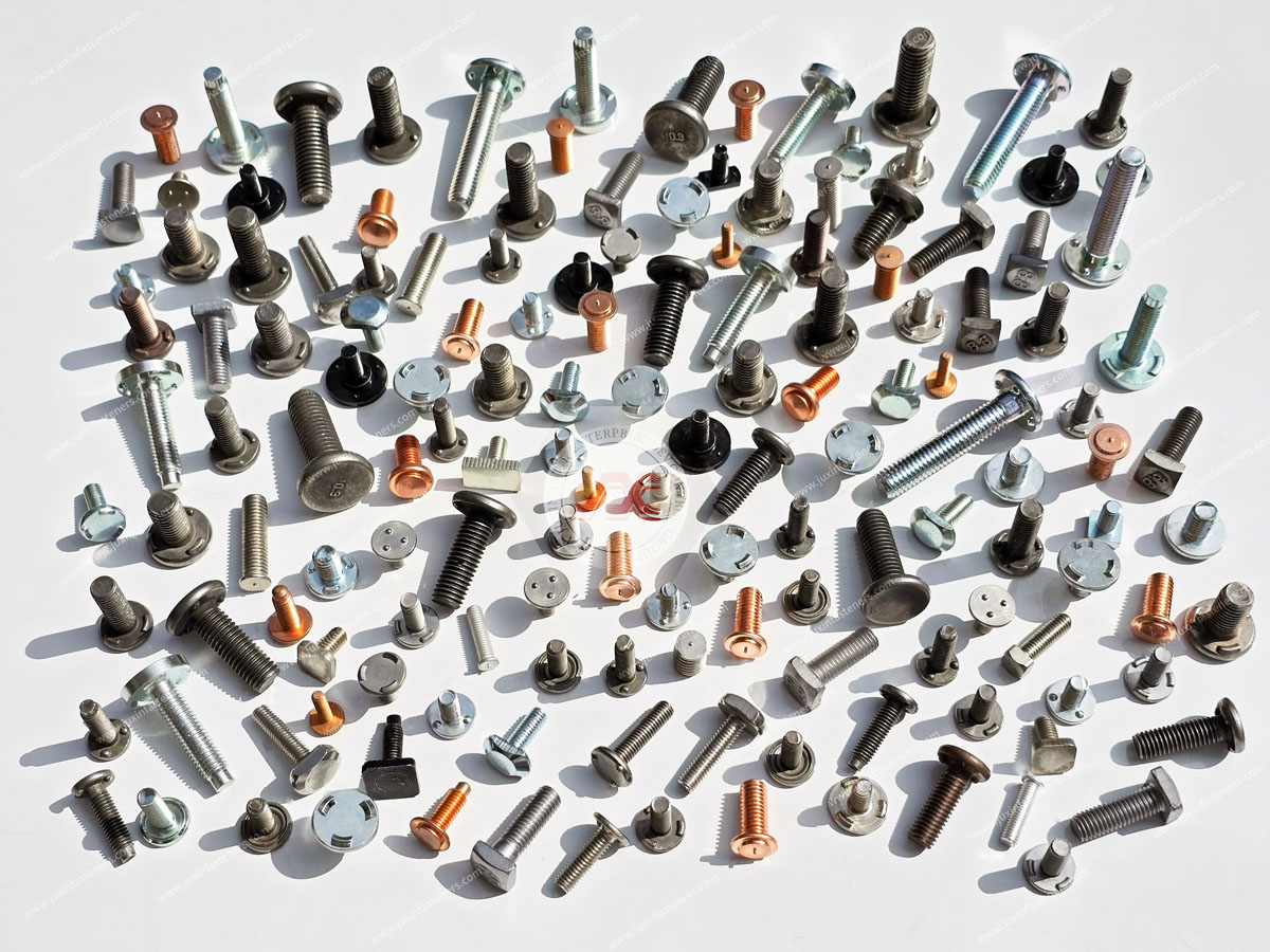
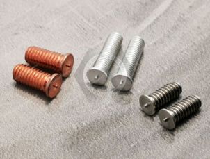
Projection weld studs create a permanently attached threaded stud on a suitable weldable substrate.
They can be useful where an assembly requires:
a fixed male threaded attachment point;
repeatable fastener positioning;
reduced loose-hardware handling;
integration with production welding operations;
attachment before downstream assembly.
For steel enclosure components, resistance-welded studs can provide an efficient production solution when the material,
sheet thickness, projection geometry, welding parameters, coating condition, and required joint performance are compatible.
However, a weld stud should not be selected merely because welding is available.
Engineers should evaluate:
base-material weldability;
sheet thickness;
projection geometry;
required torque and push-out performance;
surface condition;
coating before and after welding;
local distortion;
weld accessibility;
production fixture design;
downstream corrosion protection.
Aluminum requires particular attention. Welding behavior, material combinations, surface oxide,
heat input, and process control differ substantially from conventional resistance welding of low-carbon steel.
A fastener and welding process suitable for a steel battery enclosure should therefore not automatically be transferred to an aluminum enclosure.
Projection weld nuts provide female threads attached directly to suitable sheet-metal structures.
They can be valuable where the assembly requires a permanent threaded feature without relying on threads formed directly in thin sheet.
Typical engineering considerations include:
nut geometry;
projection design;
sheet thickness;
parent material;
welding parameters;
thread protection during welding;
positional tolerance;
torque resistance;
push-out resistance;
coating strategy;
access for the welding process.
For high-volume manufacturing, the interaction among the nut, sheet, welding equipment, fixture, and production sequence is as important as the nominal nut specification.
Clinch nuts, studs, and related self-clinching fasteners create mechanical attachment features by displacing sheet material into the fastener's retention geometry during press installation.
They can be attractive when:
welding heat is undesirable;
the substrate is suitable for clinching;
a press operation can be integrated into manufacturing;
a permanent captive threaded feature is required.
The critical design question is whether the panel can properly support the clinching process.
Important variables include:
sheet material;
sheet hardness;
sheet thickness;
mounting-hole diameter;
hole quality;
edge distance;
installation force;
fastener orientation;
surrounding geometry.
A visually similar clinch fastener with a different undercut, shank, or installation requirement may perform very differently in the same panel.
This is particularly important during second-source qualification.
Rivet nuts are useful when a threaded attachment point must be installed from one side of a panel.
This makes them relevant to battery enclosure zones where backside access becomes restricted by the manufacturing sequence or completed assembly.
A rivet nut can provide a reusable internal thread in relatively thin material, but successful application depends on more than matching the thread size.
Engineers should evaluate:
panel thickness;
specified grip range;
hole diameter;
hole tolerance;
body style;
head style;
installation tooling;
installation setting;
resistance to rotation;
resistance to pull-out;
mating screw;
expected service loading.
Where sealing is required, the complete interface must be evaluated. A rivet nut alone should not automatically be assumed to create a leak-tight enclosure penetration.
Threaded inserts may also be considered for selected battery-system components, especially where the receiving structure is not conventional weldable sheet metal.
The correct insert depends heavily on the substrate.
An insert designed for sheet metal, a molded polymer housing, a machined component, or a composite structure may use completely different retention principles.
For this reason, procurement teams should avoid replacing one insert with another based only on thread size and external appearance.
The shift toward lightweight enclosure structures makes substrate material one of the most important fastener-selection variables.
Steel sheet can support several mature joining methods, including appropriate resistance-welded fasteners, mechanical clinching, rivet nuts, and conventional threaded fastening.
Selection still depends on sheet grade, hardness, thickness, coatings, joint loading, and manufacturing sequence.
Aluminum can reduce mass but changes the joint-design problem.
Engineers may need to consider:
lower substrate hardness for certain alloys and tempers;
localized bearing or deformation;
thermal expansion;
joining-process compatibility;
surface treatments;
galvanic interaction with dissimilar metals;
suitability of the selected clinch or insert geometry;
long-term interface behavior.
The fact that a fastener performs well in a steel panel does not establish that it will perform equivalently in aluminum.
This distinction becomes particularly important when an existing steel enclosure is redesigned for lightweight aluminum construction.
Mixed-metal battery enclosure assemblies can create galvanic-corrosion concerns when dissimilar conductive materials are electrically connected in the presence of an electrolyte.
A common example is carbon-steel hardware installed into or against aluminum.
The correct mitigation strategy depends on the complete joint system and may involve:
fastener material selection;
surface coating;
conversion coating;
paint or other barrier systems;
washers or isolation elements where appropriate;
sealing against electrolyte ingress;
enclosure drainage and environmental design.
A corrosion-resistant fastener coating can be part of the solution, but it should not be described as automatically “eliminating” galvanic corrosion.
Coating damage during installation, exposed edges, conductive contact paths, environmental exposure, and long-term coating degradation may all affect the actual joint.
Where corrosion testing is required, the customer should define the applicable test method, duration, acceptance criteria,
coating system, and part condition. ASTM B117 may be specified for salt-spray testing in some programs, but a salt-spray result alone should not be treated as a universal prediction of real-world service life.
Battery packs installed in vehicles experience vibration and cyclic mechanical loading.
It is tempting to solve this problem by simply specifying a “vibration-resistant fastener,” but threaded-joint behavior depends on the complete assembly.
Engineers should consider:
clamp load;
joint stiffness;
fastener stiffness;
transverse movement;
mating thread;
bearing surface;
substrate deformation;
preload loss;
thermal cycling;
locking method;
installation process.
For thin aluminum or sheet-metal structures, substrate deformation or embedment can reduce preload even when the threaded fastener itself remains intact.
The engineering question is therefore not only:
“Will the screw loosen?”
It is also:
“Will the complete joint retain sufficient clamp load throughout the required operating conditions?”
One of the most important distinctions in battery enclosure design is the difference between mechanical fastening and environmental sealing.
A fastener creates or maintains a mechanical joint.
A sealing system controls the environmental boundary.
The two systems interact, but they are not automatically the same function.
For perimeter covers and access panels, sealing performance can depend on:
flange geometry;
surface flatness;
gasket design;
fastener spacing;
clamp-load distribution;
tightening sequence;
local stiffness;
hole design;
sealing washers or sealants where specified;
service and reassembly conditions.
Therefore, specifying a stronger fastener does not automatically improve enclosure sealing.
In some cases, excessive or uneven local loading can make gasket compression less uniform.
Engineers should validate the complete fastening-and-sealing system according to the actual enclosure design and applicable project requirements.
| Battery Enclosure Requirement | Potential Fastening Approach | Key Engineering Check |
|---|---|---|
| Permanent male thread on suitable steel sheet | Projection weld stud | Weldability, sheet thickness, weld performance, coating |
| Permanent female thread on suitable steel sheet | Projection weld nut | Projection geometry, positional accuracy, weld quality |
| Avoid welding heat | Clinch fastener | Sheet material, hardness, thickness, hole geometry |
| One-sided installation | Rivet nut | Grip range, hole size, installation setting, rotation resistance |
| Removable enclosure cover | Threaded fastener system | Clamp load, gasket interface, serviceability |
| Mixed aluminum/steel interface | Material/coating/isolation strategy | Galvanic interaction and environmental exposure |
| Automated production | Weld or press-installed captive fastener where appropriate | Feeding, orientation, tooling, process control |
| Restricted assembly access | Blind-installed threaded solution | Tool clearance, grip range, installation verification |
This matrix is a starting point, not a substitute for application validation.
Several specification errors repeatedly create sourcing and production problems.
Two M6 fasteners can have completely different installation interfaces, head geometries, retention features, materials, coatings, and functional performance.
Many captive fasteners depend directly on the panel interface. A change in sheet thickness can affect clinching, riveting, welding, or load transfer.
Changing enclosure material without reviewing the fastening method can create installation, deformation, corrosion, and performance problems.
A threaded attachment point does not automatically create a sealed penetration. Sealing must be designed and validated as part of the enclosure system.
Corrosion protection should be evaluated as a system rather than as a coating name on a purchase order.
A replacement fastener that looks identical may still differ in the dimensions that control installation and retention.
For EV OEMs, Tier-1 suppliers, battery-pack manufacturers, and procurement teams, second sourcing can improve supply continuity and reduce dependence on a single component source.
But qualification should follow a structured sequence.
A useful principle is:
Visual Similarity ≠ Dimensional Equivalence ≠ Material Equivalence ≠ Functional Equivalence
Confirm the general product family and geometry.
This is only the beginning.
Compare the dimensions that control the actual interface, including where relevant:
thread size and pitch;
overall length;
head or flange dimensions;
shank diameter;
projection geometry;
mounting-hole requirement;
grip range;
clinching geometry;
undercut;
positional features.
Confirm:
base material;
material grade where specified;
heat treatment where applicable;
surface coating;
coating requirements;
environmental requirements.
A second-source component should be evaluated using the intended production process.
Depending on the fastener, this may include:
resistance welding;
press installation;
blind installation;
torque-controlled assembly;
automated feeding.
The validation plan should be defined according to the actual joint and customer requirements.
Relevant evaluations may include dimensional inspection, installation behavior, torque resistance,
push-out or pull-out behavior, joint performance, corrosion testing, vibration evaluation, or assembly trials where applicable.
For procurement teams, a product name such as “weld stud” or “rivet nut” is rarely sufficient for reliable second sourcing.
The most useful sourcing package includes the information that defines the interface and required function.
A 2D drawing can identify critical dimensions and tolerances.
A 3D model can help clarify geometry.
A physical sample can support cross-reference evaluation when original documentation is incomplete.
But even a physical sample does not reveal every requirement. Material, coating, heat treatment, installation parameters, documentation, and performance requirements may still need to be defined separately.
This is why drawing-based sourcing is particularly important for OEM battery enclosure programs.
Supplier-development and procurement teams should define qualification requirements before moving from samples into production sourcing.
Depending on the project, the sourcing package may need to specify:
approved drawing revision;
critical dimensions;
material specification;
coating specification;
inspection requirements;
functional validation requirements;
lot identification;
required documentation;
packaging requirements;
sample quantity;
production quantity;
estimated annual usage.
Requirements such as PPAP, material certificates, inspection reports, traceability, corrosion testing,
or other automotive documentation should be defined according to the specific customer program rather than assumed for every component.
JUXIN FASTENERS supports industrial customers evaluating standard and drawing-based fastening components for battery enclosure and related OEM assemblies.
Relevant product families can include:
projection weld studs;
projection weld nuts;
rivet nuts;
clinch fasteners;
threaded inserts;
related threaded fastening components.
For an existing production part, procurement teams can provide a drawing, reference part number, available specification, or physical sample for dimensional and sourcing review.
For a new design, engineers should provide the panel and joint information that determines the installation interface.
The objective is not merely to find a fastener with the same thread.
The objective is to identify a fastening solution that matches the joint, material, installation process, functional requirement, and production sourcing requirement.
For faster technical review, provide as much of the following information as applicable:
2D drawing;
3D CAD model where available;
existing or reference part number;
physical sample for cross-reference projects;
fastener type;
thread size and pitch;
parent sheet material;
sheet thickness;
mounting-hole dimensions where applicable;
required grip range where applicable;
fastener material;
surface coating;
installation method;
mating component;
application location;
operating environment;
corrosion requirements;
mechanical or functional requirements;
required inspection or documentation;
sample quantity;
production quantity;
estimated annual usage.
JUXIN FASTENERS can use this information to evaluate the relevant product family, dimensional requirements, material and coating requirements, and sourcing route before quotation.
Email: info@juxinfasteners.com
Website: www.juxinfasteners.com
 MORE NEWS
Sep. 30, 2026
Sep. 30, 2026
Sep. 30, 2026
Contact Us
Tel.:
+86 020 8621 0320
+86 020 3121 6067
E-mail:
Technical Support:
Navigation
SEND INQUIREY