
Call Us
+86 136 6007 9809
Call Us
+86 136 6007 9809

Sep. 27, 2026
Artificial intelligence servers, GPU accelerator platforms, high-performance computing systems, networking equipment,
and data center infrastructure combine high component density with demanding thermal, electrical, mechanical, and serviceability requirements.
Inside these systems, seemingly small plastic hardware components can influence PCB positioning, cable routing, airflow paths, service access, vibration behavior,
assembly efficiency, and the separation of sensitive electronic hardware from surrounding chassis structures.
Depending on the server architecture, plastic hardware may include:
snap-fit PCB supports
nylon PCB standoffs
plastic spacers
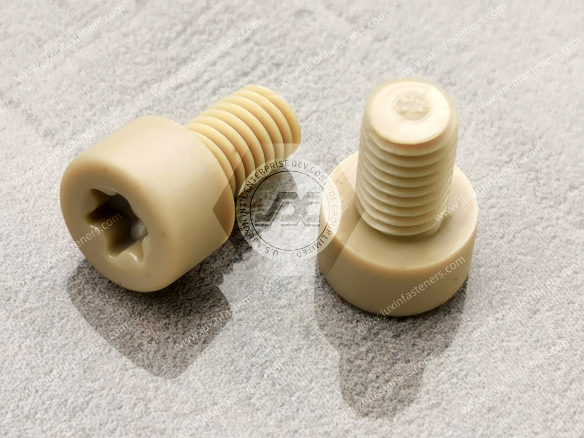
nylon machine screws
plastic washers
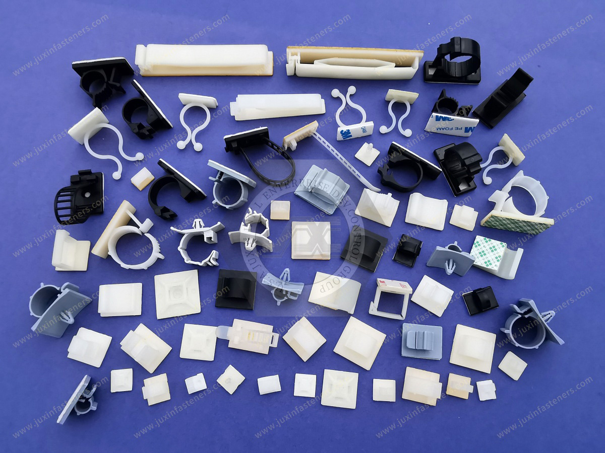
cable tie mounts
wire and cable clips
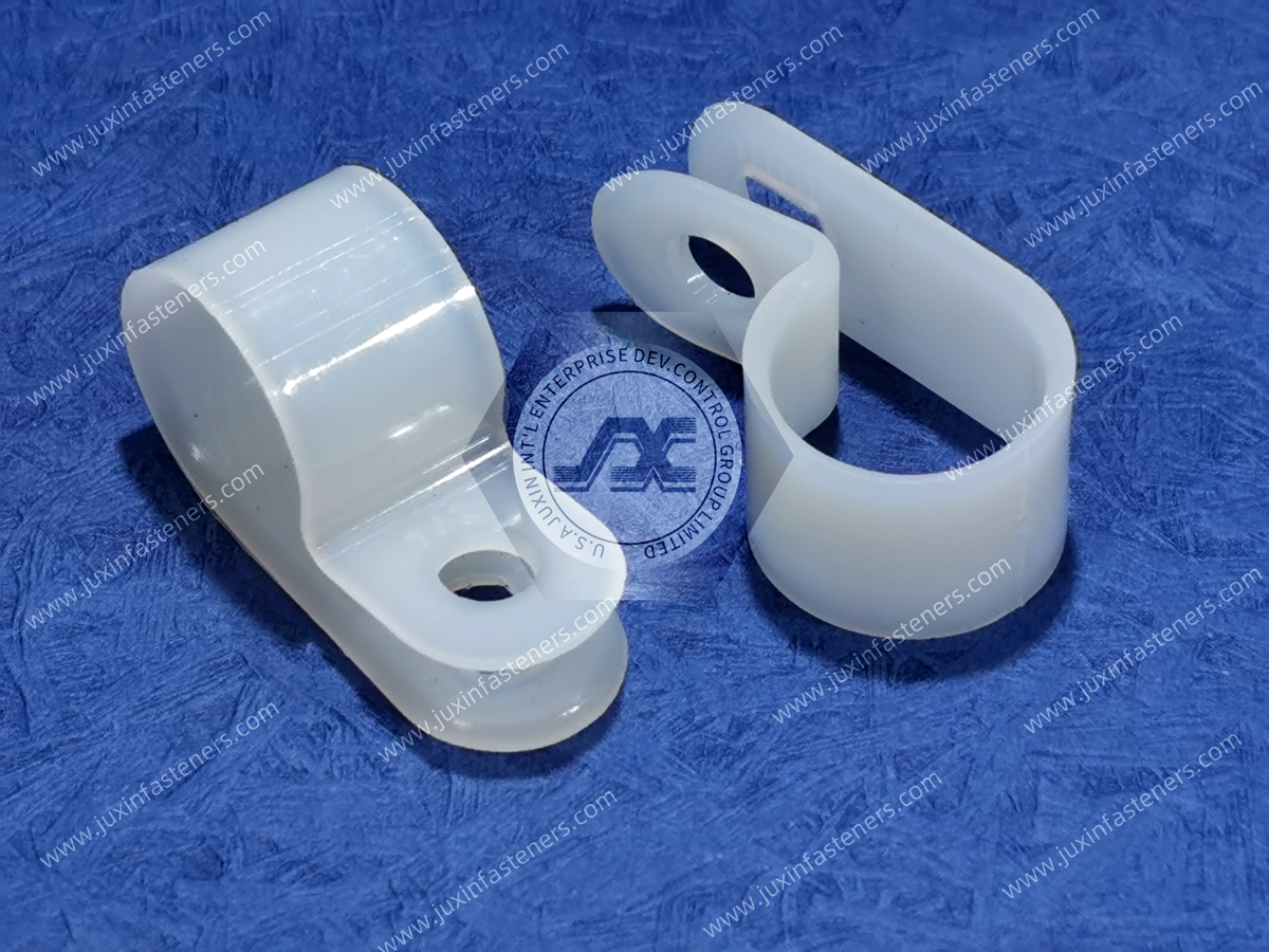
P-clips and screw-mount cable clamps
plastic push rivets
panel hole bushings
air-baffle retainers
card guides
custom molded plastic fasteners
However, there is no single material or fastener geometry that is universally suitable for an “AI server.”
A snap-fit support under a large accelerator board, a cable tie mount near a power harness, a push rivet retaining an airflow baffle,
and a plastic spacer inside an electronics module perform different functions and experience different loads.
Correct component selection should therefore begin with:
Functional Zone → Mechanical Requirement → Thermal Environment → Electrical Architecture → Mating Interface → Material → Geometry → Installation → Validation
Juxin Fasteners supplies standard and custom plastic and nylon fastening components for industrial OEM applications and supports AI server,
HPC, telecommunications, power-electronics, and data center hardware projects using existing part numbers, physical samples,
dimensional specifications, 2D drawings, 3D CAD models, material requirements, and application information.
AI server platforms can contain combinations of:
large multilayer PCBs
GPU or accelerator assemblies
high-current power distribution
high-speed interconnects
high-density cabling
fans
heat sinks
liquid-cooling hardware
airflow ducts
power supplies
backplanes
serviceable modules
Packaging density means that small mechanical components can affect neighboring systems.
For example, changing a PCB standoff height may influence board position, connector alignment, component clearance, or airflow.
Changing a cable clip may alter harness position relative to fans, heat sinks, or serviceable modules.
Changing an airflow-baffle fastener may affect assembly and maintenance access.
Plastic hardware should therefore be evaluated as part of the complete server architecture rather than as generic accessory hardware.
A useful way to select server plastic hardware is to divide the equipment into functional zones.
Typical areas include:
motherboard and GPU baseboard support
accelerator and auxiliary PCB support
internal power-cable routing
signal and control cable management
airflow baffles and ducting
liquid-cooling auxiliary routing
chassis panel interfaces
rack-level structured cabling
serviceable module interfaces
Each area creates a different selection problem.
Large PCBs require carefully controlled mechanical support.
Depending on the design, support hardware may include:
snap-fit PCB supports
nylon standoffs
plastic spacers
insulating pillars
nylon screws
plastic washers
card supports
The objective is not simply to “hold the board above the chassis.”
The complete support system can influence:
PCB position
PCB bow
connector alignment
component clearance
local board stress
vibration response
assembly sequence
serviceability
A common mistake is to treat PCB standoff height as equivalent to electrical creepage or clearance.
They are not the same thing.
Standoff height describes a mechanical spacing dimension.
Electrical creepage and clearance depend on the complete electrical architecture, including:
voltage
conductive geometry
material
surface path
surrounding components
contamination conditions
applicable equipment requirements
A plastic standoff can contribute to component separation, but its height alone does not establish electrical compliance.
Snap-fit PCB supports frequently interact with two different structures:
Board Side → PCB
and
Chassis Side → Sheet Metal / Molded Housing / Other Structure
These interfaces may use different hole dimensions and different locking mechanisms.
Engineering review should therefore distinguish:
PCB hole diameter
PCB hole tolerance
PCB thickness
chassis hole diameter
chassis hole tolerance
chassis thickness
support height
head geometry
board-side locking mechanism
chassis-side locking mechanism
There is no universal PCB mounting-hole size for snap-fit supports.
The board-side retaining feature may depend on PCB thickness.
If the board is outside the intended thickness condition, possible problems can include:
excessive insertion force
incomplete engagement
excessive board movement
damaged locking features
difficult service removal
A replacement support should therefore be evaluated against the actual PCB construction rather than only overall component dimensions.
Large server and accelerator PCBs can experience mechanical loading from:
their own mass
heat sinks
connectors
cables
daughter cards
assembly handling
service operations
Support placement can influence PCB deflection.
Too few supports may allow excessive board movement.
Poorly positioned supports can create local stress or interfere with components.
The correct support arrangement therefore depends on board geometry and the complete assembly.
Connector insertion and removal can introduce localized loads into the PCB.
Examples may include:
power connectors
board-to-board connectors
cable connectors
serviceable modules
If a connector is located far from a support point, insertion force may cause local board deflection.
A useful design question is therefore:
Where does the connector load travel through the PCB into the supporting structure?
PCB support placement should be reviewed together with connector locations rather than independently.
PCB bow can influence:
connector alignment
heat-sink interfaces
component clearance
board-to-board relationships
mechanical stress
Plastic standoffs and PCB supports should therefore be selected and positioned to support the intended board geometry without creating unnecessary local distortion.
Server chassis structures and PCB assemblies can expand differently with temperature.
The mechanical support architecture should therefore avoid unintentionally over-constraining a large PCB where limited relative movement is required.
This becomes more important as:
board dimensions increase
thermal gradients increase
support-point count increases
chassis materials differ from board structures
A support system should provide the required positioning while accounting for the mechanical behavior of the complete assembly.
AI and HPC equipment can contain substantial internal power-distribution cabling.
Depending on the architecture, routing hardware may include:
P-clips
screw-mount cable clamps
cable tie mounts
molded cable clips
custom harness retainers
Cable routing should be evaluated according to the actual cable construction.
Important variables include:
cable OD
bundle dimensions
cable mass
stiffness
jacket material
bend requirements
mounting interface
thermal environment
service access
surrounding components
A large power cable and a small signal harness should not be managed using the same assumptions.
Fan vibration, transportation, installation, service, and equipment operation can create relative movement.
A potential failure path is:
Mechanical Excitation → Cable Movement → Contact with Chassis or Hardware → Repeated Friction → Jacket Wear
Cable management should therefore control routing without creating damaging compression or sharp contact points.
Engineers should review:
clamp fit
clip edges
molding flash
support spacing
nearby sheet-metal edges
cable bend path
connector loading
In high-density server systems, cable routing can affect cooling airflow.
Poorly positioned cable bundles may interfere with intended flow paths or service access.
However, it is overly simplistic to state that a specific plastic clip automatically “improves cooling efficiency.”
The actual thermal effect depends on:
chassis architecture
airflow direction
fan configuration
cable volume
component layout
pressure distribution
thermal solution
The correct design objective is to maintain the intended cable route while minimizing unnecessary interference with the engineered cooling path.
AI servers may use internal baffles, ducts, partitions, or airflow-guiding components to manage cooling.
Depending on the design, lightweight retention hardware may include:
plastic push rivets
snap fasteners
molded retainers
panel clips
custom plastic fasteners
The fastening method should support:
correct baffle position
assembly efficiency
vibration retention
thermal environment
required service access
A fastener does not itself determine airflow performance, but incorrect retention can allow an airflow-control component to move away from its intended position.
Plastic push rivets can provide efficient attachment for selected lightweight internal components.
Selection should consider:
mounting-hole diameter
hole tolerance
stack thickness
grip condition
substrate material
insertion force
retention
vibration
removal requirements
polymer material
temperature
Visually similar push rivets should not automatically be treated as interchangeable.
Their expansion and retention geometries may differ significantly.
Liquid-cooled server architectures introduce additional packaging interfaces around:
cold plates
coolant tubing
manifolds
pumps
connectors
sensors
leak-detection hardware
Plastic fasteners may be useful for selected auxiliary routing or lightweight retention functions, depending on the system design.
For tubing or hose retention, engineers should consider:
tube OD
tube material
allowable compression
bend geometry
thermal expansion
vibration
coolant exposure
service requirements
A generic cable clip should not automatically be assumed suitable for a coolant tube.
The retained component and fluid environment must be evaluated.
Where a liquid-cooling system contains pressurized fluid, the primary pressure boundary and fluid connection require purpose-designed components.
A plastic routing clip may locate or support tubing, but it should not be confused with a pressure-rated fluid connector unless specifically designed and validated for that function.
At rack level, data center equipment may contain:
fiber-optic cabling
high-speed copper interconnects
power cables
management cables
control wiring
Possible cable-management hardware can include:
screw-mount cable tie mounts
push-in tie mounts
cable clips
P-clips
cable retainers
Rack-level selection should consider:
bundle diameter
cable sensitivity
bend radius
rack geometry
service access
cable replacement
airflow paths
installation method
Fiber and high-speed data cables can have specific bend and handling requirements that should be controlled by the cable-system design rather than assumed from the fastener alone.
There is no universal “server-grade nylon.”
Material selection should be driven by the component's actual environment and function.
Possible materials may include, depending on the product:
PA6
PA66
POM / acetal
PBT
PC
other engineered polymers
application-specific high-performance polymers
Not every product is available in every material.
The required polymer should be selected according to:
mechanical requirements
temperature
moisture
flame-performance requirement
electrical requirements
chemical exposure
dimensional stability
manufacturing process
customer documentation requirements
Some server and electrical applications may specify flame-retardant polymers.
A specific PA66 resin may carry a documented UL 94 classification such as V-0 or V-2 under defined tested conditions.
However:
PA66 does not automatically mean UL 94 V-0.
Nylon does not automatically mean flame retardant.
A material-level UL 94 classification does not by itself certify the complete server or data center system.
Where flame performance is required, engineers and procurement teams should define:
required classification
applicable resin grade
relevant thickness condition
documentation requirement
The requirement should then be confirmed for the actual component.
Heat-stabilized polymer grades may be appropriate for components exposed to elevated temperatures.
Potential locations can include areas near:
processors
GPU assemblies
power conversion hardware
power supplies
networking electronics
hot exhaust regions
However, the phrase “heat stabilized” does not establish a universal operating-temperature limit.
Suitability depends on:
resin grade
actual temperature
exposure duration
mechanical stress
moisture
geometry
required service performance
PA6 and PA66 absorb moisture from the surrounding environment.
Moisture conditioning can influence:
dimensions
stiffness
toughness
strength
insertion behavior
retention
snap-fit behavior
creep
stress relaxation
This can matter in multi-point PCB support arrays because small dimensional changes can interact with multiple mounting interfaces across a larger assembly.
However, the actual significance depends on the component geometry, resin grade, environmental condition, and tolerance requirements.
Dry-as-molded material data should not automatically be treated as representative of every long-term installed condition.
Plastic hardware under sustained load can exhibit time-dependent mechanical behavior.
Relevant components may include:
PCB supports
standoffs
cable clamps
cable tie mounts
push rivets
continuously deflected snap features
Creep and stress relaxation depend on:
material
temperature
moisture
stress
geometry
time
For example, a cable clamp that provides strong initial contact pressure should not automatically be assumed to maintain identical clamping behavior throughout service.
Long-term performance should be evaluated according to the actual application.
High-speed fans, pumps, transportation, installation, and equipment operation can generate mechanical excitation.
However, “vibration resistant” should not be treated as a generic material property.
The relevant failure mode depends on the component.
For example:
PCB Support: Does the board remain correctly supported without disengagement or excessive movement?
Cable Clip: Does the harness remain located without chafing?
Push Rivet: Does the retained panel remain seated?
P-Clip: Does the cable remain appropriately constrained?
Air-Baffle Retainer: Does the baffle remain in its intended position?
Component validation should therefore reproduce the relevant interface and loading condition.
Engineering polymers can provide a non-metallic mechanical interface.
This may be useful around electronic assemblies.
However, a plastic fastener does not automatically:
prevent every short circuit
eliminate electrical arcing
establish creepage distance
establish clearance distance
provide a defined dielectric rating
certify insulation coordination
certify the server
These are system-level electrical design issues.
They depend on:
voltage
geometry
polymer grade
conductive surfaces
contamination
equipment architecture
applicable standards
Plastic hardware can contribute to the overall design, but it should not be presented as a standalone electrical safety solution.
Reliability, availability, and serviceability are important considerations in server hardware.
Snap-fit plastic components can be useful where engineers need fast assembly or service access.
However, “tool-free” is not automatically desirable for every component.
Design teams should decide whether the component should be:
permanent
single-use
removable
reusable
field replaceable
This decision affects:
latch geometry
retention force
access
release method
component life
service procedure
A component that is easy to install but impossible to remove without damaging nearby hardware may create service problems.
Conversely, a component designed for repeated removal may require a different locking architecture than a permanent production fastener.
For serviceable server hardware, engineers should evaluate:
Installation → Retention → Release Access → Removal → Reinstallation
rather than insertion alone.
High-volume server production may require plastic components to support efficient assembly.
Important considerations include:
insertion direction
installation force
tactile feedback
visual confirmation
orientation
poka-yoke
tool access
automated placement
component feeding
incomplete-engagement detection
A fastener should therefore be evaluated both in the finished server and on the manufacturing line.
Where automated assembly is used, engineering teams may need to review:
part orientation
gripper access
dimensional consistency
installation-force window
end-effector geometry
engagement detection
risk of component deformation
Automation compatibility is an assembly-system characteristic rather than an inherent property of a particular polymer.
Instead of beginning with a product catalog, engineers can begin with the failure that must be prevented.
Possible consequences:
PCB movement
board bow
connector misalignment
local mechanical stress
Possible consequences:
harness displacement
cable chafing
airflow interference
connector loading
Possible consequences:
baffle movement
unintended airflow bypass
vibration noise
service difficulty
Possible consequences:
cable bundle displacement
local harness loading
interference with fans or modules
Possible consequences:
loose lightweight panel
rattle
displaced internal component
This approach identifies what actually needs to be validated.
| AI / HPC Application Zone | Possible Plastic Hardware | Key Engineering Questions |
|---|---|---|
| GPU / motherboard support | PCB supports, standoffs, spacers, nylon screws | PCB thickness, support height, board bow, connector loads, serviceability |
| Internal power cabling | P-clips, cable clamps, tie mounts | Cable OD, mass, bend path, jacket sensitivity, vibration |
| Signal / control harnesses | Cable clips, tie mounts, retainers | Bundle size, routing, service access, chafing |
| Airflow baffles | Push rivets, snap retainers, custom fasteners | Hole size, stack thickness, thermal environment, removal |
| Liquid-cooling auxiliary routing | Tube clips, custom retainers | Tube OD, compression, temperature, coolant compatibility |
| Panel cable pass-through | Snap bushings, hole protectors | Panel hole, thickness, cable OD, edge protection |
| Rack-level cabling | Cable tie mounts, P-clips, retainers | Bundle geometry, bend limits, rack interface, serviceability |
This matrix is a starting point for engineering review, not a universal specification.
A practical selection sequence is:
Functional Zone → Failure Mode → Thermal Environment → Electrical Architecture → Mating Interface → Material → Geometry → Installation → Serviceability → Validation
Where is the component located?
What happens if it loosens, moves, deforms, or breaks?
What temperature and thermal gradient will the component experience?
Is the component near low-voltage electronics, power conversion, high-current conductors, or another electrical subsystem?
Does it attach to:
PCB
sheet metal
molded housing
cable
tube
baffle
rack structure?
Which polymer properties are actually required?
What dimensions control the fit and function?
How is the component installed?
Will it need to be removed or reused?
What assembly-level evaluation is required?
This creates a much more reliable engineering process than selecting a component simply because it is described as “server plastic hardware.”
Flame performance depends on the actual resin grade and tested conditions.
Mechanical spacing and electrical insulation coordination are different design issues.
PCB hole, board thickness, chassis interface, locking geometry, and support placement also matter.
Large connectors can create localized board deflection during insertion and removal.
Cable routing can affect airflow, but thermal performance depends on the complete chassis design.
Tube compression, material compatibility, and fluid-system requirements differ from cable routing.
Two plastic fasteners that look similar may have different geometry, material, tolerances, and retention behavior.
A secure component can still be unsuitable if technicians cannot release it without damaging the assembly.
These distinctions provide important criteria for both new design and second-source sourcing.
Server OEMs and electronics manufacturers may need second sources for:
supply-chain resilience
capacity expansion
cost evaluation
component obsolescence
redesign
localization
new platform development
The correct objective is not to find a component that looks similar.
It is to identify a technically appropriate candidate that can be validated in the real assembly.
Useful starting information includes:
existing manufacturer
existing part number
OEM internal part number
physical sample
2D drawing
3D CAD model
material specification
application location
mating component
A cross-reference candidate should not automatically be described as a fully interchangeable equivalent.
Small molded hardware often contains functional features that are difficult to capture with a few catalog dimensions.
Examples include:
flexible locking arms
undercuts
snap shoulders
barb geometry
local wall thickness
lead-in angles
release features
anti-rotation geometry
A physical sample combined with drawings and application information can therefore provide much stronger second-source data.
Depending on the component, evaluation should use the actual or representative:
PCB
chassis
mounting hole
cable
cable bundle
airflow baffle
tube
mating hardware
Potential validation items include:
insertion behavior
retention
board support
cable fit
removal
vibration
thermal exposure
environmental conditioning
assembly ergonomics
Requirements should be based on the customer's actual hardware and qualification process.
A structured pathway can follow:
Existing Part → Application Review → Interface Review → Dimensional Review → Material Review → Candidate Cross-Reference
→ Physical Sample → Assembly Validation → Supplier Qualification → Production RFQ
This distinction between cross-reference and qualification is important.
Finding a dimensionally similar component is only one step.
Standard catalog hardware may not fit every high-density server architecture.
Custom components may be appropriate where the design requires:
non-standard PCB support height
unique board locking geometry
unusual chassis interface
integrated cable-management features
restricted installation space
custom release mechanism
specialized resin
custom airflow-baffle attachment
application-specific tube or harness routing
multiple functions integrated into one molded component
Juxin Fasteners can review drawing-based plastic components using customer-provided:
2D drawings
3D CAD models
physical samples
material requirements
mating-component information
application requirements
expected production quantities
A custom-development pathway can follow:
Application Requirement → Interface Review → Material & Geometry Review → Manufacturability Review
→ Sample / Prototype → Assembly Validation → Customer Qualification → Production
Industrial server and electronics procurement may require documentation beyond basic dimensions.
Depending on the project, requirements may include:
material identification
resin specification
dimensional inspection
lot identification
traceability requirements
environmental compliance declarations
flammability documentation
packaging requirements
customer-specific documentation
Where RoHS, REACH, material reports, UL 94 information, or other documentation is required, it should be specified during the RFQ and confirmed for the actual component.
These requirements should not be assumed from a generic product description.
For efficient technical and commercial evaluation, provide as much of the following information as available:
existing manufacturer
existing part number
OEM internal part number
physical sample
2D drawing
3D CAD model
application zone
component function
mating substrate
PCB hole diameter where relevant
PCB thickness
chassis hole diameter
chassis thickness
required standoff height
connector location or relevant assembly load
cable or bundle OD
cable type
tube OD where relevant
mounting-hole diameter
hole tolerance
stack thickness
material or resin requirement
color
operating-temperature requirements
moisture exposure
chemical exposure
vibration requirement
flame-performance requirement where applicable
electrical requirements where applicable
installation method
automation requirement where applicable
removal or reuse requirement
required documentation
sample quantity
production quantity
estimated annual volume
packaging requirements
For second-source projects, sending the existing component together with its actual mating interface can significantly improve the quality of the engineering evaluation.

For a new AI or HPC hardware platform:
Functional Requirement → Application Zone → Mechanical / Thermal / Electrical Review → Interface Definition
→ Material & Geometry Selection → Candidate Component → Sample → Assembly Validation → Production RFQ
For an existing production component:
Existing Part / Physical Sample → Application & Interface Review → Dimensional & Material Review
→ Candidate Cross-Reference → Sample → Assembly Validation → Second-Source Qualification → Production RFQ
For a custom plastic component:
2D/3D Drawing + Application Requirements → Engineering Review → Material & Manufacturability Review
→ Sample / Prototype → Customer Validation → Qualification → Production
This creates a direct technical-commercial path for server OEMs, HPC manufacturers, cloud infrastructure suppliers,
data center equipment manufacturers, engineering teams, procurement organizations, and supplier-development teams.
Juxin Fasteners supplies standard and custom plastic and nylon fastening components for industrial OEM applications,
including PCB supports, standoffs, spacers, nylon screws, plastic washers, cable clips, cable tie mounts, P-clips, cable clamps,
push rivets, panel bushings, and custom molded plastic fasteners.
Engineering and sourcing teams can submit an existing manufacturer part number, competitor part number, physical sample, 2D drawing,
3D CAD model, PCB or chassis interface information, material requirement, application conditions, and estimated purchasing volume for evaluation.
For second-source projects, the objective is not simply to find a plastic component that resembles the existing part.
The objective is to identify a technically appropriate candidate that can be evaluated against the actual PCB, chassis,
cable, thermal environment, assembly process, and service requirements.
For new AI server and HPC platforms, defining the functional zone, mating interface, failure mode, thermal environment,
electrical architecture, material requirement, installation process, and serviceability requirement early in the project creates a more efficient path from engineering review to sampling, qualification, and production sourcing.
Email: info@juxinfasteners.com
Website: www.juxinfasteners.com
 MORE NEWS

Sep. 27, 2026

Sep. 27, 2026

Sep. 27, 2026
Contact Us
Tel.:
+86 020 8621 0320
+86 020 3121 6067
E-mail:
Technical Support:
Navigation
SEND INQUIREY