
Call Us
+86 136 6007 9809
Call Us
+86 136 6007 9809

Sep. 25, 2026
Standard plastic fasteners solve many common assembly requirements, but not every OEM product can be designed around catalog hardware.
AI servers, electric vehicle battery systems, power electronics, semiconductor equipment, medical devices, telecommunications hardware, industrial automation,
HVAC systems, and specialized machinery can require fastening components with proprietary geometry, restricted packaging space, unusual mounting interfaces,
specific polymer requirements, or multiple functions integrated into one molded component.
When an off-the-shelf nylon rivet, cable clip, spacer, retainer, or snap fastener cannot satisfy the assembly,
engineers may need custom molded plastic fasteners or custom injection molded polymer components designed around the actual product architecture.
Custom components can include:
plastic push fasteners
snap-in retainers
cable routing clips
wire harness clips
tube and hose clips
panel retainers
plastic standoffs
spacers
insulating blocks
guide components
latches
custom nylon fasteners
high-performance polymer components
multifunctional molded fastening components
Also searched as custom plastic fasteners, custom injection molded fasteners, engineered plastic fasteners, custom polymer components,
precision plastic hardware, custom nylon fasteners, non-conductive plastic fasteners, custom plastic clips, custom plastic retainers,
and plastic fastener manufacturing, these projects require a different sourcing process from buying a standard catalog fastener.
The development path is typically:
application → functional requirements → 2D/3D geometry → polymer selection → injection molding DFM
→ tooling strategy → T1 samples → dimensional and functional validation → production control
Custom molding becomes relevant when standard hardware creates an engineering compromise.
Common reasons include:
no catalog part fits the available envelope
mounting-hole geometry is proprietary
cable or tube routing requires a special profile
multiple functions need to be integrated
electrical isolation is required
standard polymer performance is unsuitable
installation must be simplified
component weight must be reduced
a legacy component needs a second source
multiple purchased components could potentially be consolidated
The first question should not be:
“Can this component be molded?”
A better question is:
“Does custom molding solve enough mechanical, assembly, sourcing, or lifecycle problems to justify dedicated tooling?”
| Engineering Factor | Standard Plastic Fastener | Custom Molded Plastic Fastener |
|---|---|---|
| Geometry | Existing design | Designed for application |
| Tooling investment | Usually none | Usually required |
| Development time | Shorter | Longer |
| Packaging optimization | Limited | High potential |
| Material choice | Existing options | Project-specific options |
| Functional integration | Limited | Can integrate multiple functions |
| Initial cost | Lower | Tooling and development cost |
| High-volume optimization | Product dependent | Can be designed around production volume |
| Proprietary interface | Limited | Strong fit |
| Engineering validation | Application dependent | Required for custom design |
Custom does not automatically mean better.
It becomes commercially attractive when the application value justifies development and tooling.
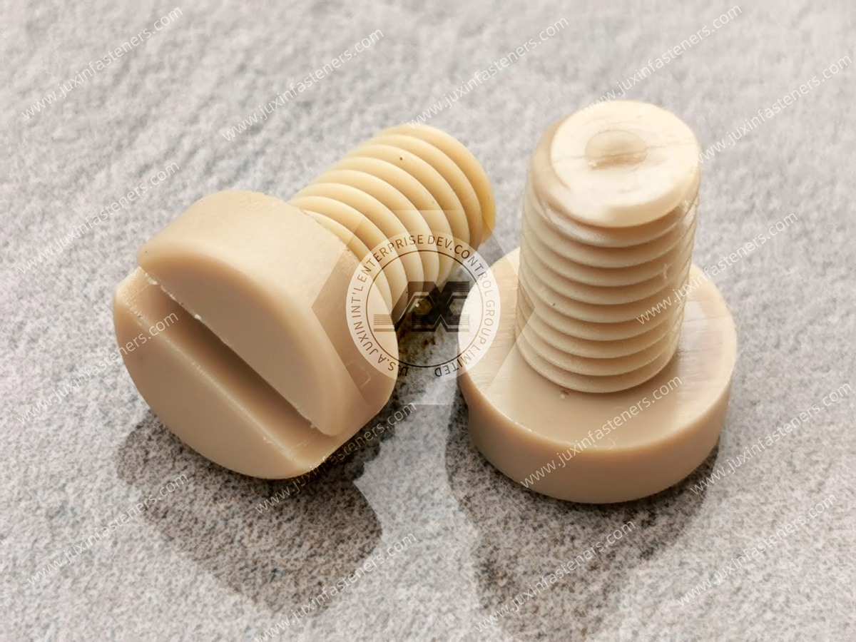
A frequent development mistake is selecting a material before defining the component's job.
First define whether the part must:
retain a panel
hold a cable
route a tube
provide spacing
create a snap-fit connection
electrically isolate components
resist chemicals
survive elevated temperature
permit repeated service
combine several of these functions
Only after the functional requirements are understood should the polymer be selected.
Potential engineering polymers include:
PA6
PA66
glass-filled PA66
POM
PBT
PC/ABS
PPS
PEEK
other application-specific thermoplastics
Each material family has different advantages and limitations.
The resin name alone is not a complete material specification.
PA66 is widely used for molded fastening components because it can provide a useful balance of:
strength
toughness
fatigue resistance
snap-fit capability
moldability
cost efficiency
Potential applications include:
cable clips
push fasteners
retainers
snap-fit components
panel hardware
However, PA66 grade selection matters.
PA66 absorbs moisture from its environment.
Moisture can influence:
dimensions
stiffness
toughness
snap behavior
insertion force
retention
electrical properties
For dimensionally or electrically sensitive components, engineers should consider the material condition expected during:
manufacturing
assembly
qualification
transportation
field service
Glass reinforcement can increase stiffness and dimensional performance in certain applications.
Potential uses include:
rigid guide blocks
brackets
structural polymer components
stiff mounting features
But glass-filled nylon is not automatically better for every fastener.
Snap arms and flexible retention legs depend on controlled elastic deformation.
Increasing material stiffness can reduce the amount of deflection available before excessive strain develops.
Therefore, a highly reinforced polymer that performs well in a rigid bracket may not be the best choice for a flexible snap arm.
Material selection and geometry must be designed together.
Injection molding aligns reinforcement fibers according to local material flow.
This can create direction-dependent properties.
As a result, glass-filled molded components can behave differently depending on:
gate location
flow direction
component geometry
weld-line location
This matters for:
snap arms
thin ribs
mounting legs
clips
highly loaded features
Published material properties are useful for initial engineering comparison.
But actual part performance also depends on:
molded geometry
fiber orientation
processing
moisture
temperature
gate location
weld lines
Final performance should therefore be validated on representative molded components.
POM can offer:
dimensional stability
relatively low moisture absorption
low friction
good molded surface characteristics
It may be useful for:
guides
clips
moving interfaces
snap components
Material selection should still consider:
temperature
chemicals
flammability
loading
regulatory requirements
PBT may be considered for certain electrical and industrial molded components.
Potential characteristics include:
dimensional stability
electrical performance
availability of reinforced or flame-retardant grades
The correct grade depends on the project requirements.
PPS can be considered for applications involving combinations of:
elevated temperature
dimensional stability
chemical exposure
electrical requirements
Reinforced PPS is used in demanding industrial and electrical applications.
However, filler content and resin grade should be selected according to the geometry and required mechanical behavior.
PEEK is a high-performance polymer considered for demanding environments involving combinations of:
elevated temperature
chemical exposure
dimensional requirements
specialized industrial conditions
Potential applications can include:
semiconductor equipment
specialized medical equipment
high-temperature machinery
certain cooling or power-electronics systems
PEEK should not be specified simply because it is considered a premium polymer.
Its higher material and processing cost must be justified by the application.
| Engineering Requirement | Material Direction to Evaluate |
|---|---|
| General-purpose snap-fit component | PA66 or other suitable engineering polymer |
| Low moisture sensitivity | POM, PBT or another suitable polymer |
| High rigidity | Reinforced engineering polymer |
| Flexible snap feature | Evaluate unfilled or suitably modified polymer |
| Elevated-temperature service | PPS, PEEK or suitable heat-stabilized polymer |
| Chemical exposure | Select after chemical compatibility review |
| Electrical application | Evaluate resin-specific electrical properties |
| Flammability requirement | Select documented grade meeting required classification |
| Outdoor exposure | UV-stabilized material where required |
The final material should be selected using the actual operating conditions.
If a project requires a UL 94 classification, the requirement should be identified during material selection.
Do not assume:
all PA66 has the same classification
all flame-retardant nylon is V-0
all PPS has the same classification
all PEEK has the same classification
UL 94 performance is associated with the specific material grade and tested thickness.
A polymer may have documented flammability performance.
That does not automatically certify the finished:
server
battery system
medical device
electrical enclosure
industrial machine
Equipment compliance depends on the complete product and applicable standards.
Potential chemical exposure can include:
oils
coolants
cleaning agents
fuels
detergents
disinfectants
process chemicals
Chemical resistance should be evaluated using:
polymer grade
chemical
concentration
temperature
exposure duration
mechanical stress
Statements such as “chemical resistant” are too broad for critical sourcing decisions.
A custom plastic component can function perfectly in CAD and still be difficult to mold consistently.
Injection molding DFM evaluates whether the design can be produced repeatedly without creating unnecessary:
warpage
sink
flash
voids
difficult ejection
weld-line weakness
tooling complexity
DFM should occur before final tooling release.
Uniform wall thickness is generally desirable because major thickness changes can create:
uneven cooling
shrinkage variation
sink
internal stress
warpage
However, there is no single universal wall thickness for all custom plastic fasteners.
Appropriate thickness depends on:
polymer
flow length
component size
geometry
mechanical requirement
tooling
molding process
Generic molding guides often publish preferred wall-thickness ranges.
Those ranges can be useful during concept design.
They should not automatically become mandatory dimensions on an OEM drawing without considering the selected resin and component geometry.
When thickness must change, gradual transitions can help manage:
flow
cooling
stress concentration
cosmetic defects
The appropriate transition depends on the design.
Ribs can increase stiffness without creating a fully thick section.
They can be useful in:
guide blocks
standoffs
housings
support features
But excessively thick rib intersections can contribute to:
sink
shrinkage
distortion
Rib dimensions should be optimized for the selected polymer and appearance requirements.
Draft assists molded-part release from the tool.
Required draft depends on:
resin
surface texture
feature depth
tooling
cosmetic requirements
There is no universal draft angle that applies to every plastic fastener feature.
Snap legs require particular care because ejection geometry and functional geometry interact.
A poorly designed draft can change:
snap engagement
insertion force
retention
Tooling and product engineers should review these features together.
Custom plastic fasteners frequently contain:
barbs
hooks
locking tabs
snap arms
These features can create molding undercuts.
Depending on geometry, tooling may require:
lifters
slides
collapsible cores
flexible stripping
design modification
Undercuts can significantly influence tooling complexity and cost.
During DFM, changing a locking feature or parting direction may eliminate the need for a side action.
That can affect:
tooling cost
mold complexity
maintenance
cycle reliability
This is why DFM should happen before a drawing is frozen.
Gate location influences how polymer fills the cavity.
It can affect:
flow direction
weld lines
fiber orientation
shrinkage
appearance
residual stress
The gate should not be selected only according to cosmetic convenience.

Weld lines form where separate flow fronts meet.
Their location can matter when they intersect:
snap arms
retention legs
thin sections
highly stressed features
For a critical snap-fit fastener, gate and weld-line strategy can directly affect mechanical reliability.
On a simple cosmetic part, gate location may appear to be primarily a molding issue.
On a molded fastener, it can influence the mechanical performance of the retention feature.
Product engineering and tooling engineering should therefore review gate strategy together.
Thermoplastics shrink during cooling.
Shrinkage depends on:
resin
filler
flow direction
wall thickness
processing
mold temperature
cavity geometry
A single nominal shrinkage percentage should not be assumed to predict every dimension.
Warpage can result from:
uneven cooling
non-uniform thickness
fiber orientation
asymmetric geometry
processing conditions
Warpage is particularly important where the component must fit:
narrow slots
sheet-metal holes
cable channels
mating housings
For sufficiently complex components, simulation may help evaluate:
filling
pressure
weld lines
air traps
fiber orientation
cooling
warpage risk
Whether simulation is necessary depends on project complexity and risk.
Many custom plastic fasteners rely on snap-fit features.
A snap design should consider:
allowable deflection
strain
insertion force
retention force
material
temperature
moisture
creep
number of assembly cycles
A snap intended for one-time assembly can be optimized differently from one requiring repeated service.
Define:
expected removal
reuse cycles
removal tool
acceptable permanent deformation
before finalizing the geometry.
Plastic components can change under sustained load.
This is particularly important for:
clips
snap arms
clamps
retaining legs
A component that provides high initial clamping force may provide lower force after long-term temperature exposure.
Where long-term retention matters, qualification may need to consider:
time
temperature
environmental conditioning
vibration
The correct test depends on the application.
One of the strongest reasons to consider custom plastic hardware is functional integration.
A molded component may combine functions such as:
mounting
spacing
cable routing
anti-rotation
alignment
insulation
This can potentially reduce separate BOM items.
A conventional assembly might use:
metal screw
spacer
cable clip
A custom molded component might integrate:
snap-in mounting feature
spacer body
cable-retention feature
Whether this improves cost depends on production volume and tooling economics.
Combining several functions into one component creates dependencies.
If one feature fails, the entire component may need redesign or replacement.
Before consolidating parts, evaluate:
failure modes
serviceability
tooling complexity
replacement strategy
tolerance stack
Part consolidation should simplify the system without creating an unacceptable single point of failure.
The commercial comparison should include more than component unit price.
Consider:
component price + tooling amortization + assembly labor + secondary hardware + inventory + inspection + rework + service cost
This provides a more realistic sourcing comparison.
Custom molded plastic fasteners can support specialized server and cooling architectures.
Potential applications include:
custom cable clips
liquid-cooling tube guides
sensor-wire retainers
airflow-baffle fasteners
power-equipment insulating components
Requirements can include:
restricted packaging space
flammability requirements
elevated temperature
electrical isolation
serviceability
Custom tube-routing components may be required when standard clips cannot accommodate:
tube diameter
bend path
available space
mounting interface
The design should consider:
tube compression
thermal expansion
pressure-induced movement
vibration
coolant compatibility
Custom plastic components can be used in:
battery packs
electrical enclosures
BMS assemblies
wire harness routing
sensors
charge-port systems
thermal-management hardware
Potential requirements include:
vibration
temperature cycling
chemicals
electrical isolation
automotive documentation
The exact material and validation program should follow the application.
Custom insulating blocks, cable guides, retainers, and mounting components can support electrical packaging.
However, a plastic component should not independently be described as establishing complete high-voltage safety.
System-level requirements such as:
creepage
clearance
dielectric withstand
insulation coordination
must be addressed by the complete design.
Semiconductor manufacturing equipment can require custom polymer components for:
wafer handling
chemical delivery
equipment fixtures
precision positioning
electrical isolation
Potential material considerations include:
chemical compatibility
cleanliness
temperature
dimensional stability
contamination requirements
PEEK, PPS, and other engineering polymers may be evaluated depending on the application.
A polymer component for semiconductor equipment may require application-specific controls such as:
cleanliness
ionic contamination
extractables
outgassing
trace metals
particle generation
These requirements should be specified by the equipment manufacturer where applicable.
Potential applications include:
diagnostic equipment
analyzer hardware
cable routing
fluid-line clips
equipment covers
carts
Material selection may need to consider:
cleaning chemicals
appearance
serviceability
regulatory requirements
Do not infer medical suitability from the polymer name alone.
Custom molded hardware can support:
sensor routing
pneumatic line management
electrical enclosures
lightweight guards
custom machine interfaces
Dynamic cable applications require particular care because a static clip should not automatically be used in continuous-flex cable systems.
Potential applications include:
fiber routing
cable management
outdoor enclosures
radio equipment
network hardware
Outdoor systems may require:
UV stabilization
wider temperature capability
humidity resistance
A structured custom development program generally begins with engineering data.
Useful inputs include:
2D drawing
3D STEP model
physical sample
mating component drawing
application description
Before tooling, review:
wall thickness
draft
undercuts
parting line
gate strategy
ejector locations
critical dimensions
cosmetic surfaces
snap features
expected shrinkage
tolerance feasibility
The purpose is to identify manufacturing risk before steel is cut.
Tooling design depends on:
component size
geometry
resin
volume
cavity count
dimensional requirements
required tool life
A high-volume program may justify a different mold architecture from a low-volume specialized component.
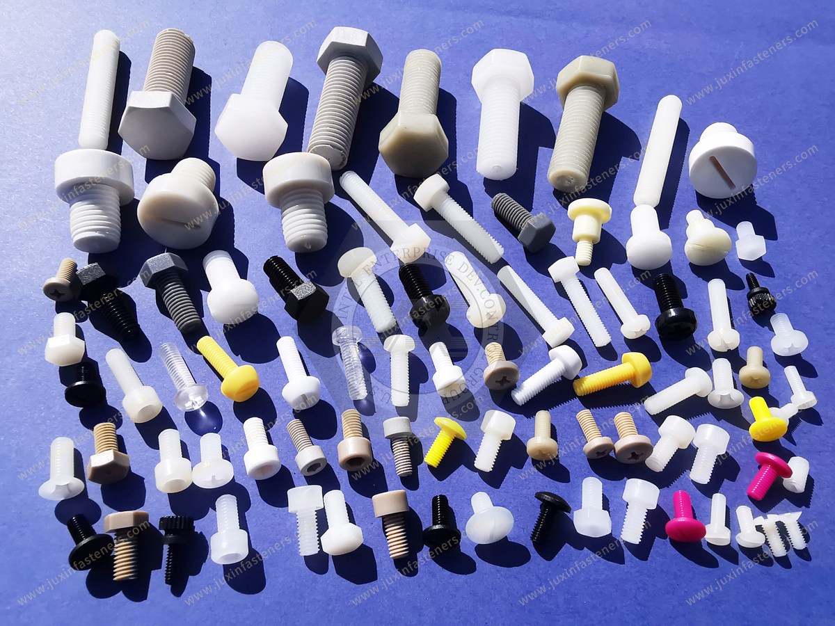
Higher cavity count can increase output.
However, more cavities can also introduce additional challenges involving:
cavity balance
dimensional consistency
tooling complexity
maintenance
The correct cavity strategy should be based on annual demand and quality requirements.
Increasing cavity count can reduce theoretical molding cost per part.
But the decision should also consider:
tooling investment
demand stability
cavity-to-cavity variation
maintenance
spare capacity
Procurement should evaluate total program economics.
Initial molded samples allow evaluation of:
basic dimensions
appearance
assembly fit
snap behavior
molding defects
T1 samples are part of the development process rather than proof that the design is fully production-ready.
T1 evaluation may identify the need to adjust:
dimensions
gate
venting
snap geometry
surface finish
tooling features
This is normal in custom molding development.
Critical dimensions should be identified on the drawing.
Inspection methods can depend on:
geometry
tolerance
accessibility
Possible methods include:
calipers
micrometers
optical measurement
CMM
gauges
Not every dimension requires the same measurement technology.
FAI can document whether initial production samples meet drawing requirements.
The required report format should follow the customer's quality system.
Where statistical process capability is required, the customer should define:
CTQ characteristics
sampling
required indices
production conditions
A universal Cpk requirement should not be assumed for every custom plastic component.
Automotive and certain other OEM programs may require PPAP.
The required submission level and documentation should be agreed with the customer.
Depending on the project, requirements may include:
dimensional results
material documentation
process flow
PFMEA
control plan
measurement-system information
capability studies
Part Submission Warrant
Do not assume every custom plastic fastener project requires PPAP Level 3.
Automated vision inspection can be useful for detecting certain defects such as:
flash
missing features
gross dimensional variation
molding defects
Whether 100% sorting is required should be defined according to:
risk
production volume
customer requirements
control plan
Custom tooling introduces a commercial issue that standard fastener purchasing does not:
Who owns the mold?
The sourcing agreement should clarify:
tooling ownership
payment terms
tool location
maintenance responsibility
expected tool life
storage
replacement
transfer rights where applicable
When a program is being developed for long-term OEM production, tooling ownership and transfer terms can affect future:
second sourcing
capacity expansion
supplier changes
business continuity
Procurement should address these terms during tooling approval.
Custom molded components should have controlled revision management.
Changes involving:
resin
filler content
tooling
cavity
gate
geometry
processing
can affect performance.
Customer notification requirements should be agreed during supplier qualification.
Second sourcing a custom molded component can be more complex than buying another standard fastener.
A replacement supplier may need to reproduce:
geometry
material
functional performance
appearance
tooling output
Where the original mold cannot be transferred, new tooling may be required.
If the original drawing is unavailable, a sample can support:
dimensional measurement
geometry reconstruction
interface evaluation
functional analysis
However, a physical sample cannot reliably reveal:
exact resin grade
filler percentage
flame-retardant formulation
original processing conditions
qualification history
Unknown requirements should be identified rather than invented.
For custom molded plastic fasteners, custom plastic clips, custom nylon fasteners, precision polymer components, custom injection molded fasteners,
or engineered plastic hardware, provide as much of the following information as possible:
2D engineering drawing
3D STEP model
existing physical sample where applicable
application
mating-component information
critical dimensions
tolerances
CTQ characteristics
functional requirements
insertion force where applicable
retention force where applicable
mechanical load
polymer preference
filler or reinforcement requirement
color
flammability requirement
operating temperature
moisture exposure
chemical exposure
UV exposure
electrical requirements
serviceability requirement
reuse requirement
appearance requirements
allowable flash or cosmetic requirements where controlled
required inspection documentation
FAI requirements
PPAP requirements where applicable
sample quantity
Estimated Annual Usage
expected production batch size
target tooling schedule
target production date
packaging requirements
If the material has not yet been finalized, provide the functional and environmental requirements so candidate polymers can be evaluated.
Before releasing a custom plastic fastener design, ask:
What is the primary function?
What load must it carry?
Is the feature rigid or flexible?
Is snap action required?
Is repeated removal required?
What mating geometry is controlled?
What polymer characteristics are required?
Will nylon moisture absorption matter?
Is reinforcement appropriate?
Could reinforcement reduce required flexibility?
What temperature applies?
What chemicals are present?
Is UV exposure expected?
Is flame retardancy required?
Are electrical properties important?
Can the design be molded without unnecessary side actions?
Where can the gate be located?
Could weld lines cross a highly stressed snap feature?
Which dimensions are truly CTQ?
What validation is required?
These questions create a stronger design before tooling investment begins.
For supplier qualification, consider:
Can the supplier review both 2D and 3D engineering data?
Can DFM feedback be provided before tooling?
What tooling architecture is proposed?
What cavity count is proposed?
Who owns the mold?
What mold maintenance terms apply?
What polymer grade is proposed?
Can material documentation be supplied?
How will engineering changes be controlled?
What dimensional inspection can be provided?
Can samples be supplied before production release?
Can FAI be provided if required?
Can PPAP be supported where required?
What production capacity is available?
What lot traceability is available?
How will tooling revisions be documented?
Can second-source or capacity-expansion requirements be supported?
Identify why a standard component does not work.
Supply:
2D drawing
3D CAD
mating geometry
functional requirements
Evaluate:
mechanical behavior
flexibility
temperature
moisture
chemicals
electrical requirements
flammability
Evaluate:
wall thickness
draft
ribs
undercuts
gate location
weld lines
parting line
ejection
shrinkage
warpage
Define:
mold architecture
cavity count
tool ownership
expected production volume
maintenance requirements
Tool construction follows the approved geometry and agreed tooling plan.
Initial samples are evaluated for:
dimensions
fit
function
appearance
Adjust the tool or component design according to sample results.
Depending on project requirements, validation may include:
dimensional inspection
insertion testing
retention testing
assembly testing
environmental conditioning
thermal exposure
chemical exposure
vibration
FAI, PPAP, or other documentation can be prepared where required by the customer.
Production controls should follow the approved:
drawing
resin
tooling revision
inspection plan
packaging requirements
A successful custom molded plastic fastener program is not simply an injection molding project.
It connects:
product design → polymer engineering → DFM → tooling → validation → quality control → procurement → production supply
For design engineers, this helps convert functional requirements into moldable geometry.
For tooling and manufacturing engineers, it reduces avoidable production risk.
For Supplier Quality, it creates measurable approval requirements.
For procurement and supplier-development teams, it establishes the commercial and technical framework for tooling investment, supplier qualification, change control, second sourcing, and recurring production.
JUXIN FASTENERS supplies standard and custom plastic and nylon fastening components for industrial OEM applications.
Product categories include:
custom molded plastic fasteners
custom nylon fasteners
plastic push rivets
cable routing clips
wire harness clips
tube and hose clips
plastic panel retainers
snap-fit components
plastic standoffs
plastic spacers
nylon screws
nylon nuts
nylon washers
threaded inserts for plastics
custom fastening components manufactured to customer drawings or samples
Applications can include:
AI server and data center equipment
automotive and EV systems
electrical and power electronics
semiconductor equipment
medical equipment
industrial automation
telecommunications
HVAC and thermal management
Custom projects can begin from:
customer 2D drawing
3D STEP model
physical sample
existing part number
mating-component drawing
functional requirement
Depending on the project, the development and sourcing path can include:
drawing review
DFM review
polymer selection review
custom geometry evaluation
tooling quotation
sample production
dimensional inspection
customer assembly trials
second-source evaluation
production-volume sourcing
customer-required quality documentation
Actual mechanical strength, insertion force, retention force, electrical properties, flammability performance, operating-temperature capability,
chemical resistance, dimensional stability, and service life depend on the selected polymer grade, reinforcement, molded geometry, tooling design, processing conditions, environment, and customer application.
For custom molded plastic fastener development, DFM review, drawing-based sourcing, physical-sample evaluation, custom tooling,
evaluation samples, second-source qualification, or production-volume RFQs, send your technical requirements to JUXIN FASTENERS.
Email: info@juxinfasteners.com
Website: www.juxinfasteners.com
 MORE NEWS

Sep. 25, 2026

Sep. 25, 2026

Sep. 25, 2026
Contact Us
Tel.:
+86 020 8621 0320
+86 020 3121 6067
E-mail:
Technical Support:
Navigation
SEND INQUIREY