
Call Us
+86 136 6007 9809
Call Us
+86 136 6007 9809

Sep. 27, 2026
Standard plastic fasteners solve many industrial assembly requirements, but OEM equipment frequently contains fastening and retention interfaces that cannot be addressed effectively with an off-the-shelf component.
A restricted installation envelope, non-standard panel hole, unusual cable diameter, application-specific snap geometry, unique PCB interface,
special material requirement, integrated locating feature, or legacy component can create the need for a custom molded plastic fastener or drawing-based polymer component.
These parts may include:
custom plastic push rivets
custom fir tree fasteners
custom cable clips
custom wire harness retainers
custom P-clips and cable clamps
custom PCB supports
custom plastic standoffs
custom spacers
custom snap-fit fasteners
custom panel retainers
custom bushings and grommets
custom strain relief components
custom nylon screws and fastening hardware
custom molded plastic brackets
application-specific polymer components
Developing these parts requires more than converting a metal component into plastic or sending a 3D CAD file to an injection molder.
A successful custom molded component must simultaneously satisfy:
Assembly Function + Mating Interfaces + Material Behavior + Injection-Molding Constraints + Tolerance Requirements + Installation Process
+ Service Environment + Validation Requirements + Commercial Production Needs
This interaction is particularly important for plastic fasteners because many of their functional features—barbs, snap arms, locking fingers,
flexible hinges, interference fits, retaining shoulders, and compression features—depend directly on controlled elastic or time-dependent polymer deformation.
Juxin Fasteners supports standard and custom plastic fastening projects for industrial OEM applications using customer drawings,
3D CAD models, existing manufacturer part numbers, physical samples, mating-component information, material requirements, and application conditions.
For custom projects, the objective is not simply to reproduce a shape.
The objective is to develop or reproduce the required fastening function within a manufacturable and commercially viable molded component.
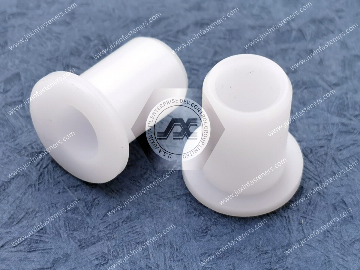
Custom development can be considered when a standard catalog component cannot satisfy the actual assembly interface.
Typical reasons include:
non-standard mounting holes
unusual panel thickness
restricted packaging space
special grip range
unique cable or tube diameter
application-specific retention requirement
custom PCB support height
integrated anti-rotation features
special installation direction
tool-free assembly requirements
service-release requirements
specialized polymer requirements
multiple functions combined into one molded component
replacement of a discontinued legacy component
second-source development for a proprietary existing part
The decision should begin with the functional requirement rather than with the assumption that customization is necessary.
Where a standard component can meet the requirement with acceptable validation, it may provide a simpler sourcing path.
Where the mating interface or performance requirement is genuinely unique, custom molding can create a better technical solution.
One of the most useful principles in custom plastic fastening design is:
Do not begin with the plastic part alone. Begin with what the plastic part must connect, retain, locate, protect, or separate.
For example, a custom fir tree fastener cannot be engineered correctly without understanding the mounting hole.
A custom P-clip cannot be defined correctly without understanding the cable or hose.
A custom PCB support cannot be developed correctly without understanding the PCB and chassis interfaces.
A custom snap-fit component cannot be finalized without understanding how it will be assembled and whether it must later be removed.
The custom component and its mating hardware form a mechanical system.
Before finalizing component geometry, engineering teams should identify the interfaces controlling the design.
These may include:
panel hole diameter
panel thickness
stack thickness
substrate material
PCB hole diameter
PCB thickness
cable outside diameter
cable jacket properties
tube diameter
retained-part geometry
installation direction
available assembly space
neighboring components
This approach reduces the risk of producing a dimensionally accurate component that does not function correctly in the real assembly.
Transitioning a custom plastic fastener from an engineering requirement to a qualified production component generally requires several connected stages.
A practical development sequence is:
Requirement Definition → Drawing / CAD / Sample Review → Functional Interface Review → DFM Review → Material Selection
→ Tolerance Strategy → Tooling Strategy → Prototype or Initial Sample → Assembly Validation → Tool Qualification → Production Release
The exact sequence depends on the project, geometry, production volume, tooling approach, and customer qualification requirements.
Engineering teams can begin with one or more of the following:
2D technical drawing
3D CAD model
STEP file
IGES file
physical sample
existing manufacturer part number
assembly drawing
mating-component drawing
application photographs
functional requirements
The most useful RFQ package includes more than the plastic component itself.
Where available, customers should also provide:
annual demand
order quantity
mating-component information
material requirement
operating environment
installation method
critical dimensions
validation requirements
documentation requirements
DFM—Design for Manufacturability—evaluates whether the proposed geometry can be molded consistently while preserving the intended function.
A meaningful DFM review can examine:
wall thickness
wall transitions
draft
ribs
bosses
gussets
undercuts
snap features
parting lines
gate strategy
ejector locations
mold-release direction
potential sink
potential warpage
critical dimensions
tooling complexity
The objective is not merely to make the component easier to mold.
The objective is to balance function, manufacturability, dimensional consistency, tooling complexity, and production economics.
Material selection should follow the application requirements.
Possible engineering polymers may include, depending on the project:
PA6
PA66
POM / acetal
PBT
PC
selected high-performance thermoplastics such as PEEK
other application-specific polymers
Special formulations may include, where required:
heat-stabilized grades
UV-stabilized grades
impact-modified grades
flame-retardant grades
reinforced grades
other application-specific resin systems
No polymer family should be selected solely because it is commonly described as “high performance.”
The actual resin grade must be matched to the application.
Prototype strategy depends on what must be learned.
Possible early samples may be used to evaluate:
overall geometry
assembly clearance
component location
ergonomics
basic fit
mating-component relationships
However, a prototype made by one manufacturing process should not automatically be assumed to reproduce the mechanical behavior of the final injection-molded component.
This is especially important for functional snap features and highly stressed flexible elements.
After the design and tooling strategy are agreed, production tooling can proceed according to the project plan.
Tool trials and sample evaluation can then be used to confirm:
dimensions
molding behavior
assembly
fit
retention
appearance where relevant
functional performance
Production release should follow the customer's required qualification and approval process.
Wall thickness strongly influences injection molding.
Abrupt changes in section thickness can contribute to:
differential cooling
sink
internal stress
warpage
inconsistent shrinkage
longer cooling time
This does not mean every feature must have exactly identical wall thickness.
Functional geometry may require variation.
The engineering objective is to avoid unnecessary mass concentrations and abrupt transitions while maintaining the strength and function required by the component.
Metal-part design logic does not always translate directly into injection-molded plastic design.
Increasing local thickness can sometimes increase stiffness, but it can also create:
sink marks
cooling imbalance
warpage
increased cycle time
dimensional inconsistency
Where appropriate, structural geometry such as ribs or gussets may provide a more efficient way to increase stiffness than simply creating a thick solid section.
Draft helps a molded component release from the tooling.
The required draft is not governed by one universal value.
Appropriate draft depends on factors such as:
resin
surface texture
feature depth
mold construction
geometry
ejection strategy
cosmetic requirements
Values such as 0.5° or 1° may appear in general design guidance, but they should not be treated as a universal minimum for every custom plastic fastener.
Draft should be determined during DFM for the actual component and tooling design.
Ribs and gussets can increase stiffness without requiring a fully solid thick section.
They may be useful in:
mounting feet
clip bodies
brackets
standoffs
structural transitions
However, rib geometry must also be designed with molding behavior in mind.
Poorly proportioned ribs can contribute to sink or molding difficulties.
Their dimensions should therefore be determined in relation to the surrounding wall and resin rather than by a universal rule.
Plastic fasteners frequently rely on undercuts.
Examples include:
fir tree barbs
snap hooks
retaining lips
locking shoulders
panel-engagement features
These features can create tooling complexity because they may prevent straight-line mold release.
Possible tooling or design approaches can include:
slides
lifters
collapsible cores
flexible part deformation
alternative parting strategies
geometry redesign
The correct solution depends on the component.
Not every undercut should automatically be removed.
Some undercuts are essential to fastening function.
The engineering question is:
Does the functional value of the undercut justify the tooling and manufacturing complexity it creates?
This is an important DFM decision because simplifying geometry can reduce tooling complexity, but removing a critical retention feature can compromise the component's function.
Parting lines can influence:
appearance
flash location
dimensional control
assembly
cable contact
sealing surfaces
snap behavior
For a plastic fastener, a parting line located across a functional contact surface may be more important than one located on a non-functional exterior area.
Therefore, parting-line strategy should be considered during DFM rather than treated only as a tooling detail.
Gate location influences how molten polymer fills the cavity.
Depending on geometry and material, it can affect:
filling pattern
weld lines
orientation
shrinkage
appearance
local mechanical behavior
gate witness location
A gate should not be placed solely for molding convenience without considering the functional surfaces of the component.
For example, a visible gate witness on a cable-contact surface, mating interface, or critical snap feature may be undesirable.
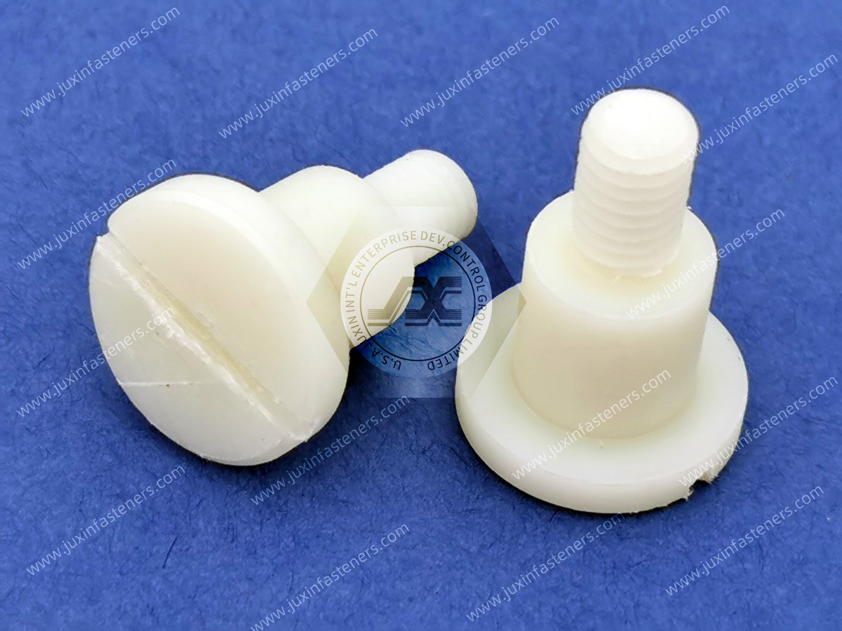
Where multiple flow fronts meet, weld or knit lines may form.
Their significance depends on:
resin
geometry
process
load direction
component function
If a weld line occurs in a highly stressed snap arm or retention feature, it may require additional engineering review.
This is one reason why gate strategy and fastener function must be considered together.
Ejector systems remove the molded part from the tool.
Ejector locations can leave witness marks and introduce local loads during ejection.
They should be reviewed relative to:
functional surfaces
sealing surfaces
cosmetic areas
thin walls
flexible snap features
mating interfaces
An ejector mark may be harmless on one surface and unacceptable on another.
Thermoplastics shrink as they cool, but shrinkage is not a single fixed value that can be applied universally to every component made from the same polymer family.
Actual molded dimensions can be influenced by:
resin grade
reinforcement
geometry
wall thickness
flow direction
gate location
mold temperature
processing conditions
cavity design
Therefore:
Material Name ≠ Universal Shrink Rate
Shrinkage should be addressed through material data, tooling design, molding experience, and dimensional validation.
Warpage can result from uneven shrinkage and internal stress.
Risk may increase with:
large flat sections
asymmetric geometry
non-uniform walls
fiber orientation in reinforced materials
uneven cooling
gate location
A CAD model can be dimensionally perfect while the molded component behaves differently after processing.
DFM should therefore consider the molded state rather than only nominal CAD geometry.
A common mistake is to apply unnecessarily tight tolerances to every dimension.
This can increase:
tooling complexity
process-control requirements
inspection burden
rejection risk
cost
Instead, dimensions should be separated into categories.
These directly influence fit or performance.
Examples may include:
panel engagement diameter
snap location
cable-clamping diameter
PCB support height
mating shoulder
locking feature
These control relationships with mating parts.
These may tolerate broader variation without affecting function.
The engineering objective is:
Control tightly what affects function; avoid unnecessary precision where it adds no functional value.
Custom plastic fasteners rarely operate alone.
Their performance may depend on tolerance stack-up across:
molded fastener
mounting hole
panel thickness
mating component
cable OD
PCB thickness
assembly position
A fastener dimension can be within tolerance while the complete assembly still fails if the combined stack-up is unfavorable.
Functional validation should therefore consider the mating components.
Snap-fit fasteners rely on controlled deformation.
A typical snap feature experiences:
Insertion → Elastic Deflection → Engagement → Recovery → Retention
If deflection is excessive relative to the material and geometry, possible outcomes include:
permanent deformation
whitening
cracking
reduced retention
difficult assembly
If deflection is insufficient, the snap may not engage effectively.
Snap-fit design should therefore consider:
material
feature length
section geometry
strain
insertion direction
lead-in angle
retention geometry
required release
expected number of assembly cycles
A custom fastener should not simply maximize retention.
High retention can sometimes create excessive installation force.
For production assemblies, engineers need an appropriate relationship between:
Installation Effort ↔ Secure Engagement ↔ Required Retention ↔ Service Removal
The optimum balance depends on the application.
Some custom fasteners are installed once and remain in the assembly.
Others must support field service.
A reusable clip may require different geometry and strain conditions from a permanent snap-fit component.
Therefore, the design brief should state whether the component is intended to be:
permanent
single-use
removable
reusable
This requirement should be defined before tooling.
Material selection should begin with the operating environment and failure mode.
A useful sequence is:
Mechanical Load → Temperature → Moisture → Chemical Exposure → Electrical Requirement → Flame Requirement → Dimensional Requirement → Manufacturing Requirement → Resin Grade
This prevents the common error of selecting a material by name before defining what it needs to do.
PA66 and PA6 are widely used engineering polyamides.
Depending on grade and application, they can provide useful combinations of:
strength
toughness
wear resistance
fatigue behavior
moldability
They are commonly considered for:
clips
retainers
snap-fit fasteners
cable hardware
panel fasteners
selected standoffs
However, both materials are hygroscopic.
Moisture must be considered where dimensional stability or retention behavior is important.
PA6 and PA66 absorb moisture.
Moisture conditioning can influence:
dimensions
stiffness
toughness
strength
snap behavior
insertion force
retention
creep
stress relaxation
A custom nylon component should therefore not be evaluated only in the dry-as-molded state when the actual application will experience a different environmental condition.
The importance depends on the specific resin grade, geometry, environment, and function.
POM can provide:
relatively low moisture absorption
dimensional stability
low friction
useful fatigue behavior
good wear characteristics
These properties can make it relevant to selected precision or moving components.
However, POM is not automatically the best material for every precision plastic fastener.
Chemical environment, temperature, flammability requirements, mechanical loads, and manufacturing requirements must still be considered.
High-performance polymers such as PEEK may be considered where the application justifies their properties.
Potential reasons can include demanding combinations of:
temperature
chemical exposure
mechanical performance
electrical requirements
specialized operating environments
However, high-performance materials can introduce:
higher material cost
different processing requirements
tooling considerations
application-specific qualification requirements
They should therefore be selected because the engineering requirement justifies them—not because “higher performance” is assumed to be universally better.
PVDF and other specialized materials may be relevant to particular chemical, electrical, or environmental applications.
Their suitability should be evaluated against the actual requirement.
No high-performance polymer should be described as universally resistant to chemicals, temperature, radiation, or other environmental factors without grade- and application-specific evidence.
Where a project requires a particular UL 94 classification or another flammability characteristic, the requirement must be associated with the actual resin grade and relevant tested conditions.
A generic statement such as:
“PA66 V-0”
is incomplete without confirming the actual material.
Likewise, a resin-level classification does not automatically certify the finished equipment.
Glass-fiber or other reinforced materials can modify mechanical and dimensional behavior.
They can increase stiffness in suitable applications, but they can also influence:
anisotropy
shrinkage
warpage
surface characteristics
snap flexibility
mold wear
flow behavior
A reinforced material should therefore not automatically replace an unreinforced resin in a flexible snap-fit fastener.
Material and geometry must be designed together.
This is one of the most important principles in custom plastic development.
A prototype can answer useful questions such as:
Does the component fit?
Is the overall geometry correct?
Is there enough assembly clearance?
Can an operator access the component?
Does the concept interfere with surrounding hardware?
However, depending on the prototype process and material, it may not reproduce:
molded polymer orientation
actual snap flexibility
production surface condition
injection-molding shrinkage
molded residual stress
long-term creep
actual retention force
Therefore:
Prototype Fit Validation ≠ Final Molded-Part Qualification
Functional molded samples should be evaluated before production release where the application requires it.
Custom injection-molded parts require tooling.
Tooling decisions should consider:
geometry
undercuts
annual volume
expected program life
required cavity count
material
dimensional requirements
production rate
maintenance expectations
tooling complexity
The lowest initial tooling cost is not always the lowest total production cost.
Likewise, an unnecessarily complex high-output tool may not be commercially appropriate for a low-volume specialized component.
Tooling strategy should match the actual program.
Production volume can influence cavity strategy.
Multi-cavity tooling can increase output, but it may also increase:
initial tooling investment
balancing requirements
tooling complexity
The appropriate cavity count depends on:
part geometry
demand
cycle
quality requirements
commercial targets
No universal cavity strategy applies to every custom plastic fastener.
For OEM sourcing programs, tooling is not only a manufacturing issue.
Procurement teams should define commercial and operational expectations around:
tooling ownership
maintenance responsibility
approved design revision
engineering changes
mold modification
replacement tooling
storage
transfer expectations where applicable
These issues should be clarified before a long-term production program rather than after the component enters production.
Custom parts require clear revision control.
A production RFQ should identify the applicable:
drawing number
drawing revision
3D model revision where relevant
material specification revision
customer specification revision
This reduces the risk of manufacturing against obsolete technical data.
Some second-source projects begin without complete drawings.
The customer may provide:
an existing component
competitor part
discontinued legacy part
assembly sample
A physical sample can provide valuable dimensional and functional information.
However, reverse engineering should not simply copy every measured dimension without understanding its purpose.
A better sequence is:
Sample → Functional Interface Identification → Dimensional Review → Material Review → Application Review → Candidate Geometry → Customer Validation
This helps distinguish critical features from incidental geometry.
Where the original resin is unknown, visual appearance alone is not sufficient to identify the exact material grade.
If material properties are critical, appropriate material information or testing may be required.
A replacement should not be marketed as an exact material equivalent unless that equivalence has been established.
A structured second-source pathway can follow:
Existing Part → Drawing / Sample Collection → Application Review → Critical Interface Identification → Material Review
→ DFM Review → Tooling → Sample → Assembly Validation → Supplier Qualification → Production Release
This is especially relevant when the customer's objective is:
supply-chain resilience
cost review
capacity expansion
obsolete supplier replacement
localization
quality improvement
supplier consolidation
A second source should be qualified against functional requirements rather than appearance alone.
Custom plastic components may be used for:
wire harness routing
cable retention
sensor mounting
lightweight panel fastening
electronics support
thermal-management routing
auxiliary component retention
Material, vibration, temperature, assembly, and customer qualification requirements should be defined for the specific application.
Applications may include:
sensor clips
cable retainers
control-panel hardware
PCB supports
custom spacers
machine wiring hardware
Repeated movement, vibration, oils, and service requirements may influence design.
Custom molded hardware may support:
PCB mounting
cable management
airflow-baffle retention
power cable routing
serviceable electronics
liquid-cooling auxiliary routing
Thermal environment, flame-performance requirements, PCB interfaces, and serviceability should be considered according to the equipment design.
Applications may include:
insulating spacers
PCB supports
cable routing
wire retainers
panel hardware
custom brackets
Electrical safety requirements must be evaluated at system level rather than inferred from the use of plastic alone.
Custom polymer components may be used where equipment architecture requires:
lightweight hardware
electrical separation
custom clips
tubing management
enclosure hardware
Material and cleaning-environment requirements should be specified according to the actual equipment application.
Custom components may support:
power cord routing
wiring
thermal insulation systems
panels
controls
internal assemblies
Temperature, cleaning chemicals, moisture, and service conditions may influence material selection.
Applications can include:
PCB supports
cable management
card guides
spacers
enclosure hardware
Component density, thermal conditions, and service access should be considered.
Custom plastic hardware may be required for specialized equipment architectures where material, dimensional, chemical, or cleanliness requirements are defined by the customer.
The exact polymer and manufacturing requirements should be established from the application specification.
Possible applications include:
cable routing
electronics support
enclosure hardware
auxiliary component mounting
UV, temperature, electrical environment, moisture, and chemical exposure should be evaluated where relevant.
Custom plastic fasteners may support:
cable routing
sensor mounting
control electronics
tubing
enclosure hardware
Temperature, moisture, vibration, and chemical exposure may influence material and geometry.
For a new drawing-based component, provide as much of the following as available:
2D drawing
drawing revision
3D CAD model
STEP or IGES file
assembly drawing
mating-component drawing
material requirement
resin grade where specified
color
critical dimensions
dimensional tolerances
surface requirements
operating temperature
mechanical load
vibration requirement
moisture exposure
chemical exposure
UV exposure
electrical requirements
flame-performance requirements
installation method
removal or reuse requirement
expected validation
prototype quantity
production quantity
estimated annual volume
expected program life
required documentation
packaging requirements
For an existing custom component, useful information includes:
current manufacturer
current part number
customer internal part number
physical sample
existing drawing
3D model where available
mating component
material specification
current application
known failure issue
reason for second sourcing
annual volume
order quantity
required qualification process
The reason for second sourcing can be particularly valuable.
A customer trying to solve a capacity problem may require a different development path from one trying to correct an existing component failure.
For a new custom component:
Application Requirement → Interface Definition → 2D/3D Design → DFM → Material Selection → Tolerance Strategy
→ Tooling Strategy → Prototype / Sample → Molded-Part Validation → Qualification → Production RFQ
For a second-source component:
Existing Part / Sample → Application Review → Critical Interface Review → Material & Dimensional Review
→ DFM → Tooling → Sample → Assembly Validation → Second-Source Qualification → Production RFQ
For a standard product requiring modification:
Existing Standard Component → Identify Required Change → Functional Review → Determine Standard vs. Custom Path → DFM → Sample → Qualification → Production
This structure connects product development, manufacturing engineering, supplier development, procurement, and quality into one sourcing process.
Custom development is not always the first step.
Depending on the application, engineering teams should first evaluate whether an existing product family can satisfy the requirement.
Related product pathways include:
Plastic Push Rivets for tool-efficient lightweight panel attachment
Fir Tree Fasteners for push-in panel and harness retention
Snap-Fit PCB Supports for circuit board mounting
Nylon PCB Standoffs for controlled board spacing
Plastic Spacers and Standoffs for component separation
Nylon P-Clips and Plastic Cable Clamps for cable and tube routing
Nylon Cable Clips for wire harness management
Nylon Snap Bushings for panel-edge cable protection
Strain Relief Bushings for cable-entry mechanical retention
Nylon Machine Screws for selected non-metallic threaded fastening applications
Where standard hardware cannot satisfy the interface, these product families can also provide a starting architecture for custom development.
Juxin Fasteners supports standard and custom plastic fastening components for global industrial OEM and manufacturing applications.
Engineering, procurement, supplier-development, and supply-chain teams can submit:
2D engineering drawings
3D CAD models
STEP / IGES files
physical samples
existing manufacturer part numbers
mating-component information
material specifications
application conditions
required documentation
estimated purchasing volume
for technical and commercial evaluation.
For new custom projects, the objective is to understand the functional interface first, then evaluate material, geometry, manufacturability, tooling, validation, and production requirements.
For second-source projects, the objective is not simply to reproduce the visible shape of an existing plastic component.
It is to identify the features that control installation, engagement, retention, alignment, serviceability, and long-term function, then develop a candidate for customer validation.
For procurement teams, providing annual volume and expected program requirements together with the engineering data also helps establish an appropriate tooling and production strategy.
A well-defined custom plastic fastener project therefore connects:
Engineering Requirement → DFM → Material → Tooling → Validation → Quality → Supply Chain → Production
To request a custom plastic fastener review, send your drawing, CAD model, physical sample, existing part number, or application requirements to Juxin Fasteners.
Email: info@juxinfasteners.com
Website: www.juxinfasteners.com
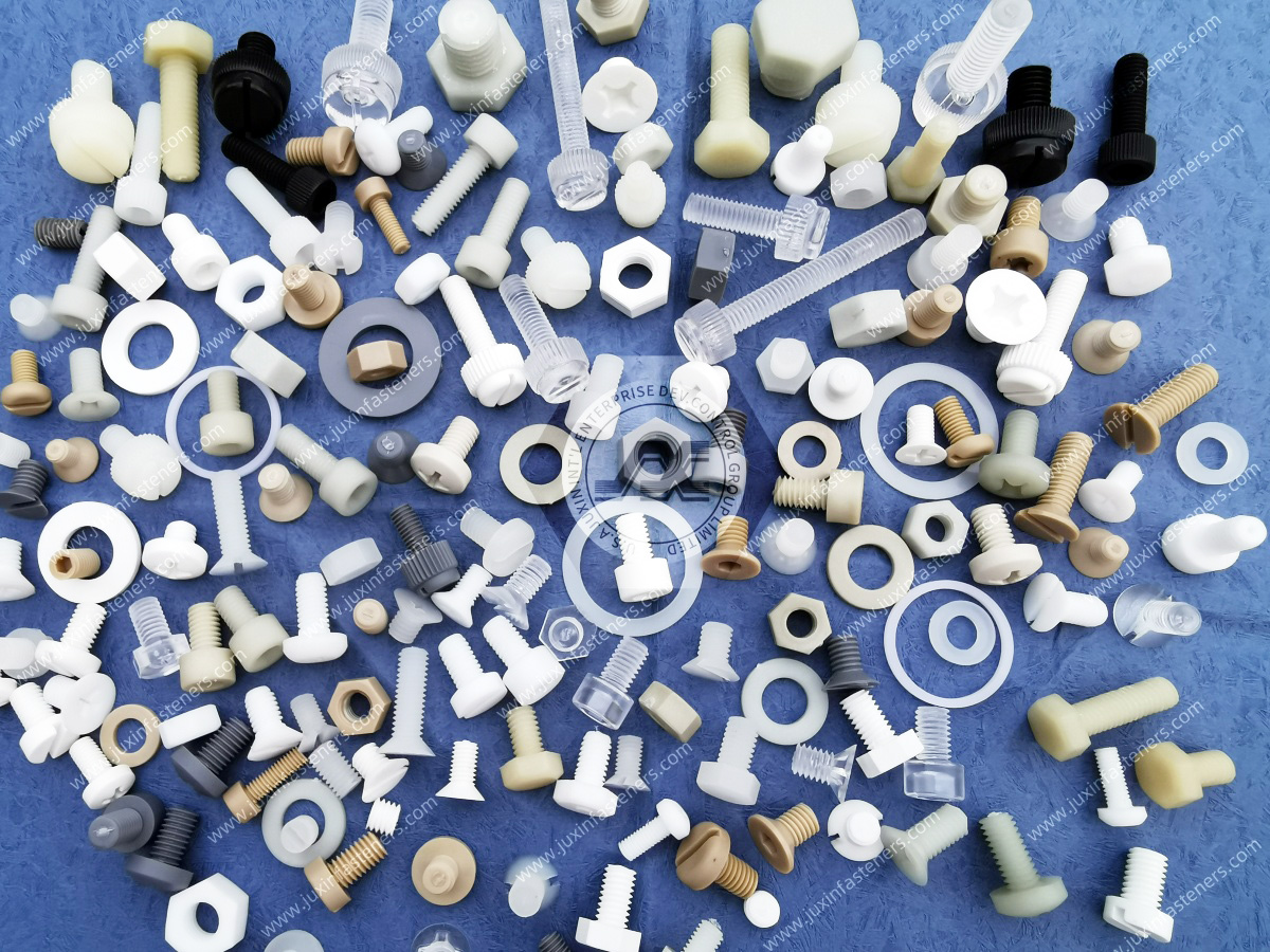
 MORE NEWS

Sep. 27, 2026

Sep. 27, 2026

Sep. 27, 2026
Contact Us
Tel.:
+86 020 8621 0320
+86 020 3121 6067
E-mail:
Technical Support:
Navigation
SEND INQUIREY