
Call Us
+86 136 6007 9809
Call Us
+86 136 6007 9809

Apr. 08, 2026
Automotive clamps perform several very different engineering functions.
Some clamps retain a wiring harness without damaging the cable jacket.
Some secure a rigid tube against vibration.
Some compress a flexible hose against a fitting to create a fluid-sealing interface.
Others connect flanged exhaust or air-handling components.
Calling all of these components simply automotive clamps can hide an important engineering distinction:
Retention, routing, sealing and flange connection are different functions.
A clamp designed to support a fuel or brake tube is not automatically a hose-sealing clamp.
A P-clamp used to route a wiring harness does not perform the same function as a spring hose clamp.
A worm-drive clamp that works on one hose-and-fitting combination may not provide equivalent sealing performance on another.
For automotive engineers, procurement managers and supplier-development teams, clamp selection should therefore begin with:
Joint Function + Hose / Tube / Cable + Diameter + Interface Geometry + Pressure + Temperature + Vibration + Material + Corrosion + Installation + Serviceability + Validation
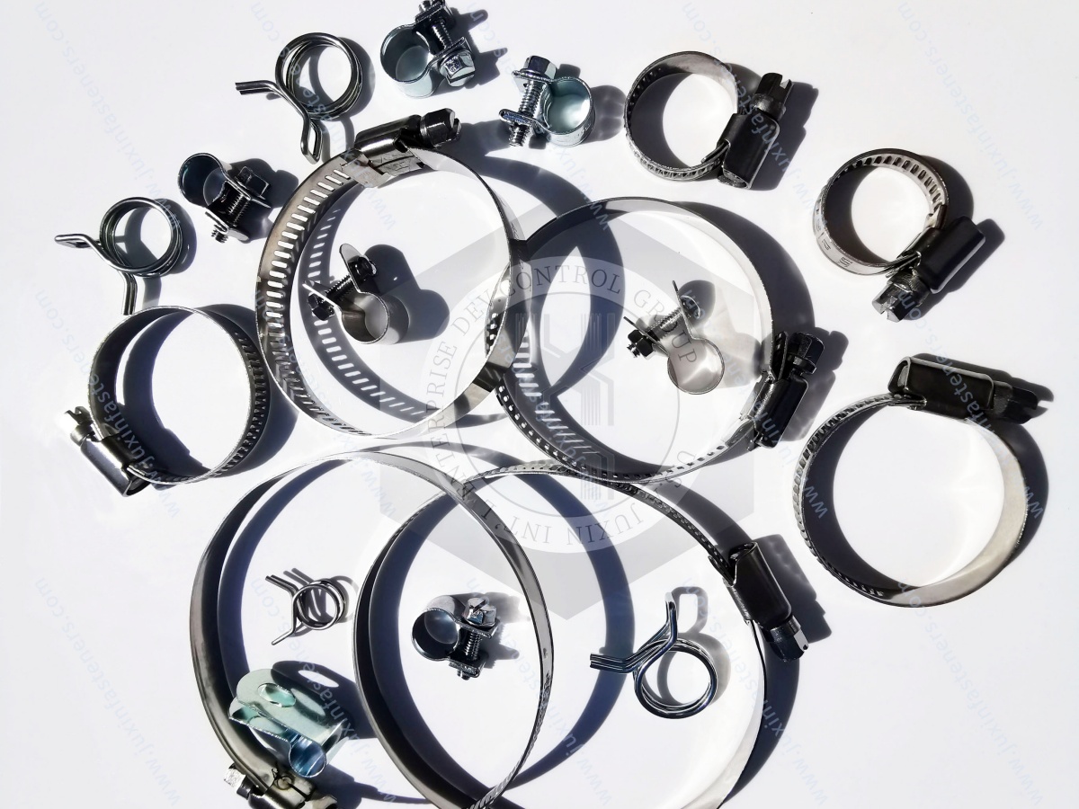
JUXIN FASTENERS supplies and supports standard and drawing-based clamps, clips and fastening components for selected automotive and industrial OEM applications, including:
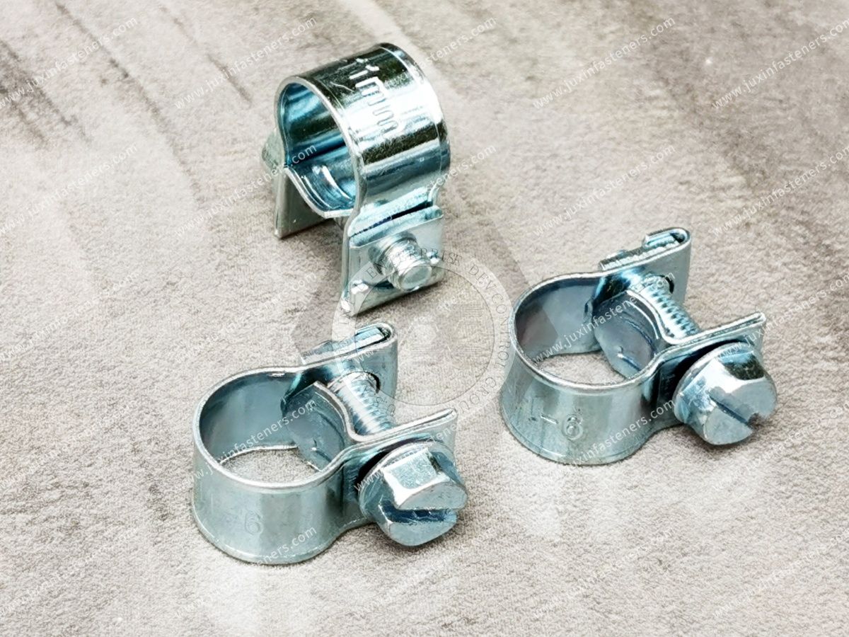
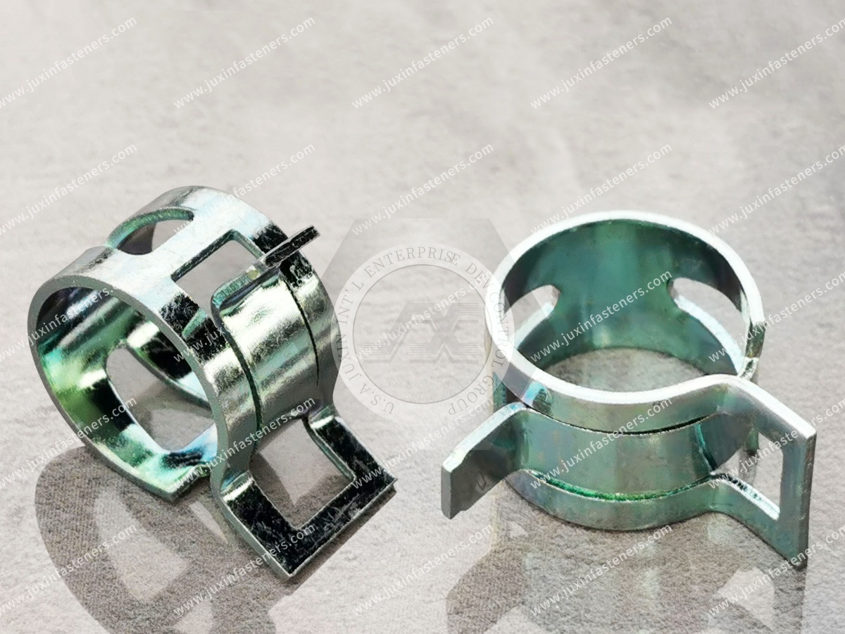
Spring hose clamps
Worm-drive hose clamps
Double-wire clamps
P-clamps
Rubber-lined pipe clamps
Tube-retaining clamps
Wiring harness clamps
Cable clips
Metal retaining clips
V-band clamps
Custom stamped clamps
Custom clips and brackets
Screws, bolts and nuts used with clamp assemblies
Corrosion-resistant fastening components
The correct solution depends on what the clamp must actually do.
| Application | Primary Function | Clamp Technology to Evaluate |
|---|---|---|
| Coolant hose | Maintain hose-to-fitting compression | Spring / constant-tension type hose clamp |
| General service hose | Adjustable radial compression | Worm-drive clamp |
| Small flexible hose | Concentrated controlled retention | Application-specific wire / spring clamp |
| Wiring harness | Routing and abrasion control | P-clamp / cable clamp / clip |
| Rigid tube | Position and vibration management | P-clamp / rubber-lined tube clamp |
| HVAC hose or duct | Retention / sealing depending on interface | Application-specific hose clamp |
| Exhaust flange | Flanged connection | V-band clamp |
| Turbo / charge-air connection | Joint-specific sealing and retention | Application-specific clamp / V-band system |
| Electrical cable routing | Retention without jacket damage | Insulated clamp / polymer clip |
| Custom tube routing | Geometry-specific retention | Drawing-based stamped clamp |
This table is a starting point.
The complete hose, tube, fitting or cable interface determines the final clamp specification.
This distinction should be made before selecting a clamp.
A retaining clamp primarily controls the position of a:
Tube
Pipe
Cable
Wiring harness
Hose
relative to the vehicle structure.
Its engineering requirements can include:
Retention
Vibration isolation
Abrasion prevention
Routing
Clearance control
A sealing hose clamp compresses a hose around a fitting or connection interface.
Its function depends on interaction among:
Clamp + Hose + Fitting + Diameter + Compression + Temperature + Pressure + Installation
Therefore:
Retention Clamp ≠ Sealing Clamp.
A hose may be securely retained while the fluid connection still leaks.
Conversely, excessive clamp force may damage the hose without improving long-term sealing.
Therefore:
Hose Retention ≠ Fluid Sealing.
Leak prevention is a system-level function.
A hose clamp cannot be engineered independently from the hose and fitting.
Important variables include:
Hose inside diameter
Hose outside diameter
Hose wall construction
Elastomer material
Reinforcement
Fitting outside diameter
Fitting surface
Bead geometry
Clamp location
Clamp width
Applied compression
Temperature
Internal pressure
This means that specifying only:
“40 mm automotive hose clamp”
does not fully define the joint.
There is no reliable universal rule such as:
“Clamp diameter should be hose diameter ±5%.”
Clamp sizing depends on:
Clamp design
Working diameter range
Hose outside diameter
Hose compressibility
Fitting geometry
Required compression
Installation method
The manufacturer's functional range and the validated assembly should determine sizing.
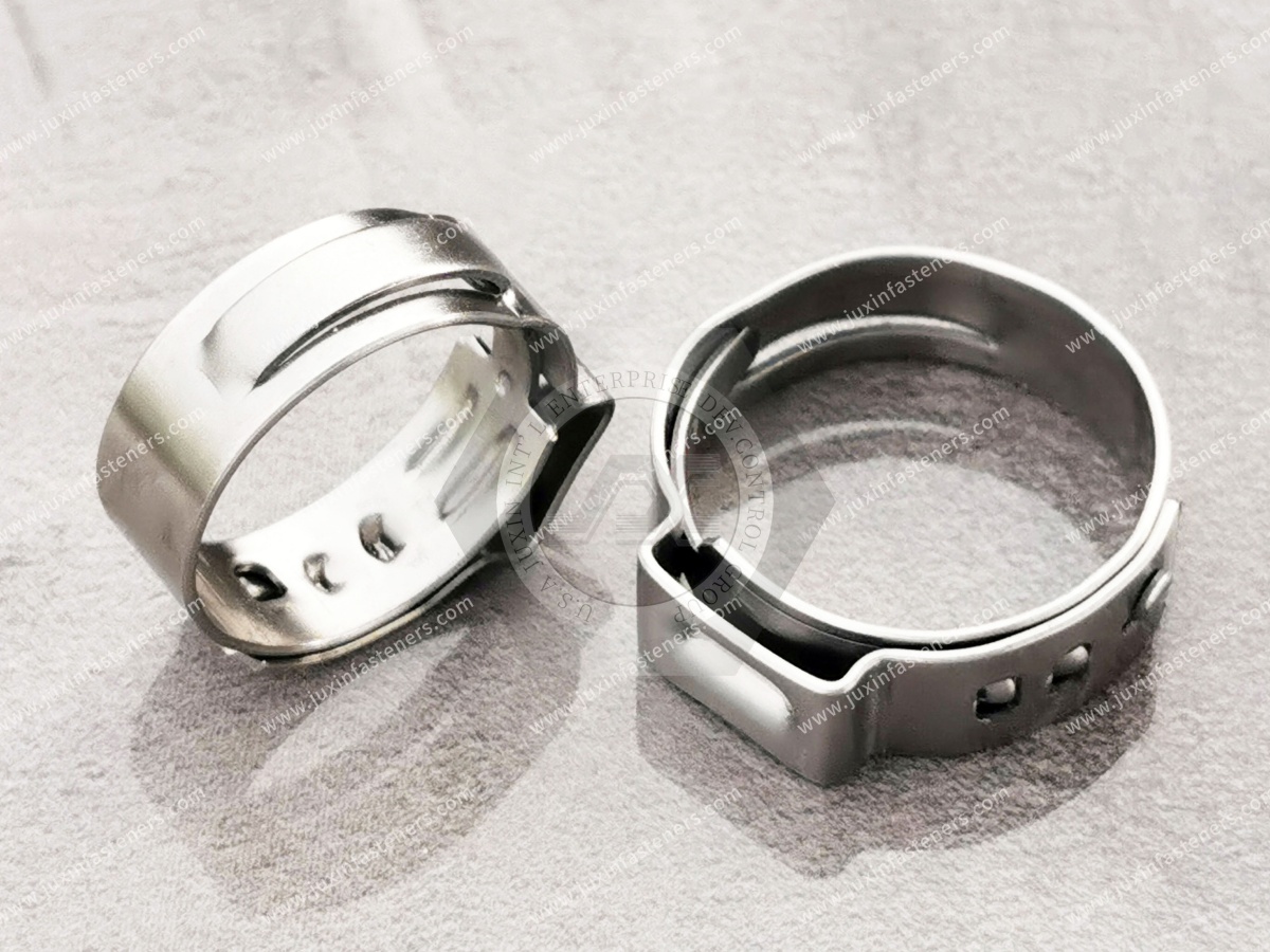
Spring clamps use elastic material behavior to apply radial compression around a hose connection.
They are commonly considered for applications where the hose-and-fitting interface experiences dimensional changes from:
Temperature
Elastomer relaxation
Thermal expansion
Thermal contraction
Potential automotive applications can include selected:
Coolant hoses
Heating circuits
Low-pressure fluid lines
Auxiliary hose systems
The exact suitability depends on the fluid system and OEM specification.
Flexible hoses can change dimensions during operation.
Elastomers can also exhibit:
Creep
Stress relaxation
Compression set
A spring-type clamp can accommodate some dimensional change through its elastic behavior.
This can make it useful where maintaining compression over thermal cycles is important.
But:
Spring Clamp ≠ Guaranteed Constant Sealing Force.
Actual clamp load still changes with:
Diameter
Material
Temperature
Clamp geometry
Hose behavior
One useful way to compare clamp technologies is to ask:
How does the clamp respond when the hose diameter changes?
A more elastic clamp architecture can follow dimensional change differently from a more rigid screw-adjusted clamp.
This matters in automotive systems where:
Cold Start → Operating Temperature → Cool-Down
is repeated thousands of times.
The hose, fitting and clamp may have different thermal expansion characteristics.
During temperature changes:
Hose stiffness changes
Elastomer compression changes
Metal dimensions change
Interface pressure changes
Therefore:
Room-Temperature Clamp Condition ≠ Operating Clamp Condition.
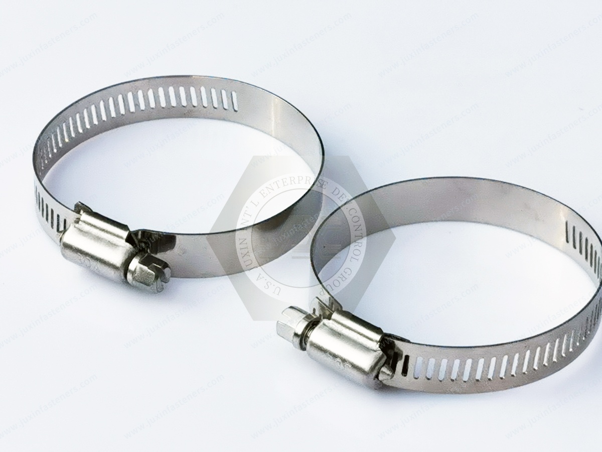
Worm-drive clamps use a screw mechanism to adjust band diameter and compression.
Potential advantages can include:
Wide adjustment range
Familiar installation method
Serviceability
Availability across many diameters
They can be useful in suitable automotive and industrial hose applications.
However:
Adjustable Clamp ≠ Universal Hose Clamp.
The clamp must still match the hose, fitting, pressure and temperature conditions.
Pressure capability cannot be determined by clamp type alone.
A fluid connection depends on:
Hose construction
Fitting design
Clamp
Compression
Pressure
Temperature
Fluid
Dynamic loading
Therefore:
Worm-Drive Clamp ≠ Automatically Suitable for High Pressure.
Pressure-sensitive systems require system-specific engineering and validation.
More screw torque does not automatically improve sealing.
Excessive tightening can cause:
Hose cutting
Localized compression
Band deformation
Screw or housing damage
Fitting deformation
Premature hose failure
Therefore:
More Clamp Torque ≠ Better Seal.
Torque applied to a worm-drive clamp screw is only an installation input.
The resulting hose compression depends on:
Clamp geometry
Friction
Band condition
Screw mechanism
Hose stiffness
Diameter
Therefore:
Clamp Screw Torque ≠ Direct Measurement of Sealing Pressure.
Double-wire clamps use wire elements rather than a broad flat band.
They can be useful in selected hose geometries and packaging conditions.
Potential considerations include:
Hose material
Hose wall thickness
Wire diameter
Clamp range
Local contact pressure
Installation access
Because the contact geometry differs from a band clamp, the hose must be compatible with the localized loading.
A narrow contact area can produce higher local pressure.
That does not automatically mean better long-term sealing.
It can also increase:
Local hose stress
Surface indentation
Material damage
The hose-and-clamp combination must be validated.
P-clamps are commonly used for routing and retaining:
Wiring harnesses
Cables
Rigid tubes
Flexible lines
Small hoses
They typically provide a mechanical attachment point to the vehicle structure while surrounding the routed component.
Potential designs include:
Metal P-clamps
Rubber-lined P-clamps
Polymer-lined clamps
Custom stamped clamps
A P-clamp may surround a tube or hose.
But:
P-Clamp ≠ Hose-Sealing Clamp.
Its primary purpose is generally:
Position control
Routing
Support
Vibration management
rather than creating a fluid seal.
Automotive wiring harnesses require controlled routing.
A clamp should prevent excessive movement without damaging:
Cable insulation
Protective sleeving
Connector leads
Harness coverings
Important design variables include:
Harness diameter
Clamp geometry
Contact surface
Retention force
Edge condition
Vibration
Temperature
Installation location
Excessive clamp force can damage cable protection.
Therefore:
More Clamp Force ≠ Better Harness Retention.
The objective is controlled positioning without unacceptable compression or abrasion.
A harness that moves repeatedly against:
Sheet metal
Brackets
Sharp edges
Adjacent components
can experience wear.
Clamp placement therefore influences more than retention.
It also influences:
Routing path
Clearance
Relative movement
Abrasion risk
An elastomer or polymer lining can provide functions such as:
Surface protection
Vibration isolation
Noise reduction
Reduced metal-to-metal contact
Potential applications include:
Metal tubing
Wiring harnesses
Fluid lines
HVAC lines
But the lining material must match the environment.
A rubber-lined clamp is not fully specified by its metal body.
The liner can be exposed to:
Heat
Oil
Fuel
Coolant
Chemicals
Ozone
Water
Therefore, the liner material should be selected according to actual service conditions.
A rubber liner can reduce direct metal-to-metal contact.
But:
Rubber-Lined Clamp ≠ Vibration-Proof System.
System performance also depends on:
Clamp spacing
Tube mass
Routing
Resonance
Mounting stiffness
Fastener retention
There is no universal clamp-spacing value suitable for every automotive tube or harness.
Spacing can depend on:
Tube diameter
Tube material
Mass
Routing geometry
Vibration environment
Nearby components
OEM requirements
The vehicle-system design should define support locations.
Fuel-system applications can involve demanding:
Fluid compatibility
Temperature
Pressure
Vibration
Corrosion
Regulatory requirements
A general-purpose clamp should not automatically be described as suitable for a fuel-system sealing connection.
Where JUXIN supplies a component for such a project, the customer drawing and system requirements should control the specification.
Rigid brake tubes may use retaining clips or clamps to control:
Position
Clearance
Vibration
Contact with surrounding structures
The clamp does not create the hydraulic seal at the brake-line connection.
Therefore:
Brake Tube Retention ≠ Brake Hydraulic Sealing.
Safety-critical brake-system components require customer-specific engineering and formal validation.
Cooling circuits can expose clamps to:
Repeated heating and cooling
Hose relaxation
Coolant exposure
Engine vibration
Pressure variation
Potential clamp technologies may include spring-type or other application-specific hose clamps.
The complete connection should be evaluated as:
Hose + Fitting + Clamp + Coolant + Temperature + Pressure
Vehicle HVAC systems can include:
Air ducts
Refrigerant lines
Coolant lines
Drain lines
Electrical harnesses
Different locations require different clamp functions.
A duct-retaining clamp should not automatically be treated as a refrigerant-line connection clamp.
V-band clamps are designed around mating flange geometries.
They are used in selected applications such as:
Exhaust connections
Turbocharger-related assemblies
Air-handling systems
Other flanged pipe connections
The V-profile converts clamp tightening into forces acting on the mating flanges.
The clamp cannot be specified independently from:
Flange angle
Flange thickness
Flange diameter
Mating geometry
Band profile
T-bolt
Nut
Installation condition
Therefore:
V-Band Clamp ≠ Standalone Joint Specification.
Excessive tightening can:
Distort flanges
Damage the clamp
Overload the T-bolt
Affect sealing surfaces
The installation requirement should come from the validated joint.
The clamp provides mechanical loading to the flange interface.
Sealing performance also depends on:
Flange geometry
Surface condition
Gasket or sealing architecture where applicable
Alignment
Installation
Therefore:
Clamp Strength ≠ Sealing Performance.
Compact hose-clamp architectures can be useful where packaging space is limited.
Potential considerations include:
Installation tooling
Diameter range
Hose material
Accessibility
Permanent vs serviceable assembly
The appropriate technology should be selected according to the production and service strategy.
Some clamp systems are optimized for rapid production installation.
Others are easier to remove and reinstall during maintenance.
This creates a useful engineering decision:
Production Efficiency vs Field Serviceability
A clamp should not be selected solely for the fastest factory installation if the component requires repeated service.
Potential metallic materials can include:
Carbon steel
Spring steel
Stainless steel
The correct material depends on:
Clamp function
Elastic requirement
Strength
Temperature
Corrosion
Forming process
Cost
Spring clamps depend on controlled elastic behavior.
Their performance can therefore depend on:
Material
Heat treatment
Hardness
Geometry
Forming process
Substituting material without engineering review can change clamp force and fatigue behavior.
Stainless steel may be considered where corrosion resistance is important.
Potential environments include:
Moisture
Road splash
Outdoor exposure
Selected high-temperature locations
But:
Stainless Steel ≠ Corrosion-Proof.
And:
316 ≠ Automatically Better for Every Clamp.
Mechanical spring behavior, manufacturing and environment must also be considered.
Carbon-steel clamps may use engineered coatings to improve corrosion resistance.
Potential systems can include:
Zinc plating
Zinc-nickel
Zinc-flake systems
Customer-specified coatings
The coating can affect more than appearance.
Depending on the clamp design, surface treatment can influence:
Corrosion
Friction
Assembly
Dimensional fit
Spring behavior if process conditions affect the base component
Therefore:
Coating Substitution Can Be an Engineering Change.
A specification such as:
“800-hour salt spray”
should not be treated as a universal requirement for automotive clamps.
Different vehicle locations experience different corrosion severity.
And:
Salt Spray Hours ≠ Field Service Life.
Real service can involve:
Wet/dry cycles
Road salts
Heat
Chemicals
Mechanical wear
Stone impact
Corrosion requirements should follow the customer and application specification.
The clamp may contact:
Aluminum tube
Steel tube
Stainless tube
Coated bracket
Vehicle body
Fastener
Mixed-metal interfaces can introduce galvanic considerations.
Therefore:
Corrosion-Resistant Clamp ≠ Corrosion-Resistant System.
Temperature can affect:
Clamp material
Hose stiffness
Elastomer relaxation
Fitting dimensions
Fluid pressure
This is why a clamp system should be validated across the relevant temperature range rather than only at room temperature.
Elastomeric and polymeric hose materials can change under sustained compression.
Over time, this may reduce interface pressure.
Therefore:
Initial Clamp Tightness ≠ Long-Term Sealing Force.
Clamp architecture should be matched to hose behavior.
Clamps can reduce component movement, but poorly controlled interfaces may still experience micro-motion.
Repeated movement can contribute to:
Abrasion
Fretting
Coating damage
Tube wear
Harness damage
Fatigue
The objective is therefore not simply maximum clamping force.
It is controlled support.
Excessive clamp force can:
Crush a hose
Damage a cable
Deform a thin tube
Accelerate local wear
Therefore:
More Clamp Force ≠ Better Joint.
A P-clamp or pipe clamp must itself be attached to the vehicle structure.
Possible mounting hardware can include:
Bolts
Screws
Weld studs
Rivet nuts
Self-clinching studs
Nuts
The clamp-to-body connection should be engineered separately from the clamp-to-hose or clamp-to-tube interface.
A perfectly selected tube clamp can still fail functionally if the mounting screw loosens.
Therefore the assembly contains at least two interfaces:
Clamp ↔ Tube / Cable
and:
Clamp ↔ Vehicle Structure
Both require appropriate design.
Where a threaded bolt secures the clamp to a bracket:
Torque ≠ Preload.
Friction influences the relationship between installation torque and resulting clamp load.
Coating or lubrication changes can therefore affect mounting performance.
Where vibration requires a locking strategy, engineers may consider:
Prevailing-torque nuts
Thread-locking systems
Other application-specific methods
But:
Locking Feature ≠ Correct Preload.
The base threaded joint still needs correct tightening.
Possible contributors include:
Incorrect clamp size
Incorrect clamp position
Insufficient compression
Excessive compression
Hose relaxation
Fitting geometry
Surface damage
Temperature cycling
Changing to a “stronger clamp” without identifying the mechanism may not solve the problem.
Possible causes include:
Excessive compression
Sharp clamp edges
Incorrect band width
Localized contact pressure
Wrong clamp type
Installation error
Possible causes can include:
Relative movement
Poor clamp spacing
Insufficient isolation
Excessive vibration
Contamination
Possible causes can include:
Sharp edges
Excessive movement
Incorrect routing
Insufficient protective lining
Poor clamp positioning
Potential contributors can include:
Cyclic stress
Incorrect material
Excessive deformation
Temperature
Vibration
Manufacturing defects
This is a threaded-joint issue rather than necessarily a clamp-body issue.
Possible contributors include:
Insufficient preload
Joint movement
Friction variation
Thermal cycling
Incorrect locking strategy
A leakage complaint does not automatically mean:
“Use a stronger hose clamp.”
A vibration complaint does not automatically mean:
“Increase clamp force.”
A corrosion complaint does not automatically mean:
“Change everything to stainless steel.”
Corrective action should follow the actual failure mechanism.
Installation requirements depend on clamp type.
Possible controlled parameters include:
Clamp position
Diameter
Tooling
Installation torque
Closure dimension
Ear deformation
Assembly alignment
There is no universal installation procedure for every clamp.
The statement:
“Always remove all oil before clamp installation”
is too broad.
Some assemblies may have:
Process lubricants
Assembly aids
Customer-specified fluids
Special surface conditions
Installation preparation should follow the validated hose-system specification.
Leak testing may be appropriate for a fluid connection.
But the test method depends on:
System
Pressure
Fluid
Safety requirement
Customer specification
A generic air or water leak test should not be prescribed for every automotive clamp assembly.
Depending on design, clamp manufacturing can involve:
Stamping
Wire forming
Roll forming
Bending
Welding
Heat treatment
Surface treatment
Rubber or polymer lining assembly
Custom clamp development should consider both component geometry and production process.
For a spring clamp, functional force depends on more than dimensions.
It can also depend on:
Material
Heat treatment
Hardness
Forming
Residual stress
Therefore:
Same Dimensions ≠ Same Spring Performance.
Two spring clamps can look geometrically similar while generating different forces.
Depending on the application, functional validation may include:
Clamp-force measurement
Diameter-force behavior
Installation behavior
Fatigue testing
Corrosion testing
Hose-joint validation
The exact test plan should follow the customer requirement.
Depending on product type, quality control may include:
Material verification
Dimensional inspection
Surface inspection
Hardness testing where relevant
Clamp-force testing
Spring-function testing
Coating inspection
Corrosion testing where specified
Functional fit testing
Not every clamp requires every test.
The control plan should match the component function.
A clamp can pass its component inspection and still leak when assembled with the hose and fitting.
Therefore:
Clamp Drawing Compliance ≠ Hose Joint Validation.
Production-representative components can provide more useful validation.
A standalone clamp vibration test may provide limited information if the real failure depends on:
Tube routing
Clamp spacing
Hose mass
Bracket stiffness
Vehicle excitation
Where vibration performance matters, the relevant assembly should be considered.
Standard clamps do not fit every vehicle architecture.
Custom designs may be required for:
Unique tube routing
Restricted packaging space
Multiple-line retention
Integrated mounting tabs
Special diameters
Special liners
Automated installation
JUXIN FASTENERS can review customer drawings for suitable clamp, clip and fastening-component projects.
Drawing-based retaining hardware can include:
Custom P-clamps
Tube clamps
Cable clamps
Stamped retaining clips
Brackets
Engineering review may consider:
Geometry
Material
Thickness
Bend radius
Mounting hole
Liner
Surface treatment
Annual volume
For a custom hose-clamp project, engineering should define:
Hose OD range
Fitting geometry
Working diameter
Clamp type
Material
Temperature
Pressure
Fluid
Required clamp behavior
Installation method
The hose and fitting drawings are highly valuable.
Prototype geometry may sometimes be produced through a different manufacturing route.
But production validation should use representative:
Material
Heat treatment
Surface treatment
Forming process
where these affect clamp function.
Supplier-development teams should evaluate more than whether a supplier can manufacture the correct diameter.
Important controls may include:
Drawing revision
Material
Heat treatment
Functional force
Surface treatment
Liner material
Dimensions
Inspection
Traceability
Change control
Second-source approval should compare:
Geometry
Material
Hardness where relevant
Heat treatment
Working range
Clamp-force behavior
Surface treatment
Liner
Installation
Functional performance
Therefore:
Same Dimensions ≠ Functional Equivalence.
For spring-type clamps, comparing only:
Diameter
Width
Thickness
may be insufficient.
Functional behavior can also depend on:
Material
Heat treatment
Forming process
Spring characteristics
A second source should be functionally validated.
Where the clamp contributes to sealing, qualification should include the actual or representative:
Hose + Fitting + Clamp
because clamp component inspection alone does not prove sealing performance.
Clamp sourcing should consider more than unit price.
A useful model is:
Total Installed Cost = Clamp Price + Mounting Hardware + Installation + Tooling + Inspection + Rework + Scrap + Leak Risk + Maintenance + Logistics + Supply Risk
A slightly more expensive clamp may reduce installation time or field failures.
An unnecessarily complex clamp may add cost without functional benefit.
For high-volume automotive production, clamp design can affect:
Feeding
Orientation
Tool access
Installation speed
Ergonomics
Mistake-proofing
Automation
Production engineering should therefore be involved in clamp selection.
Procurement may want to standardize one clamp across multiple applications.
This can reduce:
SKU count
Inventory
Purchasing complexity
But excessive standardization can create poor technical matches.
The correct balance is:
Standardize Where Function Is Equivalent; Customize Where the Interface Requires It.
For an effective technical and commercial review, provide:
2D drawing
3D model where available
Part number
Drawing revision
Application
Clamp function
Hose / tube / cable type
Hose or tube material
Outside diameter
Fitting geometry where relevant
Pressure where relevant
Fluid where relevant
Service temperature
Vibration requirement
Clamp material
Liner material where applicable
Surface treatment
Installation method
Annual volume
Sample quantity
Validation requirements
Applicable ISO, DIN, EN, SAE, ASTM, ASME/ANSI or customer specification
Provide:
Hose drawing
Hose material
Hose OD range
Hose wall construction
Fitting drawing
Fitting OD
Bead geometry
Fluid
Pressure
Temperature range
Required installation condition
Leak-test requirement
Do not specify only:
“40 mm hose clamp.”
Provide:
Tube / harness diameter
Routing geometry
Clamp spacing where defined
Mounting interface
Vibration environment
Liner requirement
Temperature
Chemical exposure
Retention requirement
Provide:
Flange drawing
Flange diameter
Flange angle / profile
Mating geometry
Clamp diameter
Band profile
T-bolt requirement
Nut requirement
Temperature
Sealing architecture
Installation requirement
Do not qualify a V-band clamp independently from the flange system.
A controlled development process can follow:
Application → Clamp Function → Hose / Tube / Cable → Interface Geometry → Material → Environment → Clamp Technology
→ Drawing Review → Sample → Installation Trial → Functional Validation → Approval → Production
For hose-sealing applications:
Hose + Fitting + Clamp → Compression / Installation → Pressure & Temperature → Leak Validation → Thermal Cycling / Durability Where Required → Production Approval
For routing applications:
Tube / Harness + Clamp + Mounting Point → Retention → Clearance → Vibration / Abrasion Review → Production Approval
This page should function as the dedicated Automotive Clamps / Hose Clamps / Pipe & Harness Retention resource.
Recommended internal links include:
Automotive Fastener Selection Guide → overall automotive fastening technology selection
Automotive Threaded Fasteners → mounting-bolt preload, friction and locking
Automotive Fastener Quality Control → inspection and supplier qualification
Lightweight Automotive Fasteners → automotive material selection
Automotive Self-Tapping Screws → clamp and bracket mounting into metal or plastic
Stainless Steel Fasteners → corrosion-resistant stainless components
Fastener Surface Treatment & Coating Selection → corrosion and friction
Zinc-Nickel Coated Fasteners → automotive corrosion protection
Fasteners for Aluminum → mixed-metal automotive assemblies
Custom Fastener Manufacturing → drawing-based manufacturing and DFM
Fastener Failure Modes → loosening, corrosion, fatigue and assembly failures
Use the existing indexed JUXIN FASTENERS URL when implementing these internal links.
A hose clamp may compress a flexible hose against a fitting and contribute to sealing.
A pipe or tube clamp often primarily supports, routes or retains the tube. Their engineering functions are different.
There is no universal best clamp. Selection depends on hose material, fitting geometry, diameter, pressure, temperature, fluid, thermal cycling and service requirements.
Not universally. Spring-type clamps can respond differently to hose dimensional changes, while worm-drive clamps provide adjustable installation.
The correct design depends on the hose system.
They can accommodate dimensional changes through elastic behavior, but clamp force is not literally constant under all diameters and temperatures.
Not automatically. Pressure capability depends on the complete hose, fitting and clamp system.
Not necessarily. Excessive tightening can damage the hose, clamp or fitting. More torque does not automatically create a better seal.
Use the clamp's validated working range together with the actual hose OD, fitting geometry and required compression.
A universal percentage rule should not be used.
P-clamps are commonly used to route and retain tubes, hoses, cables and wiring harnesses.
They normally provide support rather than fluid sealing.
A suitable lining can help protect the routed component, reduce metal-to-metal contact and provide vibration isolation. Liner material must be compatible with the environment.
No. Stainless steel can provide useful corrosion resistance, but mechanical properties, spring behavior, galvanic interaction, temperature and cost must also be considered.
There is no universal number for every clamp. Corrosion requirements should follow the specific vehicle location and OEM specification.
Possible causes include incorrect sizing, clamp position, hose relaxation, fitting geometry, insufficient or excessive compression, temperature cycling and installation errors.
Potential causes include excessive clamp force, sharp edges, poor routing, vibration, abrasion or an unsuitable liner.
No. Sealing also depends on flange geometry, alignment, surface condition and the complete connection architecture.
Compare geometry, material, heat treatment, spring behavior, surface treatment and installation performance, then perform functional validation where required.
Provide the clamp drawing, application, hose/tube/cable information, mating geometry, diameter, material, temperature,
pressure or fluid where relevant, surface treatment, installation method, annual volume and validation requirements.
The most important principle in automotive clamp engineering is:
Clamp Performance Belongs to the Interface.
For a hose-sealing connection:
Clamp + Hose + Fitting + Compression + Pressure + Temperature + Installation
determine performance.
For a tube or wiring-harness support:
Clamp + Tube / Cable + Liner + Mounting Point + Routing + Vibration + Environment
determine performance.
This means:
Retention Clamp ≠ Sealing Clamp
Hose Retention ≠ Fluid Sealing
More Clamp Force ≠ Better Joint
Clamp Screw Torque ≠ Sealing Pressure
Spring Clamp ≠ Guaranteed Constant Force
Corrosion-Resistant Clamp ≠ Corrosion-Resistant Assembly
Same Dimensions ≠ Functional Equivalence
JUXIN FASTENERS supports selected automotive and industrial OEM clamp and fastening projects including:
Spring hose clamps
Worm-drive hose clamps
Double-wire clamps
P-clamps
Rubber-lined pipe clamps
Wiring harness clamps
Cable clips
Tube-retaining clips
V-band clamps
Custom stamped clamps
Custom retaining clips
Clamp mounting screws, bolts and nuts
Drawing-based fastening components
If you are developing a hose connection, tube-routing system, wiring harness, HVAC assembly, cooling circuit,
exhaust connection or custom retaining component, send the technical package for engineering and commercial review.
For an effective RFQ, provide:
2D Drawing + 3D Model + Part / Revision + Application + Clamp Function + Hose / Tube / Cable + Diameter + Mating Interface + Material
+ Temperature + Surface Treatment + Installation Method + Annual Volume
Where relevant, also provide:
Fluid + Pressure + Hose Material + Fitting Geometry + Thermal Cycling + Vibration + Clamp Force Requirement + Liner Material + Leak Requirement + Functional Validation
JUXIN FASTENERS
Automotive Clamps | Automotive Hose Clamps | Pipe Clamps | P-Clamps | Wiring Harness Clamps | V-Band Clamps | Custom OEM Clamps
Email: info@juxinfasteners.com
Website: www.juxinfasteners.com
Contact Us
Tel.:
+86 020 8621 0320
+86 020 3121 6067
E-mail:
Technical Support:
Navigation
SEND INQUIREY



