
Call Us
+86 136 6007 9809
Call Us
+86 136 6007 9809

Sep. 21, 2026
Modern automotive and electric vehicle manufacturing requires threaded fastening points that can support rapid assembly, dimensional variation,
corrosion protection, repeated service access and long-term operation under vibration and thermal cycling.
For suitable sheet-metal edges and flanges, automotive clip-on nuts provide a practical alternative to welded or permanently installed threaded attachment systems.
These spring fasteners—including U-nuts, J-nuts and other edge-mounted clip nuts—can establish threaded attachment points without welding, tapping or permanent press installation into the panel.
Typical applications include:
body-panel brackets;
underbody shields;
splash shields;
under-hood service covers;
auxiliary brackets;
interior support panels;
access covers;
electrical and electronic equipment covers;
non-structural serviceable sheet-metal assemblies.
However, an automotive clip-on nut should never be selected only because the thread size matches the mating screw.
The complete fastening system includes:
Clip Geometry + Panel Edge + Panel Thickness + Hole Position + Mating Screw + Installation Process + Surface Finish + Service Environment
For automotive design engineers and Tier-1/Tier-2 sourcing teams, each of these interfaces matters.
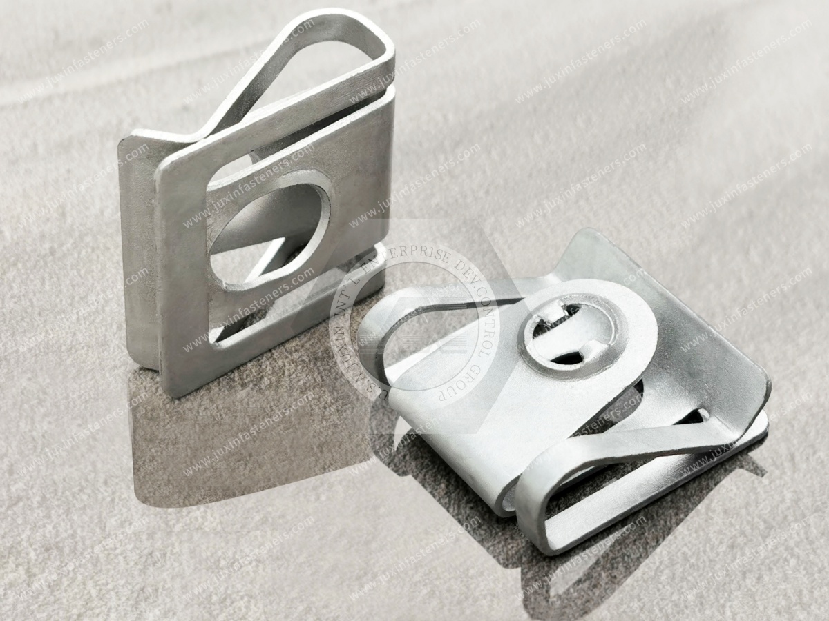
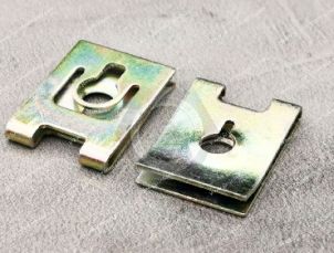
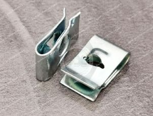
An automotive clip-on nut is an edge-mounted spring fastener designed to attach to a sheet-metal flange or panel edge and provide a fastening interface for a mating screw.
Depending on the design, it may be called:
automotive U-nut;
automotive J-nut;
spring nut;
clip nut;
edge clip nut;
speed nut;
spring steel clip;
body panel clip nut.
Commercial terminology varies, so sourcing should ultimately be controlled by the drawing, dimensions and application requirements rather than the product name alone.
The spring body engages the panel edge and helps retain the fastener in position before final screw installation.
A simplified assembly is:
Panel Edge → Clip-On Nut → Panel / Mating Component Hole → Screw
During final assembly, the mating screw engages the threaded or formed fastening feature.
The completed joint then depends on:
screw engagement;
panel geometry;
clip geometry;
tightening process;
joint stack-up.
This creates an important distinction:
Clip Retention Before Assembly ≠ Final Joint Clamp Performance
Clip-on nuts can solve several production and service problems simultaneously.
Potential advantages include:
no welding at the clip installation point;
no tapping of thin sheet;
rapid installation onto suitable panel edges;
potential post-finish installation;
replaceability in suitable service applications;
accommodation of certain manufacturing tolerances depending on design;
compatibility with manual or automated assembly processes.
Their value is therefore not simply the price of the fastener.
The larger question is how the fastener affects the vehicle manufacturing and service process.
Weld nuts remain important in automotive manufacturing, particularly where the structural design and manufacturing route require welded threaded attachment points.
Clip-on nuts solve a different problem.
They can be attractive when:
the fastening point is near an accessible edge;
welding is unnecessary or undesirable;
post-finish installation is beneficial;
field replacement is valuable;
the assembly is serviceable;
tolerance accommodation is required by the selected clip architecture.
Therefore:
Clip-On Nut ≠ Universal Weld Nut Replacement
The correct technology depends on the actual joint.
For broader technology selection, see Sheet-Metal Fastener Selection: Clip-On vs Weld, Clinch & Rivet Nuts.
Automotive clip-on nuts are particularly useful in appropriate non-structural and serviceable assemblies.
Typical areas can include:
body-panel brackets;
interior support panels;
instrument-panel-related brackets;
center-console structures;
under-hood covers;
splash shields;
underbody shields;
service access panels;
auxiliary electronic covers;
HVAC-related covers and brackets;
wiring-related support brackets;
trim-support structures;
removable protective panels.
The exact application should always be validated against the vehicle manufacturer's requirements.
Stamped sheet-metal brackets often provide ideal geometry for edge-mounted spring fasteners.
The clip can be installed onto:
flange;
return edge;
stamped tab;
bracket edge.
The screw then connects another component to the bracket.
Important variables include:
panel thickness;
flange width;
hole setback;
thread location;
mating-part alignment.
Underbody assemblies can require removable fasteners for:
shields;
covers;
splash protection;
service access.
Clip-on nuts can be useful where the mating sheet-metal architecture provides an appropriate edge.
However, the underbody environment can expose components to:
water;
road contamination;
de-icing salts;
temperature variation;
vibration;
impact from debris.
Material and surface protection therefore require application-specific evaluation.
Under-hood areas may include:
electronics covers;
auxiliary brackets;
service shields;
air-management components;
equipment covers.
Serviceability can be important because these components may need removal during inspection or repair.
An accessible clip-on nut can offer a useful maintenance advantage if a fastening thread becomes damaged.
Vehicle interiors contain numerous sheet-metal and mixed-material support assemblies.
Clip-on nuts may be used where appropriate for:
dashboard-related brackets;
console structures;
interior covers;
trim-support components;
serviceable interior panels.
However, noise, vibration and harshness requirements belong to the complete assembly.
The clip should not automatically be represented as a noise-damping component.
Electric vehicles contain additional:
electronic modules;
thermal-management equipment;
wiring systems;
protective covers;
auxiliary brackets.
Clip-on nuts may support suitable serviceable sheet-metal attachment points in these systems.
However:
EV Application ≠ Automatic Battery Structural Application
Battery enclosure structures, high-voltage systems and crash-critical assemblies may require dedicated fastening architectures and customer-specific validation.
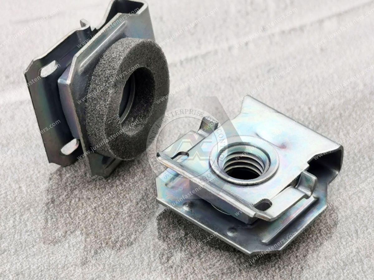
Automotive fastening systems operate in a dynamic environment.
Vehicles experience:
road-induced vibration;
cyclic structural movement;
thermal cycling;
moisture;
contamination;
repeated service operations.
At the same time, production lines demand:
rapid installation;
repeatable screw engagement;
low rework;
predictable component presentation;
consistent fit.
The correct automotive clip-on nut must therefore support both:
Manufacturing Performance
and:
Service Performance
Not in the same sense as a dedicated vibration damper.
The spring body provides elastic engagement with the panel.
That helps maintain clip retention before and during assembly.
However:
Spring Clip Elasticity ≠ Vibration Damping
The final joint's behavior under road vibration depends on:
screw preload;
thread engagement;
joint stiffness;
transverse movement;
friction;
panel stiffness;
thermal cycling;
locking strategy where required.
A clip-on nut should not automatically be marketed as a vibration absorber.
No fastener should be called vibration-proof without defined application validation.
A clip-on nut can perform reliably in automotive environments when:
the clip is correctly selected;
panel geometry is controlled;
screw engagement is appropriate;
assembly parameters are validated;
the complete joint satisfies vehicle requirements.
For more detailed vibration-related selection considerations, see Strong-Grip Clip-On Nuts for Vibration-Resistant Assemblies.
This distinction is especially important in automotive engineering.
The ability of the spring fastener to remain attached to the panel before and during screw assembly.
The mechanical performance of the completed:
Screw + Clip Nut + Panel + Mating Component
system.
A clip that stays firmly on the panel is not automatically a strong final joint.
Likewise, high clip-retention force does not establish the final joint clamp condition.
Automotive body and bracket components are produced from controlled sheet thicknesses, but the clip interacts with the actual finished panel.
Relevant variables can include:
base metal thickness;
material tolerance;
plating;
paint;
powder coating;
e-coat;
adhesive or sealant where present;
stacked sheet interfaces;
local forming.
Therefore:
Nominal Sheet Thickness ≠ Always Effective Installed Thickness
The clip should be evaluated against the actual interface it will grip.
For detailed guidance, see Panel Thickness Selection Guide.
If the panel is below the intended grip condition or the clip geometry is unsuitable, possible symptoms include:
clip migration;
clip rotation;
fastener falling off during handling;
thread misalignment;
screw cross-threading.
These problems can create line stoppages even before the vehicle joint is completed.
If the panel is too thick for the selected clip or installation requires excessive deformation, potential problems can include:
difficult installation;
permanent clip deformation;
coating damage;
panel marking;
poor thread alignment;
clip fracture in severe cases.
More retention force is therefore not automatically better.
For an edge-mounted clip, the distance between the panel edge and screw-hole center must match the clip geometry.
This dimension is often referred to as:
Hole Setback
or:
Edge-to-Hole Distance
If the clip's thread center does not align with the panel hole, the screw may enter at an angle.
Possible consequences include:
cross-threading;
abnormal rundown torque;
clip movement;
incomplete seating;
assembly rejection.
A vehicle assembly may contain:
Body Panel → Bracket → Clip Nut → Cover → Screw
Each component has dimensional tolerances.
The final screw must still locate and engage correctly.
This means fastener selection should consider the entire tolerance chain.
Some clip architectures provide limited positional accommodation.
Others are comparatively fixed.
Therefore:
Clip-On Nut ≠ Automatically Floating Nut
Where positional movement is required, the drawing should define or validate the required accommodation.
Do not assume it from the generic product family.
These are not the same condition.
Controlled positional accommodation can help assembly.
Uncontrolled movement can cause:
misalignment;
rattling before assembly;
inconsistent screw engagement.
The design objective is:
Required Adjustment Without Uncontrolled Migration
Powered screwdrivers can engage fasteners rapidly.
If the screw axis does not align with the clip thread, the tool may force the screw into the fastener.
This can create:
cross-threading;
thread damage;
abnormal torque;
clip displacement.
Automation therefore increases the importance of:
hole position;
clip location;
driver alignment;
thread compatibility.
Automotive clip-on nuts may use metric or inch thread systems depending on the vehicle program and market.
For metric programs, specify:
nominal diameter;
pitch;
mating screw requirement.
Do not simply state:
M6
when the drawing should define the actual thread requirement.
For broader metric selection, see Metric Clip-On Nuts Selection Guide.
Two automotive clip-on nuts can both have the same thread size while differing in:
grip range;
throat depth;
hole setback;
width;
length;
spring geometry;
material;
finish.
Therefore:
Same Thread ≠ Same Automotive Clip
Spring fasteners require a material condition capable of providing the required elastic behavior.
Potential material systems include specification-controlled:
carbon spring steel;
other spring steels;
stainless spring materials where appropriate.
Material should be controlled through the applicable:
customer drawing;
product specification;
recognized material standard;
approved supplier requirement.
A local spring-steel designation should not automatically be treated as equivalent to another international grade.
For global automotive programs, material equivalence should consider:
chemistry;
mechanical properties;
heat-treatment condition;
thickness;
forming behavior;
spring performance.
A familiar grade name alone is insufficient.
Where heat treatment is part of the manufacturing route, its purpose is to achieve the required final material condition.
Relevant product behavior can include:
elastic recovery;
strength;
toughness;
resistance to permanent deformation.
Higher hardness alone does not automatically mean better automotive clip performance.
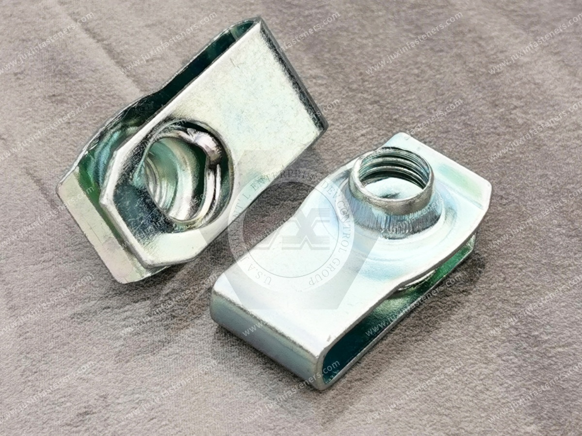
Automotive fasteners can encounter very different environments depending on vehicle location.
An interior bracket and an underbody shield clip do not necessarily require the same corrosion-protection system.
Potential coating systems may include appropriate:
zinc-based electroplating;
zinc-alloy electroplating;
conversion coatings;
sealers;
top coats;
other customer-specified systems.
Selection should follow the vehicle program and customer specification.
ISO 4042 provides requirements for electroplated coating systems on fasteners.
Its scope includes non-threaded fasteners such as clips as well as threaded fasteners.
The standard addresses zinc and zinc-alloy coating systems among other electroplated systems and includes requirements and recommendations related to minimizing hydrogen-embrittlement risk.
For automotive sourcing, however:
ISO 4042 Compliance ≠ Complete Vehicle Corrosion Specification
OEM or Tier customer requirements may define additional:
coating system;
thickness;
appearance;
friction;
corrosion testing;
cyclic testing;
documentation.
Zinc-nickel is one of the coating systems covered within ISO 4042.
It can be considered where required by the applicable customer specification.
However, JUXIN FASTENERS should not assign a universal corrosion-life claim simply from the coating name.
Performance depends on the complete coating system and test requirement.
For susceptible high-strength or hardened steel components, manufacturing and electroplating processes require appropriate consideration of hydrogen embrittlement.
Risk depends on factors including:
material;
hardness/strength condition;
manufacturing route;
surface preparation;
coating process;
applied stress.
There is no universal post-plating bake recipe that should be copied into every automotive clip specification.
The applicable material, process and customer requirements should control the mitigation strategy.
ISO 9227 specifies laboratory salt-spray test methods.
It can be useful for assessing the quality of corrosion-protection systems and identifying coating discontinuities.
However:
Salt Spray Hours ≠ Vehicle Service Life
ISO 9227 does not prescribe one universal exposure duration for automotive clip-on nuts.
The required:
test method;
exposure time;
evaluation criteria;
acceptable corrosion condition
must come from the applicable product or customer specification.
A coating that survives more hours in one laboratory test should not automatically be described as providing proportionally longer vehicle life.
Actual automotive corrosion exposure can involve:
wet/dry cycling;
salt;
temperature variation;
contamination;
coating damage;
galvanic interaction.
For some applications, OEMs may specify cyclic corrosion testing rather than relying only on neutral salt spray.
One useful procurement improvement is to classify the actual installation zone before specifying the finish.
Potential exposure may be comparatively controlled, depending on location.
Possible conditions include:
heat;
humidity;
fluids;
thermal cycling.
Potential exposure can include:
water;
road salt;
debris;
contamination;
repeated wet/dry cycles.
Therefore:
Automotive Application ≠ One Universal Coating Specification
Where different metallic materials contact each other in the presence of an electrolyte, galvanic interaction may become relevant.
The complete interface can include:
clip material;
panel material;
panel coating;
screw material;
screw coating.
Corrosion engineering should therefore evaluate the joint as a system.
This is particularly important for spring clips.
The clip grips the finished panel.
If the surface system materially changes effective thickness, it can influence:
insertion force;
retention;
coating damage;
clip deformation.
This is one reason the RFQ should include the finished panel condition.
Many automotive clip-on nut designs can be installed after body or component finishing.
This can avoid exposing the clip thread to certain upstream coating operations.
However, post-finish installation introduces its own considerations:
scratching;
coating indentation;
clip insertion force;
effective grip thickness.
The complete process should be validated.
High-volume vehicle production may use:
manual installation;
semi-automatic installation;
automated feeding;
dedicated clip installation equipment.
The clip design should be evaluated for the actual assembly method.
Automation-related considerations can include:
part orientation;
feeding geometry;
installation direction;
insertion force;
positional repeatability;
packaging.
For manual assembly, bulk packaging may be acceptable depending on customer requirements.
Automated feeding can impose additional requirements relating to:
clip geometry;
tangling;
orientation;
contamination;
packaging format.
Therefore packaging should be treated as part of the production requirement rather than only a logistics detail.
Clip-on nuts can be particularly valuable on components that may require removal during vehicle service.
If a replaceable clip thread is damaged, an accessible clip may be removed and replaced without welding.
This can be useful for appropriate:
service covers;
shields;
access panels;
auxiliary brackets.
However, the panel itself must remain suitable for reuse.
A serviceable panel may be removed multiple times during vehicle life.
The design should therefore consider:
screw thread condition;
clip thread condition;
panel-edge condition;
coating wear;
installation/removal method.
Do not assume unlimited reuse without validation.
Noise, vibration and harshness—NVH—is a vehicle-system characteristic.
A clip-on nut can help hold an assembly in its intended position, but it should not automatically be described as an NVH solution.
Squeaks and rattles can originate from:
panel movement;
insufficient clamp;
contact between components;
tolerance stack-up;
material interfaces.
Therefore:
Clip-On Nut ≠ Automatic Anti-Rattle Device
Generic clip-on nuts should not automatically be selected for:
crash-critical structures;
primary suspension mounting;
steering attachment;
braking attachment;
seat-belt anchorage;
other safety-critical load paths.
Such applications require the applicable vehicle engineering requirements and dedicated validation.
This distinction should be made early in the design process.
Clip-on nuts may be strong candidates where geometry and load requirements are suitable.
The complete structural fastening strategy must be validated to the relevant vehicle program requirements.
Do not select a generic clip based solely on convenience.
Potential production and service issues include:
clip migration;
clip falling off before assembly;
hole misalignment;
cross-threading;
thread stripping;
panel distortion;
coating damage;
corrosion;
service loosening.
For systematic troubleshooting, see Clip-On Nut Failure Analysis.
Possible contributors include:
incorrect grip range;
unsuitable spring geometry;
panel variation;
coating thickness;
incorrect installation.
Possible contributors include:
hole misalignment;
wrong screw;
driver angle;
clip movement;
damaged thread.
Possible contributors include:
excessive grip;
wrong clip profile;
excessive installation force;
sensitive coating system.
Possible contributors can include:
inadequate initial clamp;
settlement;
transverse vibration;
thermal cycling;
unsuitable locking strategy.
Do not automatically attribute service loosening to the clip's panel-retention legs.
| Engineering Requirement | Clip-On Nut Consideration |
|---|---|
| Thread near panel edge | Strong candidate |
| No welding desired | Strong candidate |
| Post-finish installation | Often advantageous |
| Easy field replacement | Often advantageous |
| Limited backside access | Possible where edge remains accessible |
| Mid-panel thread far from edge | Another technology may be better |
| Tolerance accommodation | Available in selected designs |
| High corrosion exposure | Finish must match program requirement |
| Road vibration | Complete joint must be validated |
| High-speed automated assembly | Geometry, feeding and screw alignment matter |
| Structural/crash load | Dedicated structural validation required |
| Repeated service | Thread and panel durability must be evaluated |
Is the fastener:
interior;
under-hood;
underbody;
exterior;
service-access related?
Specify:
material;
base thickness;
tolerance;
coating;
finished thickness.
Specify:
flange width;
edge radius;
hole setback;
available throat depth.
Specify:
thread diameter;
pitch;
screw length;
head style;
material/property requirements;
coating where relevant.
Is installation:
manual;
semi-automatic;
automated?
Consider:
clamp requirement;
vibration;
thermal cycling;
service access;
number of expected service cycles.
Specify:
moisture;
salt;
temperature;
chemical exposure;
customer corrosion requirements.
Evaluate:
U-nut;
J-nut;
enclosed hex clip;
tapping-screw clip;
another spring-fastener configuration.
Test the actual:
Clip + Finished Panel + Screw + Assembly Process
After validation, control:
drawing;
material;
finish;
critical dimensions;
inspection requirements;
packaging;
change-management requirements.
Both can be useful edge-mounted fasteners.
The correct choice depends on:
panel geometry;
access;
clip profile;
thread position;
assembly direction.
For detailed geometry selection, see U-Nuts vs J-Nuts Geometry.
Consider a clip-on nut when:
edge access exists;
serviceability matters;
welding is unnecessary;
post-finish installation is beneficial.
Consider a weld nut where:
the design requires a welded threaded attachment;
the manufacturing route supports controlled welding;
structural and process requirements favor that architecture.
Neither technology is universally superior.
A clip-on nut generally requires a suitable panel edge.
A blind rivet nut can create a thread in a prepared hole away from the edge and can be installed from one accessible side.
Therefore:
Edge Thread → Clip-On Nut May Be Efficient
Mid-Panel Blind Thread → Rivet Nut May Be More Appropriate
For broader comparison, see Sheet-Metal Fastener Selection Guide.
A self-clinching nut is mechanically installed into an appropriate prepared hole in suitable sheet.
A clip-on nut attaches to an edge.
The decision depends on:
thread location;
parent sheet;
installation equipment;
serviceability;
manufacturing route.
Two suppliers may both describe a product as:
M6 Automotive U-Nut
but the parts may differ in:
grip range;
hole setback;
throat depth;
free-state geometry;
material condition;
coating;
dimensional tolerance.
Therefore:
Same Product Name ≠ Same Assembly Behavior
Supplier changes should be evaluated against the actual vehicle assembly requirements.
A robust automotive clip-on nut drawing may control appropriate characteristics such as:
thread;
grip range;
hole setback;
throat depth;
width;
length;
material;
surface finish;
critical tolerances.
The actual controlled characteristics should reflect the application.
A clip that works during hand assembly of ten prototype vehicles may behave differently on a high-speed production line.
Production introduces:
dimensional population;
multiple component lots;
automated screwdriving;
line vibration;
handling;
operator variation.
Validation should therefore represent the intended production process.
Automotive engineers may search:
automotive clip-on nuts;
automotive U-nuts;
body panel clip nuts;
automotive spring nuts;
clip nuts for sheet metal;
automotive J-nuts;
underbody shield clip nuts;
service panel fasteners;
automotive clip nut panel thickness;
automotive clip nut hole setback;
vibration-resistant automotive clips.
These searches indicate application-selection or troubleshooting intent.
Automotive sourcing teams may search:
automotive clip nut supplier;
automotive U-nut manufacturer;
automotive spring nut supplier;
body panel clip nut manufacturer;
OEM clip-on nut supplier;
Tier-1 fastener supplier;
custom automotive spring clip;
metric automotive clip nut;
automotive fastener manufacturer.
These searches indicate stronger commercial sourcing intent.
When requesting technical and commercial evaluation from JUXIN FASTENERS, provide where applicable:
vehicle application;
component location;
current fastener part number;
2D drawing;
3D model where available;
assembly drawing;
clip geometry;
required thread size;
thread pitch;
mating screw specification;
screw coating where relevant;
panel material;
nominal panel thickness;
thickness tolerance;
finished panel thickness;
panel coating;
flange width;
edge geometry;
hole diameter;
hole setback;
throat-depth requirement;
tolerance-accommodation requirement;
clip-retention requirement where specified;
joint mechanical requirements;
vibration conditions;
thermal conditions;
corrosion environment;
required coating specification;
corrosion-test requirement;
installation method;
assembly-line process;
packaging requirement;
automated-feeding requirement;
inspection requirements;
documentation requirements;
sample quantity;
prototype quantity;
production quantity;
estimated annual demand;
program timing;
customer-specific requirements.
They are spring fasteners installed onto suitable vehicle sheet-metal edges or flanges to provide a fastening interface for a mating screw.
Potential applications include body-panel brackets, underbody shields, splash shields, service covers, interior brackets and other suitable auxiliary sheet-metal assemblies.
No fastener should be described as vibration-proof without application-specific validation. Joint behavior depends on the complete screw-fastener-panel assembly.
Their spring geometry provides panel retention, but they should not be treated as dedicated vibration dampers.
No. Positional accommodation depends on the specific fastener architecture.
Many can be installed after finishing, but coating thickness, insertion force and potential surface damage should be evaluated.
Specification-controlled spring steels are commonly used. The exact material should follow the applicable drawing and customer requirements rather than an assumed regional grade.
The appropriate coating depends on the vehicle location and customer specification. Zinc and zinc-alloy electroplating systems are among the systems covered by ISO 4042.
There is no universal number. The required test method, exposure duration and acceptance criteria should come from the OEM, Tier customer or applicable product specification.
No. ISO 9227 defines laboratory salt-spray test methods; it should not be interpreted as a direct predictor of long-term vehicle service life.
Sometimes, where the fastening location, panel geometry, mechanical requirements and production route allow it. The change requires engineering evaluation rather than direct substitution.
Generic clip-on nuts should not automatically be applied to crash-critical or other safety-critical load paths without dedicated engineering validation.
JUXIN FASTENERS can review the available drawing, sample, panel geometry, mating screw, material, finish,
production process and quantity requirements to identify suitable candidate configurations for evaluation.
A sourcing request may begin with:
“Need M6 automotive U-nut, 500,000 pcs per year.”
That is not yet a complete specification.
Engineering and procurement should establish:
Where Is It Installed?
What Is the Finished Panel Thickness?
What Is the Hole Setback?
What Is the Flange Geometry?
What Screw Is Used?
Does the Clip Need Positional Accommodation?
What Vehicle Environment Applies?
What Coating Specification Applies?
What Corrosion Test Is Required?
How Is the Clip Installed?
How Is the Screw Installed?
What Packaging Is Required for the Production Line?
The sourcing process becomes:
Vehicle Application → Panel → Edge Geometry → Screw → Clip Architecture → Material → Surface Protection
→ Assembly Process → Sample Validation → Controlled Specification → Production RFQ
This is the difference between buying a generic spring clip and sourcing an automotive fastening component for a controlled production program.
JUXIN FASTENERS supports OEM and industrial sourcing for:
automotive clip-on nuts;
automotive U-nuts;
automotive J-nuts;
spring nuts;
body-panel clip nuts;
service-panel clip nuts;
underbody shield clip nuts;
enclosed hex clip-on nuts;
tapping-screw clip nuts;
metric clip-on nuts;
inch clip-on nuts;
carbon spring-steel clips;
stainless spring clips where appropriate;
drawing-based automotive spring fasteners.
Potential applications include:
body-panel brackets;
underbody shields;
splash shields;
under-hood covers;
interior support panels;
auxiliary brackets;
EV auxiliary equipment;
service covers;
electrical and electronic equipment covers;
other appropriate vehicle sheet-metal assemblies.
For related engineering guidance, see:
Automotive Plastic Fasteners Guide
Rear Spoiler Fastening Components
Clip-On Nuts, U-Nuts & J-Nuts Selection Guide
Panel Thickness Selection Guide
Sheet-Metal Fastener Selection Guide
Carbon Steel Clip-On Nuts: Material & Coating Guide
Metric Clip-On Nuts Selection Guide
Strong-Grip Clip-On Nuts for Vibration-Resistant Assemblies
For an automotive clip-on nut RFQ or engineering review, send your 2D drawing, sample photographs, thread specification, mating screw,
finished panel thickness, hole setback, flange geometry, material, coating requirement, corrosion-test requirement, assembly process, sample quantity and estimated annual demand to:
For automotive fastening programs, the correct sourcing question is not simply:
“Which U-nut fits an M6 screw?”
It is:
“Which clip geometry, panel interface, thread, material, coating and assembly process match the actual vehicle application?”
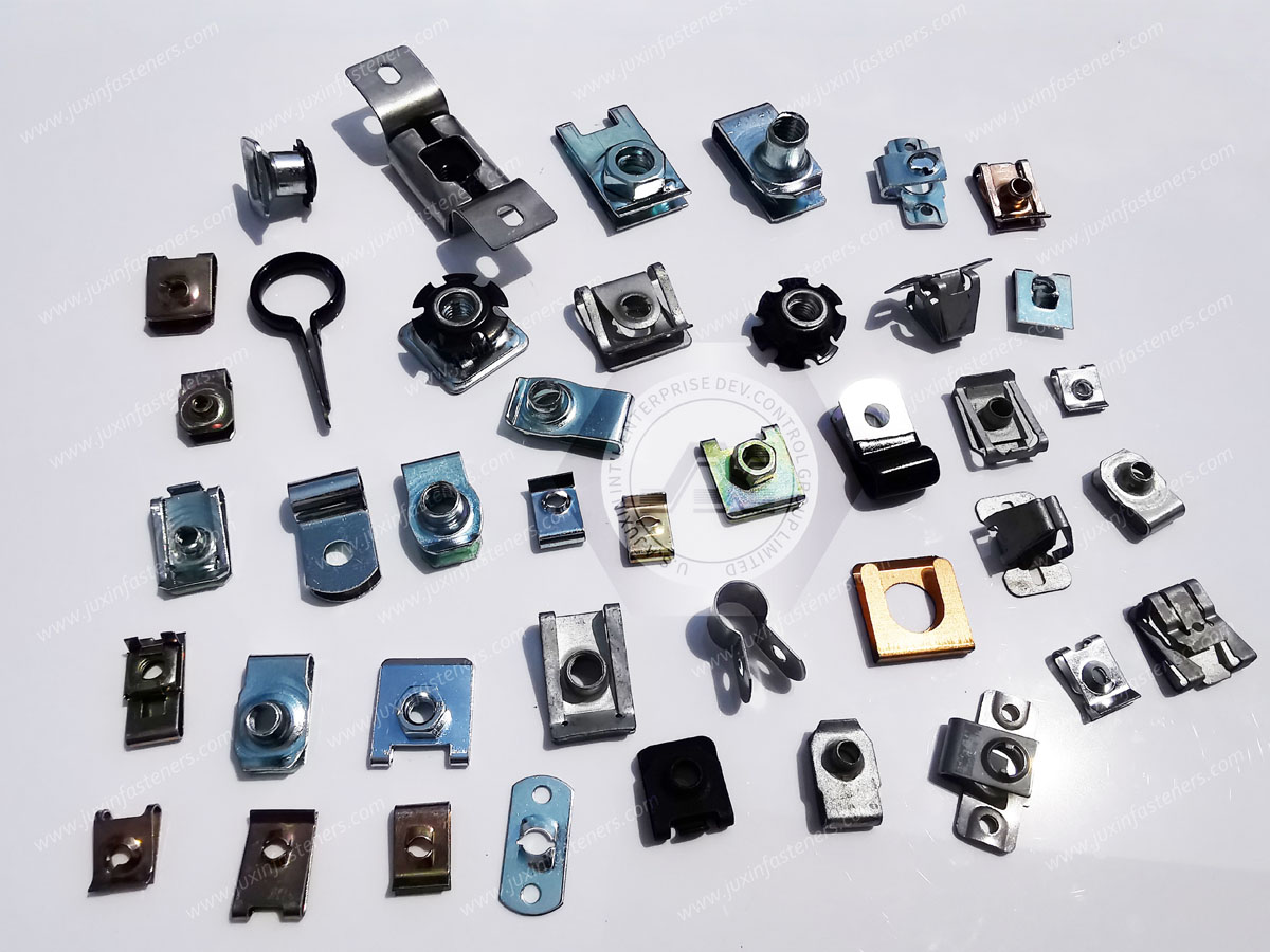
 MORE NEWS
Contact Us
Tel.:
+86 020 8621 0320
+86 020 3121 6067
E-mail:
Technical Support:
Navigation
SEND INQUIREY